Analysis of Uniaxial Alignment Behavior of Nonmagnetic Materials
under Static Magnetic Field with Sample Rotation
*Jun Akiyama
1, Hidefumi Asano
2, Kazuhiko Iwai
3and Shigeo Asai
41
Institute for Molecular Science, Okazaki 444-8585, Japan
2Department of Crystalline Materials Science, Nagoya University, Nagoya 464-8603, Japan
3Department of Materials, Physics and Energy Engineering, Nagoya University, Nagoya 464-8603, Japan 4Innovation Plaza Tokai Japan Science and Technology Agency, Nagoya 457-0063, Japan
A high magnetic field is a useful tool to control the crystal alignment of nonmagnetic materials such as metals, ceramics and polymers. However, the uniaxial alignment of hexagonal crystals with a magnetic susceptibility ofc< acannot be achieved under a static magnetic
field, because the c-axis could lie along any arbitrary direction in the plane perpendicular to the direction of the magnetic field. For the uniaxial alignment of these materials, the imposition of a rotating magnetic field during a slip casting process has been proposed.
In this study, both theoretical analysis and model experiment have been conducted for the elucidation of the crystal alignment phenomena under a rotating magnetic field and for the quantitative clarification of the optimum operating parameters such as magnetic field strength and viscosity of the medium surrounding the crystals. It has been found that the alignment time decreased with the magnetic field strength and/or with an increase in the viscosity of the surrounding medium. This relation is in contrary to the case of the crystal alignment under the static magnetic field. The result of the model experiment agrees well with that obtained by the theoretical analysis.
[doi:10.2320/matertrans.MRA2007326]
(Received December 21, 2007; Accepted February 13, 2008; Published March 19, 2008)
Keywords: electromagnetic processing of materials, crystal alignment, rotating magnetic field, magnetic anisotropy
1. Introduction
Crystal alignment control is one of the most important factors for improving the physical and chemical properties of polycrystalline materials with an anisotropic lattice struc-ture.1–4) The alignment control has been investigated using
various methods such as tape casting, pulse current pressure sintering and self-organization. However, it is difficult to obtain highly and uniformly aligned large-sized materials using such processes. On the other hand, the crystal align-ment of a diamagnetic material has been obtained exper-imentally under a static high magnetic field5–10) or the
simultaneous imposition of a static high magnetic field and sample rotation11–19) (rotating magnetic field) during a slip
casting process.
In this study, a theoretical analysis has been conducted and a model experiment has been performed for the elucidation of the crystal alignment phenomena under a rotating magnetic field and for the quantitative clarification of the optimum operating parameters such as the magnetic field strength and the viscosity of the medium surrounding the crystals.
2. Crystal Alignment under Magnetic Field
The principle of crystal alignment of a nonmagnetic material under a magnetic field is explained from the perspective of magnetization energy. When a nonmagnetic material is submerged in a magnetic field, the magnetization energyUis approximately given by
U¼ 1
20V?H
21
20VH
2cos2 ð1Þ
where0 is the magnetic permeability in vacuum, V is the volume of the material, ? is the magnetic susceptibility of the magnetic hard axis, is the difference in the magnetic susceptibility between the magnetic easy axis and the magnetic hard axis, H is the intensity of the imposed magnetic field andis the angle between the magnetic field direction and the magnetic easy axis.
The magnetic torque acting on the substance is given by the differentiation ofUwith respect toas follows:
T ¼ @U
@ ¼ 1
20VH
2sin 2 ð2Þ
Thus, the crystal under a magnetic field rotates in order to reduce the magnetization energy so as to be in a stable conformation.
In the case of imposing a magnetic field on a spherical crystal, which is surrounded by a viscous liquid medium, the alignment behaviour of the crystal is given by the following differential equation:
2 5r
5d 2
dt2 þ8r 3d
dt ¼T ð3Þ
where is the crystal density,ris the crystal radius and
is the viscosity of the surrounding medium. In the case that the particle size is small, the inertial term can be neglected. Then, the temporal variation of is derived from eq. (3) as follows:
tan¼tan0exp
t s
ð4Þ
S¼
6 0H2
ð5Þ
where 0 is the initial angle between the direction of the magnetic field and the magnetic easy axis of the crystal and S is the relaxation time for the crystal alignment *This Paper was Originally Published in Japanese in J. Japan Inst. Metals
71(2007) 108–112.
under the static magnetic field20) (hereafter, denotes the
‘alignment time’).
Let us consider the magnetic alignment of a crystal with a hexagonal lattice structure. The relationship between the imposed magnetic field and the magnetically stable direction of the hexagonal crystal is summarized in Fig. 1. For a magnetically anisotropic crystal with the relation a< c, the magnetization energy is the lowest when the c-axis of the crystal is parallel to the direction of the magnetic field (Uc<Ua). Therefore, the c-axis of the crystal aligns parallel to the direction of the magnetic field (Fig. 1(a)). On the other hand, the a-axis of the crystal aligns parallel to the direction of the magnetic field for crystals with the relation c< a (Ua<Uc). Therefore, with regard to the magnetic suscepti-bility of such a crystal, it is difficult to control the c-axis alignment under a static field (Fig. 1(b)).
3. Analysis of Crystal Alignment Behaviour under Rotating Field
It has been experimentally proven that the uniaxial alignment of a crystal with the magnetic susceptibility of
c< a can be obtained under a rotating magnetic field or by rotating the sample under a static magnetic field. We now define a system, as shown in Fig. 2, in order to analyze this phenomenon. A spherical crystal, whose magnetic anisotropy is c< a, is surrounded by a medium under a rotating magnetic fieldHð!Þ. The equation of the change is described by the following two simultaneous differential equations:
d
dt ¼ 1 2s
cos2ð’!tÞsin 2 ð6Þ
d’
dt ¼ 1 2s
sin 2ð’!tÞ ð7Þ
where!is the angular velocity of the rotating magnetic field and’is the angle between thec-axis and thexcomponent.
From eqs. (6) and (7), the alignment behaviours can be classified based onsas follows.
3.1 S! 1(HðtÞ !0and/or! 1)
ForS! 1, the right-hand term of eqs. (6) and (7) could be zero.
d
dt ¼0 ð8Þ
d’
dt ¼0 ð9Þ
Then,ðtÞand’ðtÞare given by the constant values for this limit. The boundary conditions are¼0and’¼’0(initial angles); the resulting solutions are then given as
¼0 ð10Þ
’¼’0 ð11Þ
It is understood that when the magnetic field is very small and/or the viscosity of the medium is very large, the magnetic field cannot supply sufficient torque to the crystal; subsequently, the anglesand’do not vary from their initial states.
3.2 S!0(HðtÞ ! 1and/or!0)
In this case, the left-hand term of eqs. (6) and (7) becomes zero.
cos2ð’!tÞsin 2¼0 ð12Þ
sin 2ð’!tÞ ¼0 ð13Þ Equation (13) gives the following solution:
’!t¼ð2nþ1Þ
2 ðn¼0;1;2; Þ ð14Þ
Hence, the angle ‘’!t’ is always maintained at=2rad. eq. (12) then becomes
0sin 2¼0 ð15Þ Therefore, Equation (12) holds for all values of. In such a case, it is impossible to achieve crystal alignment because there is no -component magnetic torque acting on the substance.
c-axis
c-axis
c-axis
B
B
χ
c
<
χ
a
χ
a
<
χ
c
a
b
Fig. 1 Alignment of hexagonal crystal under static high magnetic field. (a)a< c(b)c< a
ϕ
(
t
)
c
(
t
)
B
(
t
)
x
y
z
O
θ
(
t
)
ω
t
Crystal with magnetic anisotropy of
χc<χa
[image:2.595.47.291.70.296.2] [image:2.595.305.546.74.255.2]3.3 0< S<1
In the case that the crystal synchronously rotates with the magnetic field, the following relation holds true:
d’
dt ¼! ð16Þ
The integration of eq. (16) with respect totgives
’ðtÞ ¼!tþ ð17Þ Here, is the integration constant. Equation (7) can be rewritten in terms ofas
d
dt ¼ d
dtð’!tÞ ¼ 1 2s
sin 2!¼0 ð18Þ
is then given by
¼1
2arcsinð2s!Þ ¼ 1 2arcsin
12! 0H2
ð19Þ
Hence, the synchronous condition is given asS! <0:5; otherwise, it can be step-out. Substituting eq. (17) into eq. (6) gives the differential equation under this condition.
d dt ¼
1 2s
cos2sin 2 ð20Þ
It can be integrated with respect to t and this gives the temporal variation of the angle:
tan¼tan0exp
cos2
s
t
¼tan0exp
!t
tan
ð21Þ
R¼
tan ! ¼
2S
1 ffiffiffiffiffiffiffiffiffiffiffiffiffiffiffiffiffiffiffiffiffiffiffi14ðS!Þ2
p ð22Þ
Here, the boundary condition is¼0att¼0. The angle
decreases monotonically with time except under the initial condition 0¼=2. R denotes the alignment time for the crystal alignment under a rotating magnetic field in the synchronous mode. The optimum operating condition is
S!¼0:5, and in this case, the alignment time is twice of that under the static field (R¼2S). The differentiation ofR with respect toH,and!gives the following equations:
@R
@H ¼
Hð1þ ffiffiffiffiffiffiffiffiffiffiffiffiffiffiffiffiffiffiffiffiffiffiffi14ðS!Þ2 p
Þ
S!2
ffiffiffiffiffiffiffiffiffiffiffiffiffiffiffiffiffiffiffiffiffiffiffi
14ðS!Þ2
p >0 ð23Þ
@R
@ ¼
1þ ffiffiffiffiffiffiffiffiffiffiffiffiffiffiffiffiffiffiffiffiffiffiffi14ðS!Þ2 p
2S!2
ffiffiffiffiffiffiffiffiffiffiffiffiffiffiffiffiffiffiffiffiffiffiffi
14ðS!Þ2
p <0 ð24Þ
@R
@! ¼
2ðS!Þ2 ð1þ
ffiffiffiffiffiffiffiffiffiffiffiffiffiffiffiffiffiffiffiffiffiffiffi
14ðS!Þ2 p
Þ
S!3
ffiffiffiffiffiffiffiffiffiffiffiffiffiffiffiffiffiffiffiffiffiffiffi
14ðS!Þ2 p
¼ 2S
! ffiffiffiffiffiffiffiffiffiffiffiffiffiffiffiffiffiffiffiffiffiffiffi14ðS!Þ2
p 1þ
ffiffiffiffiffiffiffiffiffiffiffiffiffiffiffiffiffiffiffiffiffiffiffi
14ðS!Þ2 p
S!3
<0 ð25Þ
[image:3.595.308.546.74.257.2]The alignment timesS andR, which are calculated from eqs. (5) and (22) under various experimental conditions (¼1, 10 and 100 Pas,¼1:0105 and!¼0:3rad/ s), are plotted in Fig. 3. It is found thatRdecreases withH and/or an increase in!and. This relation is in contrary to the case of the crystal alignment under the static magnetic fieldS.
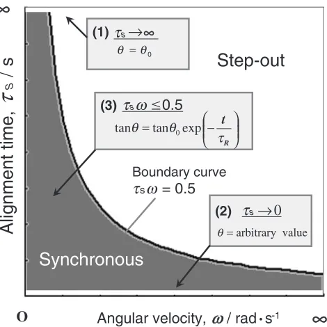
Figure 4 schematically shows the analyzed region in this time. The alignment behaviour of the crystal under the rotating field is clarified from this figure, except for that under the step-out mode.
4. Experimental
We have performed the following model experiment to verify the analytically derived relation amongR,Handof the medium. A schematic view of the experimental apparatus is shown in Fig. 5. An acrylic vessel (inside diameter: 20 mm, height: 40 mm) was filled with 4 mL of glycerine solution and placed on a rotating platform set at the centre of a bore in a superconducting magnet generating a horizontal static magnetic field. The viscosity of the glycerine solution was 5 Pas. The magnetic field and mould rotation were simultaneously imposed on a polymeric fibre
0 8 10 12
∆χ
∆χ = 1.0 × 10⁻⁵
ω= 0.3 rad • s-1 τR (η=1Pa • s)
τS(η=100Pa • s)
Magnetic flux density, µ0H / T
τR (η=10Pa • s)
τR (η=100Pa • s)
τS(η=10Pa • s)
τS(η=1Pa • s)
Alignment time,
τ
/ s
104
103
102
10
10-1
1
6 4 2
Fig. 3 Relation between alignment timeand magnetic flux density,0H.
Alignment time,
τ
S
/
s
Angular velocity,
ω
/ rad
•s
-1∞
O
Boundary curve
τ
sω
= 0.5
0
θ θ =
(1)
τ
s∞
τ
s0.5
∞
(3)
− =
R t τ θ θ
= arbitrary value θ
exp tan
tan 0
(2)
τ
s↑
↑
0
Synchronous
Step-out
ω
[image:3.595.312.547.306.541.2] [image:3.595.58.293.559.699.2](d¼0:235mm,l¼8mm) after it was placed in the vessel. In this case, the added mass effect due to the non-spherical object shape in eq. (3) is negligible. The alignment behaviour of the fibre was recorded by a high-speed video camera to evaluate the anglesand.
The magnetic susceptibility of the fibre was previously measured by a vibrating sample magnetometer (VSM). The resulting data are presented in Table 1. The magnetic easy axis is in the radial direction, and the value of the magnetic anisotropyis2:7106[-]. The experimental conditions and the theoretical alignment time obtained using eqs. (5) and (22) are listed in Table 2.
5. Results and Discussions
Figure 6 shows the time variation of the orientation of the fibre. The upper and lower halves of each image show the top view through the reflecting prism and the side view of the sample, respectively.
In the case of imposing a magnetic field of 4 T (Fig. 6(a)), the long axis of the fibre becomes almost parallel to the axis of the rotating magnetic field within 10 s. The alignment time is prolonged when the strength of the magnetic field is increased (Fig. 6(b)), and in the case of a magnetic field of 6 T, the alignment is not achieved even after 20 s of the imposition of the magnetic field and rotation (Fig. 6(c)).
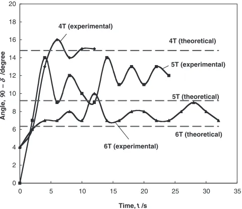
The time variation of(¼’!t), obtained from Fig. 6, is illustrated in Fig. 7. The alignment in the first four seconds
of the imposition of the magnetic field is in the step-out mode because of the change in. After 4 s,becomes constant and the alignment behaviour changes from the step-out mode to the synchronous mode.
Figure 8 illustrates the time dependence of . The solid lines denote the calculated values, and the dotted lines denote the actual measurement values. R decreases with the B
Superconducting Magnet Turn Table Video
Camera
Light Source PC
Reflecting Prism Recorder
Vessel
Fig. 5 Schematic view of the experimental apparatus.
Table 1 Magnetic Susceptibility.
Direction Susceptibility[] Anisotropy[] c-axis 1:08105
2:7106
[image:4.595.51.289.73.223.2]a-axis 8:11106
Table 2 Experimental condition.
Sample
Magnetic Flux Density
B/T
Rotating velocity
!/rads1
Viscosity
/Pas
Relaxation time
S/s
Relaxation time
R/s
a 4 0.3 5 0.85 11.7
b 5 0.3 5 0.56 19.3
c 6 0.3 5 0.39 28.3
Upper view
(Through the reflecting prism)
Side view
(a) µ0H=4T
0s 5s 10s (b) µ0H=5T
0s 10s 20s
(c) µ0H=6T
0s 10s 20s
Fiber
Fig. 6 Alignment of polymeric fibers under high magnetic field and mold rotation. (a)0H¼4T, (b)0H¼5T, (c)0H¼6T
0 2 4 6 8 10 12 14 16 18 20
0 5 10 15 20 25 30 35
Angle,
9090
−
δ
/degree
Time, t /s
4T (theoretical)
5T (theoretical)
6T (theoretical) 4T (experimental)
5T (experimental)
6T (experimental)
[image:4.595.311.542.76.398.2] [image:4.595.45.291.349.435.2] [image:4.595.308.548.458.665.2]magnetic flux density, and these experimental results quantitatively agree with the calculated ones.
6. Conclusion
In this study, a theoretical analysis has been conducted and a model experiment has been performed for elucidating the crystal alignment phenomena under a rotating magnetic field. It has been analytically found that the alignment time decreases with the magnetic field strength and/or with an increase in the viscosity of the surrounding medium. This relation is in contrary to the case of the crystal alignment under a static magnetic field. The result of the model experiment agrees well with that obtained by the theoretical analysis.
Acknowledgement
This research was partially supported by the Ministry of Education, Culture, Sports, Science and Technology, Grant-in-Aid for Exploratory Research (No. 16656209), ‘‘Creation of Nature-Guided Materials Processing’’ of the 21st Century COE Program, Research support program of SEKISUI CHEMICAL Company and JSPS Asian Core Program ‘‘Construction of the World Center on Electromagnetic Processing of Materials’’.
REFERENCES
1) S. Li, K. Sassa and S. Asai: J. Am. Ceram. Soc.87(2004) 1384–1387. 2) T. Kuribayashi, M. G. Sung, K. Sassa and S. Asai: CAMP-ISIJ18
(2005) 801–802.
3) J. Akiyama, M. Hashimoto, H. Takadama, F. Nagata, Y. Yokogawa, K. Sassa, K. Iwai and S. Asai: Key. Eng. Mater.309–311(2005) 53–56.
4) J. Akiyama, M. Hashimoto, Hiroaki Takadama, Fukue Nagata, Yoshiyuki Yokogawa, Kensuke Sassa, Kazuhiko Iwai and Shigeo Asai: Mater. Trans.46(2005) 2514–2517.
5) H. Morikawa, K. Sassa and S. Asai: Mater. Trans. JIM39(1998) 814– 818.
6) T. Suzuki, Y. Sakka and K. Kitazawa: J. Cera. Soc. JP109(2001) 886– 890.
7) T. S. Suzuki and Y. Sakka: Jpn. J. Appl. Phys.41(2002) 1272–1274. 8) M. Tahashi, M. Ishihara, K. Sassa and S. Asai: Mater. Trans. JIM44
(2003) 285–289.
9) K. Inoue, K. Sassa, Y. Yokogawa, Y. Sakka, M. Okido and S. Asai: Mater. Trans.44(2003) 1133–1137.
10) Y. Sakka and S. Suzuki: J. Ceramic Soc Japan113(2005) 26–36. 11) Shinger LS and Lewis RT: 11th Biennial Conference on Carbon at
Gatlinburg, Extended Abstract CG-27 (1973) 207–208.
12) S. Li, K. Sassa, K. Iwai and S. Asai: Mater. Trans.45(2004) 3124– 3129.
13) T. Kimura, M. Yoshino, T. Yamane, M. Yamato, and M. Tobita: Langmuir20(2004) 5669–5672.
14) J. Akiyama, M. Hashimoto, H. Takadama, F. Nagata, Y. Yokogawa, K. Sassa, K. Iwai and S. Asai: Mater. Trans.46(2005) 203–206. 15) T. Kimura and M. Yoshino: Langmuir21(2005) 4805–4808. 16) K. Iwai, J. Akiyama, M. G. Sung, I. Furuhashi and S. Asai: Sci.
Technol. Adv. Mater.7(2006) 365–368. 17) T. Kimura: Polymer Journal35(2003) 823–843.
18) C. Wu, S. Li, K. Sassa, Y. Chino, K. Hattori and S. Asai: Mater. Trans.
46(2005) 1311–1317.
19) T. Sugiyama, K. Sassa and S. Asai: Proceedings of 6th Meeting of symposium on New Magneto-Science pp. 5–10.
20) T. Kimura, M. Yamato, W. Koshimizu, M. Koike, and T. Kawai: Langmuir16(2000) 858–861.
Appendix
B: Magnetic flux density (T)
d: Diameter (m)
H: Magnetic field strength (Am1)
l: Length of fiber (m)
r: Radius (m)
t: Time (s)
T: Magnetic torque (Nm)
U: Magnetization energy (J)
V: Volume (m3)
x;y;z: Cartesian coordinate (-)
: Angle (rad)
: Magnetic anisotropyjacj(-)
: Viscosity (kgm1s1)
: Angle (rad)
0: Magnetic permeability in vacuum (Hm1)
: Density (kgm3)
R; S: Alignment time (s)
’: Angle (rad)
: Magnetic susceptibility (-)
a: Magnetic susceptibility of a axis (-)
c: Magnetic susceptibility of c axis (-)
?: Magnetic susceptibility of hard axis (-)
!: angular velocity (rads1)
-10 0 10 20 30 40 50 60 70 80
0 5 10 15 20 25 30 35
Angle,
θ
/degree
Time, t /s 6T 6T
4T 4T
5T 5T
:Calculated