induced defect clusters under these conditions. [doi:10.2320/matertrans.MD201311]
(Received September 10, 2013; Accepted December 20, 2013; Published February 15, 2014)
Keywords: nickel-based alloys, ion irradiation effects, microstructure, TEM in situ ion irradiation, defect evolution, molten salt nuclear reactors
1. Introduction
The neutron fluence and spectrum in any reactor system poses a major challenge to a material’s structural integrity and radiation resistance. Specifically for candidate materials targeted for use in Generation IV molten salt reactors (MSR), the combination of high-energy neutrons, elevated temperatures and salts that enhance corrosion introduce significant complexities when selecting appropriate structural materials required for core, circuitry and fuel reprocessing components.1,2)
From past research, nickel-based (Ni) alloys have proven versatile as high temperature, high strength materials in MSR systems due to their excellent heat and corrosion resistant properties compared to austenitic and ferritic-martensitic steels.36) Of these, nickel-based super alloys, including several families of Inconel, Hastelloy and Incoloy, have been found most promising due to their exceptional compatibility with molten fluoride salts at temperatures above 973 K. Considerable research was undertaken in the latter half of the last century on the behavior of NiMoCr alloys for use in molten salt reactors and the body of work has been reviewed in recent years.79) Typical Gen IV Molten Salt Reactor designs operate at higher temperatures and with much extended operational lives than the prototype reactors built in the last century. For these reactors to become a reality we need to identify, design and produce materials that can withstand the extreme conditions of radiation, temperature, chemical environment and stress inherent in advanced nuclear systems. This requires us first to understand and develop predictive models of their failure mechanisms so that we can develop design codes and defect-assessment criteria that ensure structural integrity.10) This requires an under-standing of the mechanisms devoted to such properties, as the ability of multi-scale models to describe radiation damage is improving.1113)
However, only a relatively small number of studies have been undertaken in regards to the irradiation behavior of Ni-based alloys at high-dose, high-temperature levels and even less for alloys containing molybdenum and chromium solutes that are believed to provide oxidation protection along with high temperature creep and hardening resistance during irradiation.7)Under such detrimental conditions, these factors are important in determining a material’s long-term efficacy. Druzhkovet al.examined the structure and phase states in NiMoCr (1.3Mo32Cr, mass%) alloys irradiated by 5 MeV electrons at 573 K and found defect migration initiates a process of ordering and phase separation depending on the initial alloys’microstructure and chromium content.14)They also noted that higher chromium concentrations impeded the accumulation of vacancy defects after a dose of 1.5© 10¹4dpa at 473 K. Similar observations of irradiation-induced order transformations were also found by Wanderka
et al. on a Hastelloy alloy (7.3Mo7.2Cr, mass%) after 10 MeV electron irradiation at 923 K due to the presence of L12-type precipitates.15)Recently, Jin et al.investigated the radiation damage effects in nickel alloy C-276 (15.5Mo 16Cr, mass%) using 120 keV Ar+ ions to peak dose levels of 6 and 10 dpa at 573 and 773 K.16) Here, results showed a decrease in dislocation loop density with an increase in irradiation dose and temperature, while irradiation hardening was found the greatest after a dose of 6 dpa at 573 K.
As the process of irradiation-induced microstructural evolution changes in response to environmental variants (i.e., dose rate, temperature, salt, material composition, lattice structure), it is therefore essential to understand the mechanisms that drive such change in order to improve a materials performance under in-service conditions. Thus, a critical part of this effort is to evaluate damage evolution as it develops under irradiation. Transmission electron microscopy (TEM) with in situ ion irradiation capability offers one unique way to observe this phenomenon as it allows variables such as ion type, irradiation dose and temperature to be controlled judiciously in real-time.1719)
In this study, the fundamental damage processes that affect the microstructural stability of a NiMoCrFe alloy under heavy-ion irradiation are investigatedin situas a function of dose rate and temperature (723 and 973 K). An emphasis is placed on the density and size distribution of irradiation-induced defect clusters that accelerate the degradation and bulk diffusion processes in this alloy due to the formation of defects by primary damage events that occur under fast-neutron irradiation conditions.
2. Experimental Procedure
The NiMoCrFe alloy (now referred to here Ni-MOCrFe1) was obtained as a bar stock from the Shanghai Institute of Applied Physics in Shanghai, China. The chemical composition as determined using the LECO combustion method and inductively coupled plasma atomic emission spectroscopy (ICP-AES, Varian Liberty Series II) is given in Table 1. The concentrations of sulfur, phosphorus, niobium, titanium and cobalt were less than 0.02 mass%.
The microstructure before irradiation was characterized using a Zeiss Ultra Plus scanning electron microscope (SEM) with an accelerating voltage of 20 keV and a JEOL 2200F transmission electron microscope (TEM) in scanning mode (STEM) operated at 200 keV. Specimens prepared for SEM analysis were first cut into 5©5©1 mm3 bars with the cross-sections polished along the longitudinal direction using standard metallographic techniques.20) Successive grades of diamond paste (to 1 µm) and colloidal silica (to 0.05 µm) were used for thefinal polish. Thin foil TEM samples were prepared by jet polishing pre-punched 3 mm disks with an electrolyte solution of 30% nitric acid (HNO3) and 70%
methanol (CH3OH) at room temperature. Thefinal thickness of the samples was approximately 100 nm.
Heavy ion irradiation experiments were performed in situ
at the IVEM-Tandem facility at Argonne National Labora-tory. The facility consists of a Hitachi H-9000NAR TEM interfaced to a 2 MeV NEC Tandem Van de Graff accelerator and a 650 keV NEC ion implanter.21) For this investigation, the microscope was operated at 200 keV, which is below the threshold for knock-on damage. The jet polished TEM samples were irradiated with 1 MeV Kr2+ ions using a counting rate of 50 ion counts s¹1 and a flux of 6.25© 1011ions cm¹2s¹1. The corresponding doses in displace-ments per atom (dpa) were calculated by SRIM-2013 with full damage cascades and atomic displacement energies of 50 keV for each species. All samples were irradiated to 3.3©1014ions/cm2 (1 dpa), 9.4©1014ions/cm2 (3 dpa) and 1.54©1015ions/cm2 (5 dpa) at 723 and 973 K in a Gatan double-tilt heating holder, with the temperature regulated within «274 K by a thermocouple attached to the holder. Data was recorded at regular intervals using a Gatan 622 video camera and stopped frequently to carry out microscopic analysis.21)The single diffraction condition used in this study, however, was not sufficient enough to fully characterize the type and nature of defects observed, though will be addressed in a subsequent paper.
3. Results and Discussions
3.1 Microstructure
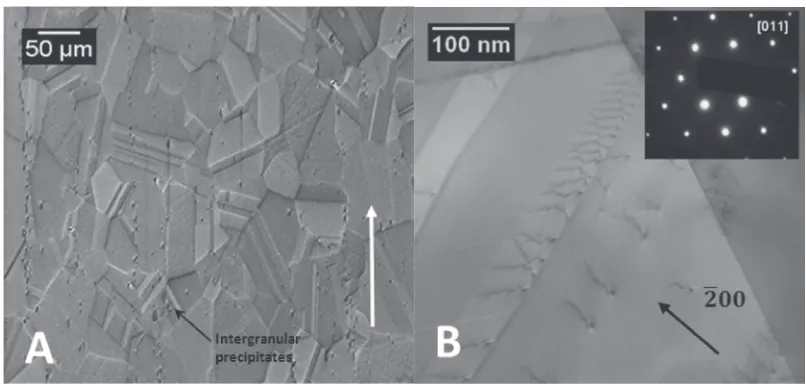
[image:2.595.96.499.68.262.2]Figure 1(a) presents a secondary electron (SE) SEM micrograph of the as-received alloy which reveals a micro-structure comprised of polycrystalline equiaxed grains with high-density annealing twins, characteristic of low-stacking-fault energy Ni-based alloys with high amounts of solute.22) The average grain diameter wasµ40 µm, with twin structures having typical widths of a few tens of microns. Large intergranular precipitates (15 µm), identified as complex © -carbides, were also found interspersed both randomly and as stringers along the axial direction.
Table 1 Chemical composition of the NiMoCrFe alloy (mass%).
Ni Mo Cr Fe Mn Si Al C
bal. 16.0 6.40 3.62 0.58 0.43 0.06 0.05
[image:2.595.44.293.338.366.2]Figure 1(b) shows a representative brightfield (BF) STEM image taken under ag¼ ½200two-beam condition, close to the [011] direction, wheregis the diffraction vector indicated by an arrow in thefigure. Under these conditions, sub-micron twins were observed in addition to a linear array of planar dislocations. Such dislocations, predominantly of mixed character, indicate that small short-range order (SRO) regions exist, which are strong enough to inhibit cross-slip such that dislocations are confined to a single slip plane. This is evidenced by the hindrance of dislocation propagation between neighboring grain boundaries where dislocation absorption and emission are absent in this case. Subse-quently, the evolution of the microstructure from heating and accumulation of defects was monitored using this zone axis, i.e.,h110i.
3.2 Annealing
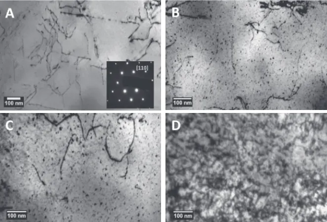
Followingin situheating to temperatures of 723 and 973 K significant differences in phase morphology were observed, altering the dislocation structure and matrix of each sample. Figure 2(a) shows a BF TEM image of the alloy at 723 K, illustrating the transformation from an initial periodic dislocation configuration to a loose network of tangled dislocations and kinks that nucleate as a consequence of image forces activating slip propagation and dislocation glide between {111} slip planes. Although recovery alleviates the stored strain energy from plastic deformation, the driving force for static recrystallization at this temperature is clearly insufficient. By 973 K, the microstructure develops beyond the formation of tangles and evolves as a result of sub-grain coalescence through grain boundary migration and growth (Fig. 3(a)). Thermally activated dislocation annihilation also manifests here, as indicated by the marked decrease in dislocation density when compared to annealing at 723 K. In addition to dislocation extinction heterogeneous formation of intergranular M23C6-type secondary carbides (1050 nm) also occurred, derived from either dislocation-enhanced
diffusion or dissolution from primary particles present in the£matrix.23)Suchfindings are in agreement with previous studies on Ni-based alloys annealed to 973 K by Tytko
et al.24)
3.3 Irradiation
Upon irradiation with 1 MeV Kr ions, as expected, the temperature had a significant influence on the microstructural evolution with increasing fluence. Figures 2 and 3 show a sequence of BF TEM images taken during irradiation at 723 and 973 K, respectively. In both cases, a marked increase in the volume fraction of visible defects is observed, albeit with differences in the nature and extent of defects produced in each case. Where the contrast is sensitive to local areas of strain, these features appear as random black dot defects arising from the collapse of local vacancy-rich regions produced heterogeneously at the core of displacement cascades during irradiation.25) As observed in previous reports,26,27) resolvable point defects of this nature were identified as vacancy clusters (< 2 nm) and interstitial-type dislocation loops (>5 nm) with Burgers vector a=2h110iin f111gh011islip systems in Ni-alloys.
With increasing dose at 723 K, such defects were found to proliferate around in-grown dislocation segments and by 5 dpa, the damage structure evolves from a random distribution of point defect clusters to a dense network of tangled dislocations by the growth and unfaulting of dislocation loops during cascade collapse [Figs. 2(b)2(d)]. Dislocations of this nature evidence the dominant long-range elastic interactions between them; though appear randomly distributed due to the inherently low stacking fault energy of the matrix.
After successive annealing to 973 K, thermal recovery of the network is observed at 1 dpa damage, during which vacancies anneal out, precipitates shrink and dislocations rearrange by thermal activation (glide and climb), thereby reducing the overall internal stresses induced by heating
[image:3.595.133.464.71.296.2](Fig. 3(b)). The process of recrystallization is also apparent here as adjoining subgrains merge into the same orientation by strain-induced boundary migration and diffusion. By 3 dpa, continued cascade damage cause the eventual dissolution of precipitates (³ 40 nm) that, in turn, lead to the unpinning of interfacial dislocations created from misfit stresses (Fig. 3(c)). From 3 to 5 dpa, damage structures show only a small dependence on irradiation, with both consisting of point defect clusters and bowed dislocation segments [Figs. 3(d)3(c)]. Dislocation loops and half-loops were also observed in this case, with the growth of loops attributed to interstitial-type loops and the shrinkage to vacancy loops as interstitial defects have larger strain fields compared to vacancies.28,29)
3.4 Defect density and cluster fraction
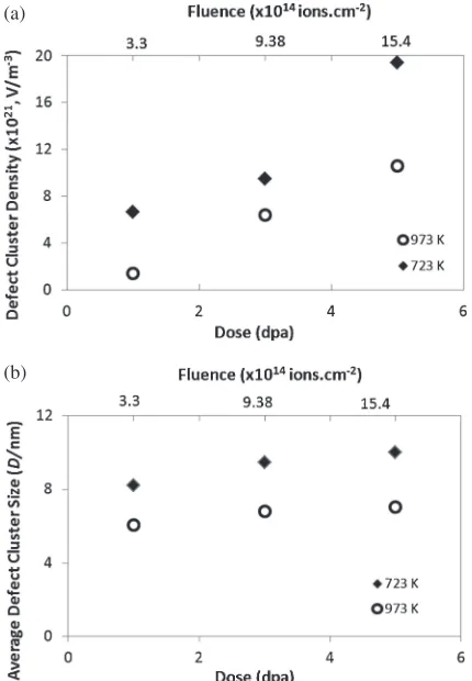
Since defect nucleation and loss fundamentally govern the net residual damage in irradiated materials, the effect of irradiation temperature can therefore provide insight into the two competing processes. Plots of the defect size and density against dose at 723 and 923 K are given in Fig. 4. Only defect clusters above 2 nm were included in the experimental data, as defects below this value were unresolvable under our experimental conditions.
For both temperatures, the resulting defect size was seen to increase with increasing dose as the probability of defect formation and growth expanded through the rise in local vacancy and interstitial concentrations (Fig. 4(a)). At 723 K, sizes were found from 810 nm, while the maximum range at 973 K varied only by 15%from 67 nm between 1 to 5 dpa. A linear increase in the defect cluster density was also observed to occur by cascade overlap, where distances between successive displacement collisions decreased rela-tive to the increase in collision cross-sections (Fig. 4(b)).30,31) Though defect density and size were found to increase with increasing dose, the result was more pronounced at 723 K compared to 973 K. This can be attributed to the differences in damage accumulation rate, where the number density of
defects was found roughly 45%higher at 723 K for all dose levels. From molecular dynamics (MD) studies, the greater defect cluster production efficiency at this temperature maybe due to thermal spike effects associated with differences in electronphonon coupling during Kr ion bombardment.32) That the microstructure evolves into a tangled network of dislocations by 5 dpa at 723 K imply that nucleation and
(a)
(b)
Fig. 4 Dose dependence of (a) defect cluster size and (b) defect cluster density as a function of irradiation temperature.
[image:4.595.132.461.70.294.2] [image:4.595.320.535.336.646.2]interaction between interstitial-type defects are quite prom-inent at this temperature, which reflects the balance between defect formation and coalescence by saturation. At 973 K however, clusters often exhibit positionalfluctuations during their formation as they move discontinuously within the matrix by random jumps.33)
While a marked increase in defect density and size is apparent as irradiation progresses at 973 K, quantification of the defect cluster yield may be lower due to the long-range migration capability of mobile defects, such that vacancy concentrations in cascades decrease below the threshold for cluster nucleation. Additional mechanisms for the decrease in defect cluster yield at higher temperatures include the rapid diffusion and annihilation of oppositely signed defects, loss by glide to the foil surface and interactions with pre-existing dislocation features due to their efficiency as sinks.33,34)
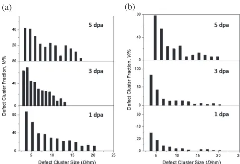
The corresponding defect cluster distributions are shown in Fig. 5. Interestingly, the cluster fraction seems relatively insensitive to temperature; however, it appears that an increase in the number of larger defects and a reduction in the number of smaller defects manifest at higher doses, and it is envisaged that the latter significantly contributes to the growth of defect size. Though the types of defects are uncertain at this stage, many large defect clusters found in Ni-based alloys at high irradiation temperatures are generally imperfect stacking fault tetrahedra (SFT) and large interstitial loops.35,36)
No voids or cavities were observed under the experimental conditions reported here. Previous work on void formation in Ni-based alloys with large impurity concentrations suggest that the incubation doses for swelling are in excess of 100 dpa at temperatures above 773 K, owing to the lower stacking fault energies of these materials compared to pure Ni where void formation was observed between 2270 dpa at temper-atures below 773 K.37)
4. Conclusion
The effect of Kr ion irradiation on the microstructural evolution of a NiMoCrFe alloy was investigated in situ
for doses up to 5 dpa at 723 and 973 K. It was found that damage formation was a result of cascade overlap, resulting
This project is supported by the Commonwealth of Australia under the AustraliaChina Science and Research Fund. The research conducted at the IVEM-Tandem Facility is supported as a User Facility by the U.S DOE, Basic Energy Sciences, under contract W-31-10-ENG-38. We are grateful to Peter Baldo and Edward Ryan of Argonne National Lab for help in performing irradiations as well as Dr. Pranesh Dayal and Dr. Ondrej Muransky for assistance with SEM work. We thank Honjie Xu of the Shanghai Institute of Applied Physics for the supply of the NiMoCrFe alloy.
REFERENCES
1) P. Yvon and F. Carre:J. Nucl. Mater.385(2009) 217222.
2) L. Mathieu, D. Heuer, R. Brissot, C. Le Brun, E. Liatard, J. M. Loiseaux, O. Meplan, E. Merle-Lucotte, A. Nuttin, J. Wilson, C. Garzenne, D. Lecarpentier and E. Walle:Prog. Nucl. Energy48(2006) 664679.
3) P. Kritzer, N. Boukis and E. Dinjus:Corrosion56(2000) 10931104.
4) L. K. Mansur, A. F. Rowcliffe, R. K. Nanstad, S. J. Zinkel, W. R. Corwin and R. E. Stoller:J. Nucl. Mater.329333(2004) 166172.
5) L. Heikinheimo, P. Aaltonen and A. Toivonen:Energy Mater. Mater. Sci. Eng. Energy Syst.2(2007) 7277.
6) P. Shi, A. Engstrom and B. Sundman:J. Environ. Sci.23(2011) S1S7.
7) C. Le Brun:J. Nucl. Mater.360(2007) 15.
8) A. S. Bakai: NATO Science for Peace and Security Series B, (Physics and Biophysics, Netherlands, 2008) pp. 537557.
9) S. Delpech, C. Cabet, C. Slim and G. S. Picard:Mater. Today13(2010) 3441.
10) R. W. Grimes, R. M. Konings and L. Edwards:Nat. Mater.7(2008) 683685.
11) A. Arsenlis, B. D. Wirth and M. Rhee:Philos. Mag.84(2004) 3617 3635.
12) C. Deo, C. Tome, R. Lebensohn and S. Maloy:J. Nucl. Mater.377 (2008) 136140.
13) A. Boyne, C. Shen, R. Najafabadi and Y. Wang:J. Nucl. Mater.438 (2013) 209217.
14) A. P. Druzhkov, V. P. Kolotushkin, V. L. Arbuzov, S. E. Danilov and D. A. Perminov:Phys. Met. Met.101(2006) 369378.
15) N. Wanderka, A. Bakai, C. Abromeit, D. Isheim and D. N. Seidman:
Ultramicroscopy107(2007) 786790.
16) S. Jin, X. He, T. Li, S. Ma, R. Tang and L. Guo:Mater. Charact.72 (2012) 814.
17) C. W. Allen and E. A. Ryan:Microsc. Res. Tech.42(1998) 255259.
18) R. C. Birtcher, M. A. Kirk, K. Furuya, G. Lumpkin and M. O. Ruault:
J. Mater. Res.20(2005) 16541683.
19) J. A. Hinks:Nucl. Instrum. Methods B267(2009) 36523662.
20) J. R. Davis (ed.):Nickel, Cobalt, and Their Alloys, (ASM Specialty Handbook, ASM International, Ohio, 2000) pp. 6891.
[image:5.595.47.288.69.234.2]22) S. Mahajan:Scr. Mater.68(2013) 9599.
23) C. Y. Cui, Y. F. Gu, D. H. Ping and H. Harada:Metall. Mater. Trans. A 40(2009) 282291.
24) D. Tytko, P. Choi, J. Klower, A. Kostka, G. Inden and D. Raabe:Acta Mater.60(2012) 17311740.
25) D. Xu, B. D. Wirth, M. Li and M. A. Kirk:Appl. Phys. Lett.101(2012) 101905.
26) R. M. Boothby:Comprehensive Nuclear Materials, (2012) pp. 123 150.
27) T. M. Robinson and M. L. Jenkins:Philos. Mag.43(1981) 9991015.
28) P. R. Okamoto and H. Wiedersich:J. Nucl. Mater.53(1974) 336345.
29) L. E. Rehn, P. R. Okamoto and R. S. Averback:Phys. Rev. B30(1984) 30733080.
30) A. Tenenbaum and N. V. Doan:Philos. Mag.35(1977) 379403.
31) V. Naundorf, M. P. Macht and H. Wollenberger:J. Nucl. Mater.186
(1992) 227236.
32) M. Beranger, P. Thevenard, R. Brenier, B. Canut and S. M. M. Ramos:
Phys. Rev. B53(1996) 1477314781.
33) J. S. Vetrano, I. M. Robertson, R. S. Averback and M. A. Kirk: Effects of Radiation on Materials, 15th International Symposium, ASTM STP 1125, Philadelphia, (1992) pp. 375384.
34) S. L. King, M. L. Jenkins, M. A. Kirk and C. A. English: Effects of Radiation on Materials, 15th International Symposium, ASTM STP 1125, Philadelphia, (1992) pp. 448462.
35) K. Yamakawa and Y. Shimomura:J. Nucl. Mater.264(1999) 319326.
36) Y. N. Osetsky, D. Rodney and D. J. Bacon:Philos. Mag.86(2006) 22952313.