Effect of Sintering Pro
fi
le and Composition of Ni
/
Al
2O
3Functional Gradient
Materials Coating Layers via Pulsed DC Electrophoretic Deposition
Hyungsub Kim, Seungkyu Yang and Caroline Sunyong Lee
+Department of Materials Engineering, Hanyang University, Gyeonggi-do, 426-791, Korea
Ni/Al2O3functional gradient material (FGM) coating layers with its thickness of 2025 µm were fabricated by pulsed direct current (DC)
electrophoretic deposition (EPD). The coarsening effect of Ni was studied to control sintering profile with an intermediate step of 1000°C for 3 h. Controlling the sintering conditions through an intermediate step and varying the number of layers played important roles in reducing cracks on the coating surface. The samples were characterized using X-ray diffraction (XRD), back scattered electron microscopy (BSE) and electron probe micro analyzer (EPMA). From these analyses, the effects of sintering step on microstructures of FGM coating layers were studied systematically to minimize crack problems within Ni-rich region by controlling its composition and form gradient through coarsening of Ni particles caused by intermediate step during sintering process. The high hardness was found for two- and three-layered samples by introducing intermediate step during sintering. Hence, pulsed DC EPD method was successfully employed to fabricate crack-free FGM with desirable microstructures. [doi:10.2320/matertrans.M2013347]
(Received September 9, 2013; Accepted December 9, 2013; Published January 31, 2014)
Keywords: electrophoretic deposition, pulse, nickel, Al2O3, functional gradient material, sintering profile, composite, coating
1. Introduction
Functionally graded material (FGM) is a joining method that creates a continuous change in composition from one side of the bond to the other, with an accompanying gradient in thermal expansion properties while minimizing the residual stress by providing a gradual transition. Numerous studies have described metalceramic FGM that combine the high temperature resistance of ceramics with the toughness of metals.1,2) These materials exhibit different interesting properties at different regions and can be used in areas of research and development that require advanced structures, such as advanced engines, turbine blades, and thermal barrier coatings. Due to various useful properties and important applications, FGM have been studied over last few years.35) Ni is known for its structural and thermal stability at high temperature (up to 1445°C). Al2O3 has many desirable properties among ceramic materials, such as high thermal and corrosion resistance, high hardness, and a relatively large coefficient of thermal expansion, which makes them compatible with metals. Various fabrication processes have been reported for FGM, such as plasma spraying, centrifugal casting, powder metallurgy, physical vapor deposition (PVD), chemical vapor deposition (CVD), and electro-phoretic deposition (EPD).1,6,7) However, since powder metallurgy using cold pressing or cold isostatic pressing has some limitations in shape and size that can be fabricated, EPD was employed to coat the FGM layers. EPD is a process where colloidal particles suspended in a liquid medium, such as water and organic solvent, migrate and are deposited onto an electrode under the influence of an electricalfield (voltage or current). It has relatively fast coating speeds, and simple system compared to aforementioned methods. Further, the complex object can be coated easily and uniformly by controlling deposition time, voltage, and current with desirable thickness.6,810) However, crack problem during drying and sintering processes is an inherent problem for
fabrication process related to ceramics in general. To overcome this problem, various methods are used to prevent crack such as adding polymeric binders, reinforcement with fiber materials, controlling its particle size, employing a specific drying process and etc.1116)
Pulsed DC EPD is an effective method of controlling particle movement by varying the duty cycle, pulse width, and on/off time of the applied voltage/current. This method controls the electrolysis of the solvent and provides a uniform coating after a very short processing time because of the mass transport of particles from the bulk suspension towards the surface electrode, which is likely to continue even when the voltage/current is off due to their inertia of mobility. Studies on improving the coating conditions while controlling incorporated bubbles using pulsed DC EPD, have been conducted.1719)Generally, a pulsed DC EPD method instead of conventional DC EPD can yield deposits or coatings with improved surface appearance and properties, such as smoothness and refined surface of greens.20) Moreover, studies done by S. C. Wang and B. C. Huang21) reported that the morphology of thefilms coated by pulsed DC EPD exhibited almost crack-free surface after heat treatment and the uniformity of the thickness was also improved by the pulsed DC EPD deposition. Although organic solvent is used with pulsed DC EPD in this research, coating thickness can be controlled to minimum thickness by applying pulse in EPD compared to the layers deposited using DC EPD. Therefore, deposition by changing the suspension in each composition to fabricate FGM coating layers was inves-tigated using pulsed DC EPD. Moreover, the effect of an intermediate step during the sintering process and controlling the number of layers to obtain uniform and thin Ni/Al2O3 FGM layers were investigated via pulsed DC EPD.
2. Experimental Procedure
Al2O3 powders (Taimei Chem, TM-DAR, average size: 0.18 µm) and NiO powders (TASCO, AM30, average size: 1 2 µm) were separately suspended with varying compositions +Corresponding author, E-mail: sunyonglee@hanyang.ac.kr
in ethanol. A suspension concentration of 5 vol% was used. Because Ni has a higher density than that of Al2O3sediments in suspension, NiO powders were used and then reduced during sintering to obtain uniform dispersion. The pH values of the Al2O3100%and NiO 100%suspensions were adjusted by acetic acid (CH3COOHDaejungchem, Korea). Zeta potential and electrophoretic mobility were measured via a zeta potential measurement (Malvern, Zetasizer Nano, UK). Each suspension of mixed composition was ultrasonicated for 5 min to disperse the particles uniformly in the solution, and then stirred for 24 h at 350 rpm.
Pulsed DC EPD was conducted at 75 V using the system source meter (Keithley, Model 2611A USA) with 50%duty cycle with its voltage on for 10 ms and voltage off for 10 ms. Moreover, deposition time for each composition was 5 s except 100% Al2O3 layer where 7.5 s was used to obtain uniform coating thickness at each composition. Ni substrate used was 45 mm©45 mm©0.8 mm in dimension. Various FGM samples were fabricated, as shown in Table 1, where the Ni substrate was used as a working electrode (¹) and Pt substrate was used as a counter electrode (+). Furthermore, the distance between the electrodes was fixed to 3 cm and these electrodes were positioned vertically in the bath.
To minimize crack problems during drying process, the fabricated Ni/Al2O3 FGM samples were covered with petri dish to make a small gap to dry very slowly under atmospheric pressure for 4 h.
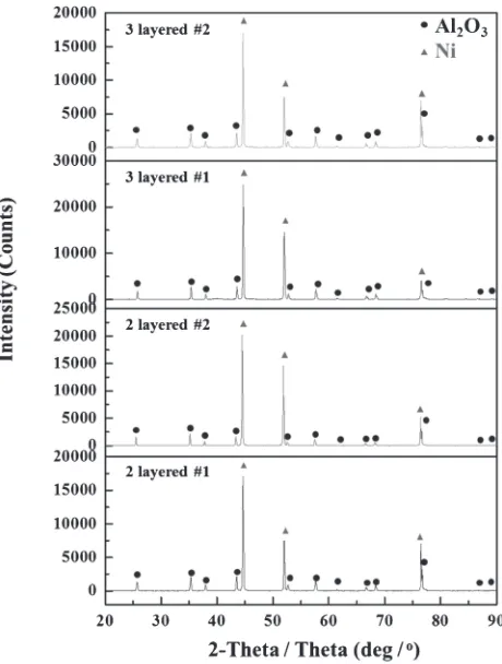
After deposition and drying, the samples were sintered in a pressureless sintering tube furnace (Cermotech Co., Ltd., CTF-A80A, Korea). To reduce NiO to Ni, sintering was conducted in 95%Ar/5%H2atmosphere for reduction based on TGA (TA instrument, SDT Q600, USA) result where phase transformation was observed at the temperature from 300 to 800°C, indicating that NiO was reduced into Ni (Fig. 1(c)). Two different sintering profiles were used to investigate the effect of adding an intermediate sintering step on the microstructures of the FGM coating layers, as shown in Fig. 1. X-ray diffraction (Rigaku, TTR II, Japan) with Cu Ka source was used to verify its reduction of NiO into Ni
and its scanning angle ranged from 20 to 90 degrees. The microstructures were characterized using backscattered scan-ning electron microscopy (BSE, Tescan, Mira 3, Czecho). The mechanical properties of Ni/Al2O3 FGM coating were characterized via nano-indenter (Hysitron, Ubi-1, USA) with its force of 10000 µN.
The resulting compositional gradient of Ni/Al2O3 FGM was verified using an electron probe micro analyzer (Shimadzu, EPMA-1720, Japan).
3. Results and Discussion
3.1 Zeta potential and electrophoretic mobility
Figure 2 shows the zeta potential and electrophoretic mobility data for Ni, NiO, and Al2O3. Although NiO had a higher zeta potential and mobility than that of Ni, these values were close to that of Al2O3. Therefore, NiO is more suitable than Ni for co-deposition.
According to the studies done by Wang and Nicholson,22) the interaction potential energy for the NiO, Al2O3and mixed particles can be calculated by DLVO theory with varying pH conditions. And, according to Verwey and Overbeek,23) the minimum net repulsive energy necessary to stabilize a suspension is 15 kT. Their results showed that decay of the interaction energy with its distance for NiO, Al2O3 and mixed particles are slow for pH in the range of 4 to 5. Thus, NiO and Al2O3mixed suspension can be stabilized at a pH ranging from 4 to 5, which is the optimal pH range for deposition for both single and binary suspensions.
These results were compared with the measured zeta potential and mobility of NiO and Al2O3 in this study. The zeta potential and mobility for NiO and Al2O3 were espe-cially similar at a pH of 4, as shown in Fig. 2. Based on this result, all of our suspensions were adjusted to the pH of 4.
3.2 FGM coating of Ni/Al2O3 composite as a function
of the sintering profile and layers
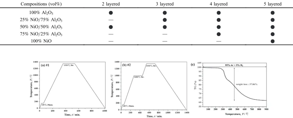
[image:2.595.49.539.86.284.2]To fabricate crack-free and thin FGM coatings of Ni/ Al2O3 composite, two types of sintering profiles were used Table 1 Composition of the fabricated samples.
Compositions (vol%) 2 layered 3 layered 4 layered 5 layered
100%Al2O3
25%NiO/75%Al2O3 ®
50%NiO/50%Al2O3
75%NiO/25%Al2O3 ® ®
100%NiO ® ® ®
to fabricate the samples. Sintering profile#1 had no inter-mediate step, with an increasing temperature up to 1350°C. Sintering profile#2 included an intermediate step at 1000°C for 3 h for coarsening the Ni powders and to obtain the desired FGM microstructure. Using these two profiles, the number of layers was varied, ranging from two tofive, while empirically maintaining the same overall thickness of 20 25 µm.
The first layer in FGM coating layers used in this study was deposited for 5 s with its thickness resulting around 5 µm. Since the former layer increases its resistance of substrate as well as its bonding force betweenfirst layer and substrate, the thickness of the subsequent layers can be varied compared to its thicknesses of the former layers regardless of its same deposition time. Overall, maximum thickness of 2025 µm was achieved for all the samples. This is due to weak bonding force between substrate deposited with 25 layers and depositing materials. Details about the conditions used are provided in Fig. 2 and Table 1.
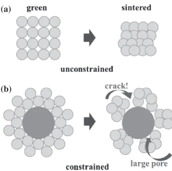
3.2.1 X-ray diffraction
After deposition, a green compact of NiO/Al2O3 was coated on the Ni substrate and sintered in Ar/H2to promote reduction into Ni/Al2O3 composite. Cross sectional area of FGMs coated on Ni substrate was measured using X-ray diffraction to confirm its reduction of NiO to Ni (Fig. 3). XRD pattern exhibits peaks corresponding to Ni (JCPDS# 4-0850) and Al2O3 (JCPDS #10-173). However, Ni peak is a bit stronger than Al2O3 peak because of Ni substrate itself. As a result, no single peak related to NiO was found, demonstrating that its reduction of NiO to Ni has been successful. Thus, XRD analysis indicates that thefinal phase is composed of Ni and Al2O3 under the specified sintering process.
3.2.2 Microstructure of four- and five-layered samples under sintering profile#1
The cross-sectional microstructure of four- and five-layered FGMs were observed by BSE after sintering with profile#1. Figure 4 shows that both samples had its thicknesses about 2025 µm. Cracks were observed near the Ni-rich coating layer for both samples possibly due to sintering stress.24)Figure 5 shows schematics of the sintering stress concept describing crack formation in four- and five-layered samples. Different sizes of particles were sintered where small particles surrounding large particles are present to result in pores, inducing cracks after sintering. Due to its differences in sintering temperatures between Ni and Al2O3, Ni sinters first after NiO powders are reduced to Ni.
Therefore, coarsening of Ni particles is observed before the growth of Al2O3 particles, forming cracks around the particles. Nano-sized particles around micro-sized particles affect the sintering densification of composites significantly. Large structures prevent full densification during sintering due to non-uniform and constrained sintering of the small Fig. 3 X-ray diffraction pattern of Ni/Al2O3FGM samples under the two
sintering profiles.
Fig. 4 Cross-sectional images of (a) four-layered and (b) five-layered samples.
(a) (b)
Mobility
,
µµ
/10
-8cm 2/V
.s
[image:3.595.133.466.71.189.2] [image:3.595.312.542.226.530.2] [image:3.595.307.549.578.667.2]sized particles. This is observed predominantly in the sintering of mostly large particles, resulting in cracks for short sintering times and low sintering temperature. Figure 5 shows how cracks were induced in the Ni-rich area, where large particles are predominant.
During sintering process, NiO shrinks significantly due to its reduction to Ni and formation of Ni powder clusters at lower temperatures than that of Al2O3, due to its lower melting temperature than that of Al2O3. Therefore, significant amount of Ni coarsening was observed in the coating layer close to the Ni-rich region due to its constraining effect, leading to cracks and pores because the stress around Al2O3 particles caused by the highly coarsened Ni particles accumulated, as shown in Fig. 5. This becomes more apparent with increasing vol% of NiO as their sintering is in progress along with reduction to Ni particles as well as agglomeration. As more NiO particles are sintered, more non-uniform and constrained sintering of Al2O3 particles resulted. To overcome these sintering stress and constraining effect problems, Ni-rich layers, such as 100% Ni and 75% Ni/25% Al2O3, which can induce constraining effects, were removed, resulting in fewer layers, as described in the next section.
3.2.3 Microstructure of two- and three-layered sam-ples®cross-sectional images
Figure 6 shows two- and three-layered FGM samples which are used to resolve problems encountered with the four- andfive-layered samples. The layers were coated and sintered with an overall thickness of 2025 µm. The cracks were not induced within the coating layers. However, several differences were encountered with the microstructures depending on the sintering profile. Figures 6(a) and 6(c) shows the microstructures obtained for the two- and three-layered samples under sintering profile#1; there is no gradient within the coating layer. However, for samples sintered under profile#2 with an intermediate step of 1000°C for 3 h, coarsened and clustered Ni particles were observed near Ni substrate, increasing overall contact area between Ni substrate and Ni particles in FGM coating layer. These formed Ni-rich region, contrary to the samples sintered under profile#1, as shown in Figs. 6(b) and 6(d). As shown in
Figs. 6(a) and 6(c), the interface between Ni substrate and FGM coating layer was abrupt since hardly no contact area between Ni substrate and Ni particles in FGM coating layer was observed. Therefore, samples sintered under profile#1 showed an abrupt interface between the Ni substrate and FGM layers. However, under sintering profile#2, the interface between Ni substrate and FGM was smooth and showed a gradient profile. Therefore, it was found that the intermediate step in the sintering profile helped to make a smooth transition between the Ni substrate and FGM coating layers by controlling its coarsening of the powders.
3.2.4 Surface images of two- and three-layered samples Figure 7 shows SEM images of FGM coating layers. Many surface cracks were observed for the two-layered sample under sintering profile#1 (Fig. 7(a)). However, the number of cracks decreased significantly when samples were sintered under sintering profile#2 with its intermediate step (Fig. 7(b)). The intermediate temperature was not sufficient to induce necking among Al2O3powders, but it relieved the residual stresses within the coating layer during the sintering (a)
(b)
Fig. 5 Schematic diagram of the sintering stress concept describing crack formation in four- andfive-layered samples; (a) single component system
(b) double component system with different in size. Fig. 6profileCross-sectional images of two-layered samples under (a) sintering#1 and (b) sintering profile#2, and three-layered samples under (c)
sintering profiles#1 and (d) sintering profile#2.
[image:4.595.82.254.67.238.2] [image:4.595.307.548.69.250.2] [image:4.595.307.547.308.489.2]process. Adding more layers significantly reduced the number of cracks, as shown in the three-layered samples. The compositional change became smooth as more layers were added; it seems that the residual stress was reduced, minimizing the crack formation. Therefore, the three-layered sample with sintering profile#2, which included the intermediate sintering step of 1000°C for 3 h, represented the most optimum conditions that lead to the least number of cracks.
3.3 Mechanical characterization
The hardness was measured with an interval of 2 µm along the compositional gradient for its mechanical character-ization. Per each indent, 5 points were taken around that position to calculate average values as shown in Figs. 8(a) and 8(b). The average size of indent is about 1 µm in size and these indents shown in Fig. 8(c) were taken in the middle of the FGM coating layer which these indents cover both Ni and Al2O3in the coating layer.
Figure 8(a) shows the hardness results of the three-layered samples under different sintering profiles. The samples fabricated under sintering profiles #1 and #2 showed a decreasing trend of hardness from Al2O3-rich to Ni-rich
layers, but the hardness near Ni-rich region showed different trend. In other words, the hardness was constant near the Ni-rich area for the sample sintered under profile#1, whereas the sample sintered under profile#2 showed a decreasing trend in hardness, as expected. The microstructure of the three-layered sample sintered under sintering profile#1 had no gradient near the Ni substrate (see Fig. 6(c)), which explains why the hardness did not change near the Ni-rich area. However, under sintering profile#2 with its intermedi-ate sintering step, Ni particles were clustered and coarsened near the Ni substrate. Therefore, the hardness around the Ni-rich region decreased. Figure 8(b) compares the hardness of the two- and three-layered samples under sintering profile#2. The hardness of the three-layered sample was higher than that of the two-layered sample, with the hardness of the three-layered sample being higher than that of any other sample, due to the uniform coating layer.
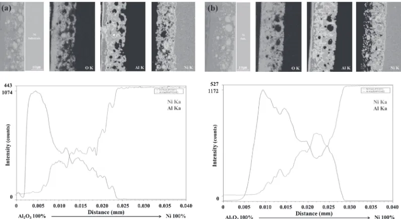
3.4 EPMA analysis of two- and three-layered samples under sintering profile#2
EPMA was used to map the material composition across the gradient layers of two- and three-layered samples under sintering profile#2, as shown in Fig. 9. Gradients were
(a) (b) (c)
Fig. 8 Comparison of the hardness results for (a) three-layered samples with sintering profiles#1 and#2, (b) two- and three-layered samples under sintering profile#2 and (c) AFM (Atomic Force Microscopy) image of indents.
[image:5.595.98.501.73.199.2] [image:5.595.100.498.251.469.2]formed successfully for these samples through coarsening process. This analysis shows that FGM between Ni and Al2O3 has been successfully fabricated with gradient in composition from one end to the other without forming any intermediate compound, such as NiAl2O4. The intermediate layers shown in Fig. 9 detect Ni, Al and O since these layers have varying compositions of Ni and Al2O3from one end to the other.
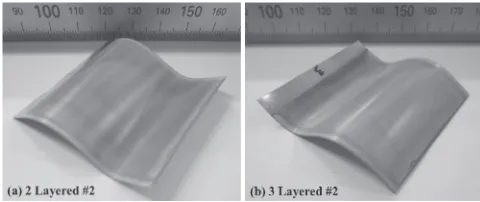
Figure 10 shows optical images of the optimized FGM-coated layers on Ni substrates. As shown in the figure, these FGM-coated layers were bent successfully without any delamination and crack formation.
4. Conclusions
Ni/Al2O3 functional gradient material (FGM) coating layers with overall coating thicknesses of 2025 µm were fabricated using pulsed DC EPD. The sintering profiles and number of layers were varied to find the optimized coating layer. Coatings with two and three layers had no internal cracks, whereas those with four and five layers had several internal cracks due to the constraining effects between Al2O3 and Ni particles. Moreover, samples sintered under a profile with an intermediate step at 1000°C for 3 h formed gradients within the coating layers through diffusion due to Ni coarsening during sintering. The number of cracks on the coating surface was reduced significantly using two- and three-layered samples. Therefore, controlling its sintering conditions with an intermediate step and changing the number of layers, are important factors that allow us to obtain crack-free coatings. The three-layered sample with the intermediate sintering step (profile#2) at 1000°C for 3 h provided the optimum coating conditions, as determined by comparing microstructures, hardness, and the results from an electron probe micro analyzer (EPMA). Therefore, crack was minimized on the FGM coatings were fabricated by pulsed DC EPD by controlling sintering profile and the number of layers.
Acknowledgments
This research was supported by Basic Science Research Program through the National Research Foundation of Korea (NRF) funded by the Ministry of Education, Science and Technology (NRF-2012R1A1A3004290), by an NRF grant (#2011-0029862) funded by MEST, and by the Human Resources Development program (No. 20124030200130) of the Korea Institute of Energy Technology Evaluation and Planning (KETEP) grant funded by the Korea Government Ministry of Trade, Industry and Energy.
REFERENCES
1) S. Suresh and A. Mortensen:Fundamentals of Functionally Graded Materials: Processing and Thermomechanical Behaviour of Graded Metals and MetalCeramic Composites, (University Press, Cambridge, 1998).
2) Y. Miyamoto, W. A. Kaysser, B. H. Babin, A. Kawasaki and R. G. Ford: Functionally Graded Materials: Design, Processing and Applications, (Kluwer Academic Publishers, Boston, 1999). 3) C. S. Lee, L. C. De Jongh and G. Thomas:Acta Mater.49(2001)
37673773.
4) H. A. Bruck:Int. J. Solids Struct.37(2000) 63836395.
5) S. K. Yang, H. S. Kim and C. S. Lee:Ceram. Int.39(2013) 9399. 6) L. Besra and M. Liu:Prog. Mater. Sci.52(2007) 161.
7) T. Hirai: Processing of Ceramics Part 2, Materials Science and Technology17B, (Verlagsgesellschaft, Weinheim, 1996).
8) B. Ferrari, S. González, R. Moreno and C. Baudin: J. Eur. Ceram. Soc.
26(2006) 736.
9) O. O. Van der Biest and L. J. Vandeperre:Rev. Mater. Sci.29(1999) 327352.
10) I. Corni, M. P. Ryan and A. R. Boccaccini:J. Eur. Ceram. Soc. 28 (2008) 13531367.
11) A. R. Boccaccini and I. Zhitomirsky:Curr. Opi. Sol. Stat. Mat. Sci.6 (2002) 251260.
12) C. Kaya, F. Kaya, A. R. Boccaccini and K. K. Chawla:Acta Mater.49 (2001) 11891197.
13) I. Zhitomirsky and A. Pertic: J. Am. Ceram. Soc.20(2000) 20552061. 14) C. Kaya, F. Kaya and A. R. Boccaccini:J. Mater. Sci.37(2002) 4145
4153.
15) X. Zhigang, R. Gukan, S. Jag and P. Devdas:Surf. Coat. Tech.201 (2006) 44844488.
16) S. Nobuyoshi, K. Masaharu, N. Koshichi, Y. Noriyuki and Y. Masahito: Phys. C. Supercond.357360(2001) 10191022.
17) L. Besra, T. Uchikoshi, T. S. Suzuki and Y. Sakka:J. Am. Ceram. Soc. 91(2008) 31543159.
18) L. Besra, T. Uchikoshi, T. S. Suzuki and Y. Sakka:J. Eur. Ceram. Soc. 29(2009) 18371845.
19) L. Besra, T. Uchikoshi, T. S. Suzuki and Y. Sakka:J. Eur. Ceram. Soc. 30(2010) 11871193.
20) A. R. Boccaccini, J. Cho, T. Subhani, C. Kaya and F. Kaya:J. Eur. Ceram. Soc.30(2010) 11151129.
21) S. C. Wang and B. C. Huang:Thin Solid Films517(2008) 12451250. 22) G. Wang and P. S. Nicholson:J. Am. Ceram. Soc.84(2001) 12501256. 23) E. J. W. Verwey and J. Th. Overbeek: Theory of the Stability of
Lyophilic Collids, (Elsevier, Amsterdam, 1948).
[image:6.595.48.288.70.171.2]24) R. M. German:Sintering Theory and Practice, (John Wiley & Sons, New York, 1996).