Effects of
α
Phase Nucleating at Transition Phase and Dislocation on Mechanical
Properties in Metastable
β
Titanium Alloy Ti-6.8Mo-4.5Fe-1.5Al
*1Tatsuaki Sakamoto
1, Kazuki Takiue
1,*2, Yuri Higaki
1,*3, Sengo Kobayashi
1and Kiyomichi Nakai
1,2,*41Department of Materials Science and Biotechnology, Graduate School of Science and Engineering, Ehime University, Matsuyama 790–8577, Japan
2Miura Co., Ltd., Matsuyama 799–2696, Japan
Effects of α phase nucleating at a transition phase and dislocation on mechanical properties in a metastable β titanium alloy, Ti-6.8Mo-4.5Fe-1.5Al(mass%), were investigated. Tensile test and optical, scanning, and transmission electron microscopy were used. Two-step aging promoted the precipitation of a fine α phase in grain interiors because the α phase nucleated at a transition phase of β′. A precipitation-free zone
appeared at first, but finally disappeared during aging. A specimen that included the precipitation-free zone showed lower yield strength and larger elongation than it did without the precipitation-free zone. This was because dislocation could easily glide in the precipitation-free zone, which was verified from examination of the intergranular ductile fracture surface. The transition phase of β′ promoted the disappearance of a
precipitation-free zone, due to the promotion of α phase precipitation, resulting in enhancement of yield strength and deterioration of elongation. It is likely that the width of PFZ and the crystallographic orientation of β grains determine fracture mode to be intergranular ductile, intergran-ular brittle or intragranintergran-ular fractures. Aging after tensile deformation produced α phase precipitation at dislocation. A specific variant of α phase was selected due to a stress field around the dislocation that included a planar slip band. This resulted in the formation of a large colony of the specific α variant, while elongation deteriorated because the large colony probably facilitated crack propagation.
[doi:10.2320/matertrans.M2016382]
(Received October 27, 2016; Accepted April 24, 2017; Published June 2, 2017)
Keywords: β titanium alloy, mechanical property, aging, β′ phase, dislocation
1. Introduction
Metastable β titanium alloys are used as materials for man-ufacturing aerospace, automotive, and other products because of their high specific strength1,2).
In this kind of alloy system, precipitation of α phase from a metastable β matrix leads to precipitation strengthening, whereby strength and toughness of the alloys can be con-trolled. Precipitation of α phase is so important that a great deal of research has been conducted on processing and heat treatments that can control precipitation3–8). In the literature,
it has been reported that precipitation of α phase is affected by transition phases (ω phase9,10), β′ phase11,12)) and
disloca-tion13,14).
The α phase, when it is nucleated at a transition phase, is more refined than when it is not nucleated in the transition phase9–12). ω phase precipitates in TIMETAL®LCB
(Ti-6.8Mo-4.5Fe-1.5Al(mass%)), which is one of the metastable
β titanium alloys15,16). It was reported that a refined α phase
precipitated at ω phase in Ti-6.8Mo-4.5Fe-1.5Al9). On the
other hand, our group reported that two-step aging, which consists of the first aging at 300 C, followed by the second aging at 500 C, promoted α phase precipitation and refined the α phase. This most likely occurred when the β′ phase formed at the second step of the aging, serving as a nucleation site for α phase17). The proposed mechanism for the
precipi-tation of the β′ phase is as follows. During the first aging step at 300 C, ω phase precipitated from the β matrix. The second
aging step at 500 C gave rise to reverse transformation ω → β
that resulted in compositional fluctuation in the β matrix. It is suggested that phase decomposition occurred in the region rich in β stabilizers, resulting in the formation of β′ phase17).
Precipitation of α phase is affected by dislocation. Furuha-ra et al. reported precipitation of α phase on dislocation in detail13). They reported in their research that a stress field
around dislocation caused a variant selection. The specific variant, which had a Burgers crystallographic orientation re-lationship with the matrix, was selected to accommodate the stress field around dislocation.
However, no information has been obtained on the strength and elongation of Ti-6.8Mo-4.5Fe-1.5Al, which is subjected to two-step aging and includes an α phase precipitation on dislocation. In this paper, tensile tests of these specimens were performed. Effects of microstructures on mechanical properties at room temperature were investigated.
2. Experimental Procedure
A bar of Ti-6.8Mo-4.5Fe-1.5Al(mass%), that was 12 mm in diameter, was supplied from Titanium Metals Corporation (TIMET) via Nippon Steel Corporation (presently Nippon Steel & Sumitomo Metal Corporation). The chemical compo-sition of the Ti-6.8Mo-4.5Fe-1.5Al bar is shown in Table 1. Specimens were cut from this bar and subjected to the follow-ing two kinds of heat treatments: (1) two-step agfollow-ing and (2) aging after tensile deformation to introduce dislocation. A
*1 This Paper was Originally Published in Japanese in J. Japan Inst. Met.
Mater. 79 (2015) 651–656.
*2 Graduate Student, Ehime University
*3 Graduate Student, Ehime University, Present address: Nippon Steel &
Sumikin Technology Co., Ltd., Futtsu 293–0011, Japan
*4 Emiretus Professor, Ehime University
Table 1 Chemical composition of Ti-6.8Mo-4.5Fe-1.5Al (mass%).
schematic illustration of the heat treatments is shown in Fig. 1. The heat treatments were carried out using an electric furnace in which Ar gas was flowing. In the case of two-step aging, a specimen (about 3 mm thick) was cut from the bar and subjected to solid solution treatment at 850 C for 1.5 ks, held at 300 C for 2 ks, then 500 C at 0.5 and 2 ks, followed by quenching in iced brine. For comparison, an aging treat-ment without the first aging at 300 C (named as one-step ag-ing) was carried out. In two-step aging, cooling from a solid solution treatment at 850 C to the first aging at 300 C gives a specimen an experience at 500 C. However, this effect was not significant in the present study because a specimen sub-jected to the first aging at 300 C, without the second aging, showed the same microstructure as a specimen subjected to solid solution treatment, followed by iced-brine quenching and, then, aging treatment at 300 C. The microstructure was fine precipitates of ω phase in a β matrix18). Therefore, the
cooling rate from the solid solution treatment to 300 C was rapid enough to suppress the effect of the experience at 500 C. In the case of aging, after the tensile test, a specimen had a 1.5 mm-thick plate shape, with a width of 3 mm, and a gauge length of 10 mm. This tensile specimen was subjected to sol-id solution treatment at 850 C for 1.5 ks, followed by quench-ing in iced brine. Subsequently, the specimen was given 5% of a plastic strain, at a strain rate of 1 × 10⁻⁴ s−1 at room
temperature, by using a tensile testing machine (Shimadzu, AG-10kNI). The deformed specimen was subjected to aging at 500 C for 2 ks, followed by iced brine quenching. Follow-ing two kinds of heat treatment, the microstructure was ob-served by using optical microscopy after the specimen had been etched with a solution of 3 ml HF, 5 ml HNO3, and
100 ml H2O. A specimen for transmission electron
microsco-py (TEM) by JEM-100CXII and JEM-2000EX, operated at 100 kV and 200 kV, respectively, was made by the twin-jet method using a solution of 25 ml HClO4, 180 ml C4H7OH,
and 300 ml CH3OH at 25 V at −40 to −50 C. The tensile test
was performed at room temperature with a strain rate of 1 ×
10−4 s−1. A fracture surface, after the tensile test, was
ob-served with scanning electron microscopy (SEM) by AL-PHA-25A (TOPCON) and operated at 15 kV.
3. Results and Discussions
3.1 Two-step aging
Figure 2 shows optical micrographs of the specimens after one-step and two-step agings. Figure 2(a) and (c) are micro-structures of one-step aging for 0.5 and 2 ks; (b) and (d) are those for the second step of two-step aging for 0.5 and 2 ks, respectively. In the specimens, after one-step and two-step agings for 0.5 ks, fewer precipitates of α phase could be seen in the one-step aged specimen than in the two-step aged spec-imen. The precipitation-free zone (PFZ) in the one-step aged specimen was wider than that in the two-step aged specimen. The α phase in the one-step aged specimen precipitated in β
phase in granular contrast, whereas α phase in the two-step aged specimen precipitated in homogeneous contrast instead of granular contrast. This means that a lot of fine α phase precipitated homogeneously in the two-step aged specimen. After aging for 2 ks, the PFZ in both specimens almost disap-peared.
There is a question concerning whether the PFZ of α phase, which precipitates within β grains during two-step aging, co-incides with the PFZ of β′ phase since α phase is believed to nucleate at β′ phase. Unfortunately, this question is currently unclear. The β′ phase is considered to be formed by phase separation in a region where the β stabilizer is enriched. Therefore, the PFZ of the β′ phase is probably influenced by a concentration of β stabilizer near a grain boundary. If the formation of a grain-boundary α phase precedes the forma-tion of a β′ phase, enrichment of a β stabilizer near the grain boundary probably influences the formation of the β′ phase. This may result in the formation of PFZ of the β′ phase. How-ever, the PFZ of α phase may be formed, irrespective of the existence of PFZ of the β′ phase. The PFZ of α phase is con-sidered to be formed because α stabilizer near a grain bound-ary decreases due to the formation of a grain-boundbound-ary α
phase19). Therefore, even in a case where the β′ phase
precip-Fig. 2 Optical micrographs of specimens after (a, c) one-step and (b, d) two-step aging at 500 C for (a, b) 0.5 ks and (c, d) 2 ks.
[image:2.595.66.269.530.753.2] [image:2.595.305.547.570.757.2]itates near a grain boundary (i.e., PFZ of the β′ phase does not exist), the PFZ of α phase may be formed if α stabilizer de-creases due to formation on the grain-boundary of α phase. As for relationship of width of PFZ between β′ and α phases, two cases are possible as follows, although the existence of PFZ of β′ phase is unclear. One is a case where β′ phase is formed within a region where α stabilizer is lean due to the existence of a grain boundary α phase, and the other is a case where β′ phase is not formed there. A case where PFZ of β′ phase does not exist is included in the former case. In the former case, when α phase starts to precipitate in the two-step aged specimen, a width of PFZ of α phase is probably smaller or equal as compared with that in a case where β′ phase would not be formed in the two-step aged specimen (i.e., as com-pared with a width of PFZ of α phase in the one-step aged specimen at the beginning of the α precipitation). α phase in the one-step aged specimen starts to precipitate late after the
α phase precipitation in the two-step aged specimen. When the α phase in the one-step aged specimen starts to precipi-tate, the width of PFZ of α phase in the two-step aged speci-men is smaller than that in the one-step aged specispeci-men. Therefore, after prolonged aging, the width of PFZ of α phase in the two-step aged specimen is likely to be smaller than that in the one-step aged specimen. In the latter case, when α
phase starts to precipitate in the two-step aged specimen, a width of PFZ of α phase is probably equal to a width of PFZ of β′ phase (i.e., is larger or equal as compared with that in a case where β′ phase would not be formed in the two-step aged specimen). α phase in the one-step aged specimen starts to precipitate late after the α phase precipitation in the two-step aged specimen. When the α precipitation in the one-step aged specimen starts, if the width of PFZ of α phase in the two-step aged specimen is smaller than that in the one-step aged spec-imen (i.e., α phase precipitation in the two-step aged speci-men is promoted so that the width of PFZ of α phase in the two-step aged specimen can become smaller than that in the one-step aged specimen), the width of PFZ of α phase in the two-step aged specimen after prolonged aging is likely to be smaller than that in the one-step aged specimen. In any case as described above, the width of the PFZ of α phase in the two-step aged specimen in Fig. 1 is smaller than that in the one-step aged specimen since the precipitation of α phase within the β grain is promoted because the β′ phase acts as a nucleation site for α phase.
Figure 3 shows TEM micrographs of these specimens. These micrographs are dark field images taken with 10¯10 re-flection. Diffraction patterns taken from Fig. 3(a) (d) show the existence of α phase with Burgers orientation relationship (Type 1α) and without Burgers orientation relationship (Type 2α20)). An objective aperture includes reflections of these α
phases. Therefore, the dark field images in Fig. 3(a) (d) in-clude variants of Type 1α and Type 2α. Variants, which are not shown in the dark field images in Fig. 3(a) (d), are con-sidered to be equivalently formed to the other variants. In the specimen aged for 0.5 ks, more α phases were formed in the two-step aged specimen in (b) than in the one-step aged spec-imen in (a). This result is consistent with that obtained by optical microscopic observation (Fig. 2(a), (b)). In the speci-men that was aged for 2 ks, α phase can be seen throughout the grains, and α phase is smaller in the two-step aged
speci-men than in the one-step aged specispeci-men. The α phase had a lath shape. Also, the α phase in the specimen aged for 2 ks was wider and longer than that in the specimen aged for 0.5 ks. This trend was more prevalent in the one-step aged specimen than it was in the two-step aged specimen.
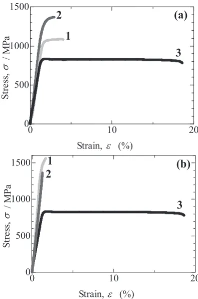
Figure 4 shows results of tensile tests of these specimens. Figure 4(a) shows stress-strain curves for specimens aged at 500 C for 0.5 ks in the one-step aging and the two-step aging. For comparison, Fig. 4(a) also shows the result using only solid solution treatment for a specimen. In the solution-treat-ed specimen, whose microstructure is β phase throughout the specimen, the yield strength was 825 MPa and the plastic
Fig. 3 Dark field images of specimens after (a, c) one-step and (b, d) two-step aging at 500 C for (a, b) 0.5 ks and (c, d) 2 ks.
[image:3.595.305.547.237.413.2] [image:3.595.326.524.463.761.2]strain was 17%. In the one-step and two-step aged specimens, the yield strengths were 1047 and 1243 MPa, and the plastic strain was 2.5 and 1.5%, respectively. It is noted that precipi-tation strengthening was more significant in the two-step aged specimen than in the one-step aged specimen. This re-sult is consistent with the fact that optical microscope and TEM observations showed that the precipitation of α phase was promoted in the two-step aged specimen, and is consis-tent with the resulting Vickers hardness that was reported by our group17). The hardness in the two-step aged specimen was
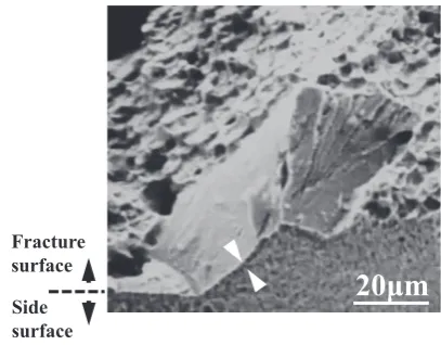
larger than that in the one-step aged specimen. In the stress-strain curves of specimens for 2 ks (Fig. 4(b)), the yield strength and plastic strain were 1471 MPa and 0.52% in the one-step aged specimen, whereas the two-step aged specimen broke within the limit of elasticity. In order to investigate and determine the reason for such mechanical properties, the frac-ture surface was observed using SEM, as shown in Fig. 5. In the one-step and two-step aged specimens for 0.5 ks as shown in Fig. 5(a) and (b), respectively, the fracture surface exhibit-ed the shape of β grains, and dimples could be seen on the surface of the fracture. This indicates that the ductile fracture occurred along the β grain boundary. On the other hand, for 2 ks, the one-step and two-step aged specimen fracture sur-faces (Fig. 5(c) and (d), respectively) did not necessarily ex-hibit shapes of β grains, and the dimples showed intragranular fractures in β phase. Besides, a flat surface without dimples was also observed in Fig. 5. In order to investigate the flat surface, a specimen subjected to the one-step aging at 500 C for 2 ks was observed by SEM, as shown in Fig. 6. The spec-imen was observed obliquely in order to observe both the fracture and the side surfaces. On the side surface, the grain-boundary α phase was observed in band-like contrast (as indicated by the white arrow) and the granular contrast of
α phase within β grain could be seen. A region showing a flat surface on the fracture surface corresponded to the grain-boundary α phase on the side surface. A region that showed dimples on the fracture surface corresponded to that which did not show a band-like contrast of the grain-bound-ary α phase on the side surface, that is, this region corre-sponded to the grain interior. In a TEM micrograph, taken of a region that included a grain boundary, the α phase was
[image:4.595.322.526.381.540.2]ob-served along the grain boundary as shown in Fig. 7. It is be-lieved that most β grain boundaries were covered with grain-boundary α phases because PFZ could be observed along almost all the β grain boundaries as can be seen in Fig. 2.
Based on the results above, the following was determined. PFZ forms near β grain boundaries in both one-step and two-step aged specimens during the early stages of aging. Tensile deformation exerted on a specimen where PFZ exists pro-motes deformation by facilitating the motion of dislocation in the PFZ21). As the localized deformation in the PFZ proceeds,
accumulation of dislocations occurs, resulting in ductile frac-ture due to formation and connection of voids along the β
grain boundaries. The ductile fracture within the PFZ along the β grain boundaries gives rise to the formation of dimples. At the late stage of aging, β grains are covered with α phase and the PFZ disappears. Then, intragranular fracture occurs significantly. Intergranular brittle fracture also occurs due to the accumulation of dislocations at the interface between grain-boundary α phase and β phase and the formation and propagation of cracks, which acts as an initiation point of fracture22). It is believed that, at the early stage of aging where
the formation of grain-boundary α phase is not significant, the frequency of occurrence of intergranular brittle fracture
Fig. 7 (a) Bright and (b) dark field images including grain boundary for a specimen after one-step aging at 500 C for 2 ks.
Fig. 5 SEM micrograph of fracture surfaces for specimens after (a, c) one-step and (b, d) two-one-step aging at 500 C for (a, b) 0.5 ks and (c, d) 2 ks.
[image:4.595.48.289.594.760.2] [image:4.595.307.549.599.758.2]lowers, but this is a matter for future work. The determination of the occurrence of intergranular ductile fracture or inter-granular brittle fracture probably depends on the extent of accumulation of dislocations in PFZ or at the interface be-tween grain-boundary α phase and β phase. It is considered that intergranular ductile fracture occurs due to the formation of voids within a grain (that is, within the PFZ) near the grain boundary, whereas intergranular brittle fracture occurs due to the formation of cracks by dislocations accumulating at the grain boundary. At which site the accumulation of disloca-tions occurs is probably determined by the geometrical con-figuration of the grains. The question has not yet been clari-fied, but is a topic for future work. However, irrespective of the occurrence of accumulations of dislocations at grain inte-riors or at grain boundaries, the decrease in the width of PFZ probably promotes an accumulation of dislocations due to the multiplication of dislocations in narrow regions. Therefore, the two-step aged specimen fractures more quickly than the one-step aged specimen does because the formation of cracks in the two-step aged specimen is promoted due to decreases in the width of PFZ where dislocations are allowed to move easily. The decrease in the width of PFZ in the two-step aged specimen occurs since the formation of α phase is promoted by the formation of β′ phase, which acts as a nucleation site for α phase.
3.2 Aging after tensile test
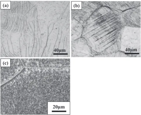
Figure 8 shows optical micrographs taken before and after aging following tensile tests. Figure 8(a) shows the micro-structure before aging, following the tensile test, as well as slip bands in almost parallel configuration in the β grain. Bhattacharjee et al. also reported similar findings. They ob-served dislocations by TEM using a specimen where a slip band could be observed, and reported a planar slip of disloca-tions23). Also in their literature, the planar slip was the
prima-ry cause of the low work hardening rate. This can be seen in the stress-strain curve (No.3 in Fig. 4), where a specimen that included a single β phase had a low work-hardening rate.
Fig-ure 8(b) is the microstructFig-ure after aging following the tensile test. It is noted that the α phase in a straight shape could be observed by etching. The β grain was principally covered with a straight α phase that had grown in one direction. Due to a little weak etching, not all the α phases were observed. On the other hand, while Fig. 8(c) shows a microstructure af-ter aging without a tensile deformation, a straight contrast of
α phase as shown in Fig. 8(b) was not observed even though granular contrast could be seen throughout the β grain. Amount of the precipitation in Fig. 8(b) is likely to be same as that in Fig. 8(c) because the aging at 500 C for 2 ks leaded to almost saturation of Vickers microhardness in a specimen aged without tensile deformation17). The specimen aged after
tensile deformation also is likely to show the saturation of Vickers microhardness because the precipitation of α phase is promoted by the dislocation that was introduced by deforma-tion24). Figure 9 shows TEM micrographs for these
speci-mens. Figures 9(a) and (b) are dark field micrographs taken of specimens after aging following a tensile test, and after aging without a tensile test, respectively. In Figs. 9(a) and (b), various variants were included as shown in Fig. 3. A speci-men aged after a tensile test showed an α phase that had grown in only one direction in a wide region, whereas a spec-imen aged without a tensile test showed an α phase that had grown in various directions. In Fig. 9(a), several variants probably exist, but a specific variant was predominantly grown and observed. It is noted that in a specimen aged after a tensile test, a specific variant of α phase was selected and formed a large colony. The optical micrographs in Fig. 8(c) do not depict a straight contrast of the α phase because vari-ous variants of the fine α phase grow, resulting in homoge-neous granular contrast. As for a reason for the selection of a specific variant, Furuhara et al. reported that a particular vari-ant was chosen so that the strain field around the dislocation could be accommodated13). Accordingly, a specific variant
was also selected for the present study so that the strain field around the dislocation introduced by tensile deformation could be accommodated. It is considered that an aggregate of
α phases, which were parallel with one another, formed be-cause many dislocations were parallel due to a planar slip. This resulted in the formation of a large colony of α phase. In Fig. 8(b), a large colony can be seen in the grain at the center of the figure. In the region that was not sufficiently etched, other colonies of other variants of α phase were probably
Fig. 8 Optical micrographs of (a) a deformed specimen, (b) an aged speci-men aged after tensile deformation, (c) an aged specispeci-men without tensile deformation.
[image:5.595.48.290.553.750.2] [image:5.595.307.547.619.760.2]formed. This other variant could accommodate the strain field of a different dislocation from the dislocation whose strain field was accommodated by the large colony in the grain at the center of the figure. Different kinds of dislocations can be seen in Fig. 8(a), such as the group of dislocations at the up-per left corner of the figure and the group at the lower side of the figure. The width of the α laths precipitating at dislocation in Fig. 9(a) were smaller than those in Fig. 9(b) because the α
laths in Fig. 9(a) nucleated at a higher rate due to nucleating in dense dislocations.
Figure 10 shows the stress-strain curves of these mens. Figure 10(a) depicts a stress-strain curve for a speci-men after solution treatspeci-ment, 10(b) is after aging following tensile deformation, and 10(c) is after aging without tensile deformation. As for the solution treated specimen described above, the yield strength was 825 MPa and the plastic strain was 17%. On the other hand, the specimen after aging with-out tensile deformation had a yield strength of 1471 MPa and the plastic strain was 0.56%. This specimen was strengthened by the precipitation strengthening of α phase, although duc-tility decreased. In the specimen after aging following tensile deformation, the specimen fractured within the limit of elas-ticity. SEM observations of these specimens are shown in Fig. 11. As seen in Fig. 11(a), an intragranular fracture oc-curred in a specimen after solution treatment with dimples
observed throughout the fracture surface. On the other hand, in the specimen after aging following tensile deformation, many regions of cleavage fracture were observed along a cer-tain crystallographic plane. On the fracture surface, parallel striped contrast could be seen. It is considered that this stripe contrast corresponded to the interfaces between α phases be-cause the cleavage traversed a colony of parallel α phases. In the specimen after aging without tensile deformation, intra-granular fracture with dimples and interintra-granular brittle frac-ture with flat fracfrac-ture surface were observed.
Based on the results above, a specific variant of α phase was selected in a specimen after aging following tensile de-formation. The selected α phase formed a colony. The paral-lel arrangement of the α phases facilitated crack propagation. Cleavage fracture easily occurred along a certain plane of the
α phase across the colony, resulting in a brittle fracture in the limit of elasticity. As for a grain-boundary α phase, the effect of dislocations on the formation of grain boundary α phase is unknown in the specimen aged following the tensile deforma-tion. It is believed that there exist grain-boundary α phases due to large grain-boundary diffusion coefficient and high grain-boundary energy. However, the cleavage fracture sur-face in Fig. 11(b) suggests that the colony of the α phases al-lowed the cleavage fracture to occur very easily even if there existed grain-boundary α phases on β grain boundaries with-out PFZ of α phase.
4. Conclusion
Tensile tests were performed using two kinds of specimens of a metastable β titanium alloy, Ti-6.8Mo-4.5Fe-1.5Al(mass%). One was subjected to two-step aging, and the other was subjected to aging after tensile deformation. The former treatment provided the formation of β′ phase and the latter introduced dislocation. β′ phase and dislocation acted as a nucleation site for α phase. Two-step aging promoted pre-cipitation of α phase, but lowered plastic strain. A specimen in the early stage of two-step aging showed higher ductility than that in the late stage of two-step aging because PFZ was responsible for ductility, resulting in an intergranular ductile fracture. Disappearance of PFZ in the latter part of two-step aging provided significant intragranular fracture. It is noted that the β′ phase promoted the precipitation of α phase and improved strength, whereas the β′ phase promoted a decrease in PFZ and deterioration of ductility. Intergranular brittle fracture was observed irrespective of aging time. This frac-ture was due to the grain-boundary α phase. Three kinds of fracture surface were observed in the one-step and two-step aged specimens: intergranular ductile, intergranular brittle and intragranular fractures. It is likely that the width of PFZ and the crystallographic orientation of β grains determine which fracture mode is activated.
[image:6.595.69.268.399.546.2]Aging after tensile deformation also increased yield strength by precipitation strengthening and decreased plastic strain. In a specimen subjected to this aging, the specific vari-ant of α phase that was selected formed a large colony where crack easily propagated so that a cleavage fracture occurred along a certain crystallographic plane of α phase, resulting in a fracture within the limit of elasticity.
[image:6.595.49.291.604.752.2]Fig. 10 Stress-strain curves of specimens (a) after solution treatment, (b) aged after tensile deformation and (c) aged without tensile deformation.
Acknowlegement
The authors would like to express their gratitude to TIMET and Nippon Steel & Sumitomo Metal Corporation for supply-ing experimental specimens and to Integrated Center for Sci-ence (presently Advanced Research Support Center) of Ehime University for utilizing the TEM of JEM-2100 in the present study. A part of this work was supported by Ehime University as a research for seeds of science and technology for industry and by Grants-in-Aid for Scientific Research (No. 21760559).
REFERENCES
1) R.R. Boyer: Mater. Sci. Eng. A 213 (1996) 103–114.
2) Y. Kosaka, S.P. Fox, K. Faller and S.H. Reichman: J. Mater. Eng. Per-form. 14 (2005) 792–798.
3) Y.G. Zhou, W.D. Zeng and H.Q. Yu: Mater. Sci. Eng. A 393 (2005) 204–212.
4) X. Wu, J. del Prado, Q. Li, A. Huang, D. Hu and M.H. Loretto: Acta Mater. 54 (2006) 5433–5448.
5) G.T. Terlinde, T.W. Duelig and J.C. Williams: Metall. Trans., A, Phys. Metall. Mater. Sci. 14 (1983) 2101–2115.
6) P. Ganesan, G.A. Sargent and R.J. de Angelis: J. Mater. Sci. 15 (1980) 1425–1435.
7) J.T. Kandra, C.E. Neu, S.L. Opet and W.E. Frazier: Scr. Metall. Mater. 31 (1994) 243–248.
8) O.M. Ivasishin, P.E. Markovsky, S.L. Semiatin and C.H. Ward: Mater.
Sci. Eng. A 405 (2005) 296–305.
9) F. Prima, P. Vermaut, G. Texier, D. Ansel and T. Gloriant: Scr. Mater. 54 (2006) 645–648.
10) Y. Ohmori, H. Natsui and K. Nakai: Mater. Trans., JIM 39 (1998) 49– 56.
11) M. Okada: Tetsu-to-Hagané 76 (1990) 614–621.
12) T. Furuhara, T. Makino, Y. Idei, H. Ishigaki, A. Takada and T. Maki:
Mater. Trans., JIM 39 (1998) 31–39.
13) T. Furuhara, H. Nakamori and T. Maki: Mater. Trans., JIM 33 (1992) 585–595.
14) T. Furuhara and T. Maki: Mater. Sci. Eng. A 312 (2001) 145–154.
15) F. Prima, P. Vermaut, T. Gloriant, J. Debuigne and D. Ansel: J. Mater. Sci. Lett. 21 (2002) 1935–1937.
16) J. Debuigne and F. Prima: Mater. Trans. 46 (2005) 1433–1435.
17) T. Sakamoto, Y. Higaki, S. Kobayashi and K. Nakai: Mater. Sci. Forum 638–642 (2010) 461–464.
18) T. Sakamoto, Y. Higaki, S. Kobayashi and K. Nakai: J. the Japan Soci-ety for Heat Treatment 49 (2009) 800–803.
19) C. Li, J. Chen, W. Li, J.J. He, W. Qiu, Y.J. Ren, J.L. Chen and J.H. Chen: J. Alloy. Compd. 627 (2015) 222–230.
20) C.G. Rhodes and J.C. Williams: Metall. Trans., A, Phys. Metall. Mater. Sci. 6 (1975) 2103–2114.
21) G. Lütjering, J. Albrecht, C. Sauer and T. Krull: Mater. Sci. Eng. A 468–470 (2007) 201–209.
22) W.F. Cui and A.H. Guo: Mater. Sci. Eng. A 527 (2009) 258–262.
23) A. Bhattacharjee, P. Ghosal, A.K. Gogia, S. Bhargava and S.V. Kamat:
Mater. Sci. Eng. A 452–453 (2007) 219–227.
24) T. Furuhara, T. Maki and T. Makino: J. Mater. Process. Technol. 117 (2001) 318–323.