Effect of Sintering Temperature on the Microstructure and Properties
of Ultra-Fine Ti(C,N)-Based Cermets
Xian-rui Zhao
1,2, Dun-wen Zuo
1,*, Meng-xian Zhang
2,*, Feng Xu
1, Jin-fang Wang
1,2and Shang-shen Feng
21College of Mechanical and Electrical Engineering, Nanjing University of Aeronautics & Astronautics, Nanjing 210016, China 2Zhejiang Provincial Key Laboratory for Cutting Tools, Taizhou University, Taizhou 318000, China
Ultra-fine Ti(C,N)-TiB2-Co cermets were fabricated from Co, Ti, C, and BN powder mixtures via a reactive hot pressing (RHP) process,
and the effect of sintering temperature on their microstructure and properties was explored. An elevated temperature was conducive to the full conversion of Ti(C,N) phase, thus leading to microstructure homogenization and the production of cermets with a high relative density and purity. With increasing temperature, the relative density, hardness, and fracture toughness first increased, and then decreased. A sample sintered at 1150 C therefore displayed the best overall performance in terms of its maximum relative density and ultra-fine particle size, with relative density, hardness, and fracture toughness of 99.9%, 1947 HV10 and 6.6 MPa.m1/2, respectively. Compared with P10 cemented carbide,
Ti(C,N)-TiB2-Co displayed superior wear resistance because of its higher hardness, as well as the formation of an oxidation layer on the worn surface
during dry sliding friction and wear. [doi:10.2320/matertrans.M2016116]
(Received March 29, 2016; Accepted July 1, 2016; Published July 25, 2016)
Keywords: Ti(C,N)-TiB2-Co cermets, reactive hot pressing, sintering temperature, microstructure and properties
1. Introduction
Ceramics based on Ti(C,N) and TiB2 have been widely
used for cutting tools and wear-resistant parts due to their high melting point, high hardness, and excellent wear resis-tance. When used as a cutting tool, TiB2 has a greater
hard-ness than Ti(C,N), but the latter possesses a lower coefficient of friction.1–3) The overall mechanical properties of
Ti(C,N)-TiB2 cermets are superior to those of monolithic Ti(C,N) or
TiB2 ceramics alone4), which has generated considerable
re-search interest in recent years. The most common way to pro-duce Ti(C,N)-TiB2 ceramics is via a two-step method in
which Ti(C,N) and TiB2 powders are first mixed, and then
sintered to create a powder mixture is then sintered.4,5) More
recently, Yang et al.6) and Zhan et al.7) succeeded in
synthe-sizing Ti(C,N)-TiB2 composite ceramics through a one-step
process of self-propagating high-temperature synthesis (SHS); however, this left a large number of pores in the result-ing product.6–9) There is, therefore, a need to find a way of
imposing additional pressure in order to improve the relative density of these ceramics.
As a combination of reaction synthesis and densification, the reactive hot pressing (RHP) technique has attracted much attention due to its advantages of low production cost, high relative product density, and clean interfaces. Up to now, this method has been mainly used for the production of interme-tallic compounds, composite materials, and ceramics, but with very few reports related to Ti(C,N)-based cermets. Pre-vious investigations into the formation mechanism of Ti(C,N)-based cermets in the Co-Ti-C-BN system,10) which
were motivated by the good wettability of Co binder on Ti(C,N) and TiB2 ceramics, have found that Co can reduce
the formation temperature of Ti(C,N) and TiB2. Some
re-search results show that sintering temperature can greatly
in-fluence the phase composition, microstructure, and properties of RHP products.11,12) The present study explores its specific
effect on Ti(C,N)-TiB2-Co cermets.
2. Experimental
The raw materials used for this study included commercial powders of Co (99% purity, <1 μm), Ti (98% purity,
<0.8 μm), C (99% purity, <1 μm) and BN (99% purity,
<0.5 μm). For the Co-Ti-C-BN system, the mass fraction of Co, Ti, C and BN powder was fixed at 12, 69.38, 4.16 and 14.46 mass%, respectively. Each powder was prepared by dry-milling for 8 h in a tumbling ball mill (Model MITR GM-5-8, China), which was rotated at 100 rpm and contained zir-conia balls as the grinding medium. The powders were then placed into a graphite die (diameter 30 mm) and pre-pressed for 10 min under a pressure of 20 MPa. The resulting powder compacts were transferred into a vacuum hot pressing fur-nace (Model ZT-40-20y, China), where they were then heated to a designated temperature (1000, 1050, 1100, 1150, 1200 or 1250 C) at 10 C/min from room temperature to 800 C, and 5 C/min thereafter. To improve the relative density, a uniaxial pressure of 20 MPa was applied during heating from 900 C to the chosen sintering temperature, at which point the pressure was increased to 34 MPa. After holding at temperature for 30 min, the samples were cooled in the furnace.
The sintered specimens were cut into 4 × 10 × 20 mm sec-tions using an electrical discharge machine, and were then ground and polished. The phase composition of these pol-ished surfaces was then analyzed by X-ray diffraction (XRD) (Model D8 Advance, Germany). Metallographic observation was conducted using an optical microscope (Model ZEISS Scope A1, Germany). Scanning electron microscopy (SEM) (Model S-4800, Hitachi, Japan) with energy dispersive spec-trometry (Model Link-ISIS, Oxford, England) was used to observe the microstructure of both the polished surfaces and fracture surfaces.
*Corresponding author, E-mail: [email protected],
The relative density of each of the sintered bodies was cal-culated from its theoretical density and measured density us-ing Archimedes principle and the followus-ing eq. (1):
Theoretical density= m1+m2+m3
(m1/ρ1+m2/ρ2+m3/ρ3) (1)
where m1, m2 and m3 are the theoretical mass frictions of TiB2
(20 mass%), Ti(C,N) (68 mass%) and Co (12 mass%) in the Ti(C,N)-TiB2-Co cermet (the mass ratio of Co:Ti:C:BN in the
raw material was 12:69.38:4.16:14.46). According to the mass fraction of C and BN in the raw materials, the [C]/[N] ratio is about 0.6. It implies that Ti(C0.3,N0.5) would be
syn-thesized. Compared with Ti(C0.5,N0.5), the lattice parameters,
atom numbers and corresponding theoretical density of Ti(C0.3,N0.5) differs. Hence, the theoretical density of
Ti(C0.3,N0.5) was calculated according to eq. (2):
ρ= m
Vm
=
niMi
N0Vcell
(2)
where ni corresponds the number of i atom in the unit cell, Mi is the molar mass of i atom, N0 is Avogadro s constant, Vcell is unit cell volume. Ti(C,N) has face centered cubic structure, and Vcell could be estimated according to lattice parameters. Using the Jade software, the lattice parameters of Ti(C0.3,N0.5)
was calculated according to the diffraction angle of Ti(C,N) peaks, and it is about 0.4253 nm. The detailed calculating process regarding the theoretical density of Ti(C0.3,N0.5) is
indicated in eq. (3), and the value is 5.1 g/cm3
. The variables ρ1 and ρ3 are the theoretical densities of TiB2 (4.52 g/cm3)
and Co (8.9 g/cm3), respectively. This gives a theoretical
density for Ti(C,N)-TiB2-Co of 5.23 g/cm3.
ρT i(C0.3,N0.5) =
niMi
N0Vcell
= 4×(MT i+0.3MC+0.5MN) 6.02×10²³×a3
=4×(47.87+0.3×12+0.5×14)
6.02×1023×4.2533×10−24 =5.1 g/cm3
(3) The hardness of the cermets was tested using a Vickers hardness tester (Model HVST-10, China) with a load and loading duration of 98 N and 15 s, respectively. The average value of five points was adopted as the final hardness. Frac-ture toughness was measured and calculated by the indenta-tion method according to eq. (4):13)
KIC=0.035(Ha1/2)(Eφ/H)0.4(l/a)−1/2/φ (4)
where H, E, a, l and Φ are the Vickers hardness, elastic mod-ulus (480 GPa), indentation half-length, crack length and shape factor (= 3), respectively.
Dry sliding friction and wear tests were carried out on a reciprocating dry friction and wear machine (Model UMT-3, USA) using an applied load, single sliding length, frequency and sliding time of 30 N, 5 mm, 2 Hz, and 31 min, respective-ly. Cemented carbide balls (K20) 3 mm in diameter were used as the friction pairs. The wear-depth and worn surfaces were examined by true confocal microscope (Model ZEISS Axio CSM 700, German) and SEM.
3. Results and Discussion
3.1 Phase composition and microstructure
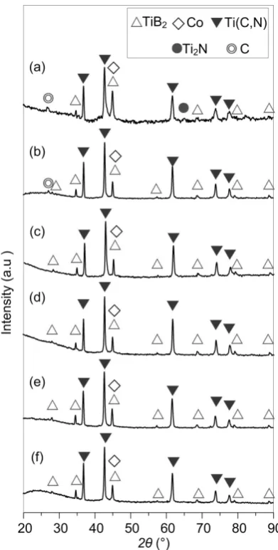
As seen in the XRD patterns in Fig. 1, the sintering tem-perature significantly influences the phase composition of Ti(C,N)-based cermets produced by RHP. When the sintering temperature was 1000 C, small amounts of graphite and Ti2N
were observed in addition to Co, TiB2 and Ti(C,N) phases
(Fig. 1(a)). As the temperature was increased to 1050 C, the C content decreased and the Ti2N phase disappeared entirely
(Fig. 1(b)). In the temperature range of 1100–1250 C, only the desired phases of Co, TiB2 and Ti(C,N) were identified by
XRD (Fig. 1(c)–(f)), without any intermediate compounds. In a previous article exploring the formation mechanism of Ti(C,N)-TiB2-Co cermets from the Co-Ti-C-BN system by
DSC,10) it was found that Ti-N compounds are initially
formed. With increasing temperature, the diffraction peaks of TiN shifted to a lower angle and the amount of carbon gradu-ally decreased. This could be explained by the difference in atomic radii (i.e., carbon has a radius of 0.91 Å, whereas ni-trogen is 0.75 Å), which means that the substitution of nitro-gen by carbon will lead to an increase in cell size. This ex-plains the shift in the TiN peaks to a lower angle, and so it is
[image:2.595.327.523.373.760.2]believed that Ti(C,N) is synthesized through the solid solu-tion of C into TiN. Indeed, Zhan et al.7) have produced
Ti(C,N) and TiB2 particles by combustion synthesis, and their
investigation of the reaction mechanism in the Ti-C-BN sys-tem produced similar results. Elevated sys-temperatures will ob-viously contribute to atomic diffusion and the solid solution of C into TiN, which would be why TiN and residual carbon disappear when the sintering temperature exceeds 1100 C (Fig. 1(c)–(f)).
It should be noted here that although oxygen and zirconia were not identified by XRD or EDS (Fig. 3(g) and 3(h)), their presence in the raw materials and zirconia balls could con-taminate the mixed powders. The absence of Zr in this case may be due to its high hardness and the low rotation rate (100 rpm) used during the milling process. As oxygen gener-ally exists on the surface of powder particles, high sintering temperatures and long holding times are required when cer-mets are produced by vacuum sintering. It is, however, also known that TiC particles can be prepared by the carbothermal reduction of TiO2 with C, wherein oxygen on the surface of Ti
particles is eliminated by the reaction: TiO2 + C → TiC + CO2.
As reactive hot pressing combines combustion synthesis and densification, it is assumed that any tiny amounts of oxygen on the surface of the raw material particles is eliminated by a chemical reaction between powders during the RHP process.
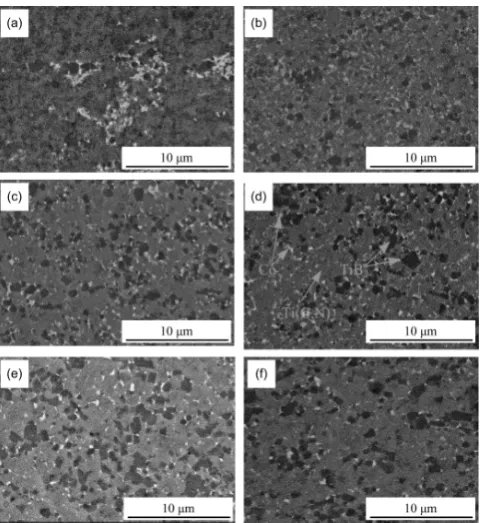
The SEM images in Fig. 2 show the products obtained by RHP at different sintering temperatures. As indicated, the white phase is Co; the black, irregular particles are TiB2; and
the grey matrix is Ti(C,N) ceramic. With a sintering tempera-ture of 1050–1250 C, Co and TiB2 were uniformly
distribut-ed in the Ti(C,N) matrix and TiB2 grains gradually grew
(Figs. 2(b)–(f)). Interestingly, Co is distributed in separate regions in Fig. 2(a), which suggests an inhomogeneous mix-ture. The Co content in the RHP sample sintered at 1250 C
also decreased to some extent (Fig. 2(f)), the reason for which may be that part of the Co in the Ti(C,N)-based cermets was squeezed from the graphite mold.
To further understand the effect of sintering temperature on the Ti(C,N) matrix, the fracture surfaces of the reacted sam-ples were observed. Note that for any given volume, spherical particles create the least amount of interfacial free energy, but cannot fully fill the whole space. This leads to a gap in the matrix, while the interfacial tension produced by the curved surfaces of the spheres brings about movement of the inter-face. It is for this reason that the Ti(C,N) particles often ex-hibited a polyhedral morphology,10,14) as shown by the EDS
results in Fig. 3(h). When the sintering temperature was raised from 1000 to 1250 C, the particle size of Ti(C,N) in-creased from 0.2 to 1 μm because grain growth is an exponen-tial function of temperature. With a further increase in sinter-ing temperature beyond 1200 C, nanometer-sized pores were observed on the surface of the Ti(C,N) grains (Fig. 3(e) and 3(f)). According to the literature15), these pores are mainly
caused by the decomposition of Ti(C,N) and volatilization of N2.
3.2 Relative density and mechanical properties
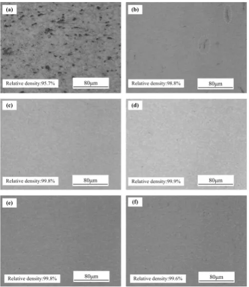
The metallographic pictures and corresponding relative densities of the cermets in Fig. 4 show that with increasing temperature, the relative density first increases, and then de-creases. The relative densities of the cermets sintered at 1000 and 1050 C were 95.7 and 98.8%, respectively; the lower val-ue of the former clearly resulting from the existence of black pores (Fig. 4(a) and 4(b)). According to the XRD patterns in Fig. 3 SEM images and EDS spectra of the fracture surfaces of cermets sintered at (a) 1000, (b) 1050, (c) 1100, (d) 1150, (e) 1200 and (f) 1250 C. Fig. 2 SEM images of polished surfaces of cermets sintered at (a) 1000, (b)
[image:3.595.49.290.68.330.2] [image:3.595.305.546.71.381.2]Fig. 1(a) and 1(b), a certain amount of graphite phase re-mained in these two cermets, which would explain the de-crease in relative density.10) In the case of the samples
sin-tered at 1100 and 1150 C, the relative density exceeded 99% and no pores could be observed (Fig. 4(c) and 4(d)). The XRD patterns (Fig. 1(c) and 1(d)) also indicated that the graphite phase had completely disappeared in these cermets. This offers further evidence that residual graphite is responsi-ble for the appearance of pores. When the sintering tempera-ture was increased to 1200 and 1250 C, a small quantity of nanometer-sized pores appeared on the surface of the Ti(C,N) particles, and their relative densities decreased to some extent (Fig. 4(e) and 4(f)). It would therefore seem that these nano-meter-sized pores (Fig. 3(e) and 3(f)) are the result of an ex-cessive sintering temperature causing decomposition of Ti(C,N). Note that the sintering temperatures used in this work were much lower than those in other studies (1650, 1850 and 1700 C).5,16,17)
Figure 5 shows the Vickers hardness of the cermets sin-tered at different temperatures, from which it can be seen that the Ti(C,N)-TiB2-Co composite cermets were harder than the
monophase Ti(C,N) cermet (1400–1800 HV10). The main reason for this is the formation of ultra-hard TiB2 in the
com-posite cermets, which increases their overall hardness. With an increase in sintering temperature from 1000 to 1250 C, the hardness of the Ti(C,N)-based cermets first increased and then decreased. Thus, it is the specimens sintered at 1150 C that exhibit a maximum hardness of 1947 HV10. The reasons for this change in hardness are as follows: firstly, the speci-mens sintered at 1150 C have a relatively higher density than the other specimens, which would tend to increase their hard-ness; secondly, the particle size of Ti(C,N)-TiB2-Co is
small-er than that of csmall-ermets sintsmall-ered at elevated tempsmall-eratures (e.g.
1250 C), and this grain refinement could simultaneously en-hance both the hardness and fracture toughness.
Figure 5 shows the fracture toughness of cermets sintered at different temperatures, in which we see that the fracture toughness exhibited the same trend as the variation of hard-ness, reaching a maximum of about 6.6 MPa·m1/2 at 1150 C.
The relatively lower fracture toughness mainly originated from the lower Co binder content (< 7 mass%) and the inher-ent brittleness of Ti(C,N) ceramic. This is comparable with other studies5,16), in which the fracture toughness values of
Ti(C,N)-TiB2-Ni cermets were only 7.07 and 4 MPa·m1/2. In
order to improve this fracture toughness, future work will need to focus on exploring the effect of Co content on the microstructure and mechanical properties.
The SEM micrographs in Fig. 6 show crack propagation in Ti(C,N)-based cermets prepared at sintering temperatures of 1150 and 1200 C. It is evident from this that intergranular fracture and transgranular fracture exist in both samples, but that cracks spread along the grain boundary with more deflec-tion in the cermet sintered at 1150 C (see Fig. 6(a)). In the cermet sintered 1200 C, the cracks cross through bigger TiB2
grains along a relatively straight path (see Fig. 6(b)). The greater toughness of the cermet sintered at 1150 C can there-fore be attributed to its smaller grains and strong interfacial bonding strength between grains, which helps to consume much of the energy needed for crack expansion through the mechanisms of intergranular fracture and crack deflection.
As the cermet sintered at 1150 C exhibited the most prefer-able combination of hardness and fracture toughness, its wear resistance was subsequently measured under dry sliding con-ditions. Meanwhile, comparative tests were carried out on P10 cemented carbide (hardness: 1620 HV10). As shown in Fig. 7, The groove depths in Ti(C,N)-based cermets and P10 were about 0.6 µm and 1.5 µm, respectively, which implies Fig. 4 Relative density and metallographic pictures of cermets sintered at
(a) 1000, (b) 1050, (c) 1100, (d) 1150, (e) 1200 and (f) 1250 C.
Fig. 5 Hardness and fracture toughness of cermets sintered at (a) 1000, (b) 1050, (c) 1100, (d) 1150, (e) 1200 and (f) 1250 C.
[image:4.595.326.527.67.198.2] [image:4.595.48.291.69.349.2] [image:4.595.311.543.249.329.2]that the wear resistance of Ti(C,N)-TiB2-Co is superior. The
morphology and EDS spectra of the worn surfaces of each sample (Fig. 8) reveal that thermal fatigue cracks and delam-ination occurred on the surface of P10, with these being caused by the continuous fraction and wear during the recip-rocating sliding movements of a cemented carbide ball.10) In
contrast, very few cracks or layer-stripping phenomenon were observed on the worn surface of the Ti(C,N)-based cer-met, thus further proving its higher wear resistance. One of the reasons for this is the higher hardness of Ti(C,N)-based cermet (1947 HV10). The large amount of oxygen detected on its surface by EDS (Spectrum 1) suggests that the high temperatures caused by frictional heat cause oxidation of its surface. Yazdi18) explored the wear behavior of pure Ti using
pin-on-disk testing, and found that titanium oxide is formed due to the high temperature at the interface. Investigation of the sliding wear behavior of TiCN-WC-Ni cermets by Ku-mar19) further argued that the dominant oxidation reactions of
TiC + (3/2)O2 → TiO2 + CO and TiN + O2 → TiO2 + (1/2)N2
occur during sliding tests because TiCN is a solid solution of TiC and TiN. Shobu et al.20) studied the frictional properties
of sintered Ti(CN)-TiB2 ceramics and the composition of the
frictional surface by electron probe microanalysis and elec-tron diffraction, which confirmed the existence of TiO2. It is
therefore reasonable to conclude that TiO2 was formed on the
worn surface of the Ti(C,N)-TiB2-Co cermets. It is plausible
that this presence of TiO2 could reduce the coefficient of
fric-tion, thereby improving the wear resistance of Ti(C,N)-based cermets.19,21,22)
4. Conclusions
(1) When a temperature of 1100–1250 C is used,
Ti(C,N)-TiB2-Co cermets produced through RHP technology are
de-void of intermediate compounds and have a uniform distribu-tion of Co and TiB2 in the Ti(C,N) matrix. The relative
densi-ty, hardness and fracture toughness first increase with sinter-ing temperature, and then decrease.
(2) RHP samples sintered at 1150 C displayed the most favorable overall properties in terms of their maximum rela-tive density and fine particle size. The hardness and fracture toughness were 1947 HV10 and 6.6 MPa·m1/2, respectively.
(3) Friction and wear tests revealed that Ti(C,N)-TiB2-Co
exhibits superior wear resistance to P10 cemented carbide due to its higher hardness and an oxide layer formed on its worn surface.This would help to improve the wear resistance of Ti(C,N)-based cermets cutting tools.
Acknowledgements
This work was supported by the Taizhou Science and Tech-nology Project (No. 15gy54), National Natural Science Foun-dation of China (No. 51005117 and No. 51404157), Funded By Open Research Program of Zhejiang Provincial Key Lab-oratory for Cutting Tools (No. ZD201501), and Public Proj-ects of Zhejiang Province (No. 2016C31049).
REFERENCES
1) D. Park and Y. Lee: J. Am. Ceram. Soc. 82 (1999) 3150–3154.
2) B. Basu, G. Raju and A. Suri: Int. Mater. Rev. 51 (2006) 352–374.
3) A. Bellosi, V. Medri and F. Monteverde: J. Am. Ceram. Soc. 84 (2001) 2669–2676.
4) L. Liu, C. Huang, B. Zou, X. Liang, H.L. Liu and H.T. Zhu: Adv. Mater. Res. 426 (2012) 155–158.
5) L. Wang, H. Liu, C. Huang, B. Zuo and X. Liu: Ceram. Int. 40 (2014) 16513–16519.
6) F. Yang, Z. Guo, J. Hao and Y. Shi: Adv. Mater. Res. 468–471 (2012) 1247–1250.
7) L. Zhan, P. Shen, S. Jin and Q. Jiang: J. Alloy. Compd. 480 (2009) 315–320.
8) M.X. Zhang, Y.Q. Huo, M. Huang, Y.H. Fang and G.P. Wang: J. Asian. Ceram. Soc. 3 (2015) 38–43.
9) M.X. Zhang, Y.Q. Huo, M. Huang, Y.H. Fang and B.L. Zou: J. Asian. Ceram. Soc. 3 (2015) 271–278.
10) X.R. Zhao, D.W. Zuo, M.X. Zhang, F. Xu and S.S. Feng: Int. J. Refract. Met. Hard Mater. 55 (2016) 1–10.
11) Z. Yang, Z. Liu, J. Ouyang, Y. Zhou, Y. Wang and W.G. Sloof: Int. J. Refract. Met. Hard Mater. 41 (2013) 54–59.
12) Y. Teng, S. Wang, Y. Huang and K. Zhang: J. Eur. Cera. Soc. 34 (2014) 985–990.
13) K. Niihara: J. Mater. Sci. Lett. 2 (1983) 221–223.
14) Y. Li, N. L, X. Zhang, C. Rong: J. Mater. Process. Tech. 206 (2008) 365–373.
15) J. Xiong, Y. Zhang, B. Shen, Y. He and J. Wang: P/M Technol. 21 (2003) 92–95.
16) G.J. Zhang: Ceram. Int. 21 (1995) 29–31.
17) H. Liu, Q. Shi, C. Huang, B. Zou, L. Xu and J. Wang: Chin. J. Mech. Eng. 28 (2015) 338–342.
18) R. Yazdi and S.F. Kashani-Bozorg: Mater. Chem. Phys. 152 (2015) 147–157.
19) B.V. Manoj Kumar and B. Basu: Int. J. Refract. Met. Hard Mater. 26 (2008) 504–513.
20) K. Shobu and T. Watanabe: J. Am. Ceram. Soc. 70 (1987) C-103–C-104.
21) K. Bonny, P.D. Bates, J. Vleugels, A. Salehi, B. Lauwers and W. Liu:
Wear 265 (2008) 1767–1775.
22) J. Meng, J. Lu, J. Wang and S. Yang: Mater. Sci. Eng. A 418 (2006) 68–76.
Fig. 7 Groove depths of cermet and P10.
[image:5.595.50.289.68.251.2] [image:5.595.49.290.285.342.2]