Interface Microstructure and Mechanical Properties of Dissimilar Friction
Stir Welded Joints between Zr
55Cu
30Ni
5Al
10Bulk Metallic Glass and Pure Al
Yufeng Sun
1, Hidetoshi Fujii
1,+1, Koichi Imagawa
1,+2, Yoshihiko Yokoyama
2,
Hisamichi Kimura
2and Akihisa Inoue
21Joining and Welding Research Institute, Osaka University, Ibaraki 567-0047, Japan 2Institute for Materials Research, Tohoku University, Sendai 980-8577, Japan
Dissimilar friction stir welding of Zr55Cu30Ni5Al10bulk metallic glass (BMG) to pure Al was carried out at different welding conditions.
Sound BMG/Al joints can be obtained at a rotation speed of 350 and 400 rpm. However, defects or crack may form in the stir zone when the rotation speed was either too low or too high. In the sound joints, a clear and straight BMG/Al interface was formed and no intermetallic compounds caused either by chemical reaction or crystallization from the amorphous phase can be detected within the entire stir zone. The hardness of Al side in the stir zone decreases with increasing of the rotation speed and is lower than that in the base material due to frictional heat input. The sound BMG/Al joints fractured in the heat affect zone of Al side and the tensile strength can reach about 91%of that of the base material. [doi:10.2320/matertrans.M2011376]
(Received December 6, 2011; Accepted February 27, 2012; Published April 18, 2012)
Keywords: friction stir welding, bulk metallic glass, stir zone, interface, crystallization
1. Introduction
Bulk metallic glasses (BMGs) have some unique proper-ties such as high strength, high hardness, and high corrosion resistance due to their disordered atomic structure. Recently, Wang1,2) summarized the physical and mechanical
proper-ties of almost all the BMG families. For example, the Zr-base BMGs show tensile strength larger than 2000 MPa and the Mg-base BMGs have a tensile strength larger than 900 MPa, which is much higher than that of their crystalline counterpart. From about one decade ago, the discovery of BMGs have been regarded to be the beginning of an era of new metallic materials and research studies in this area are still very active all over the world. Although some BMGs can be fabricated from the melt directly due to high glass forming ability, the size limitation is still a long-standing problem for BMGs to be used as structural materials. It is believed that the joining of BMGs or the joining of BMGs to crystalline materials may open a window to the application of BMGs. Recently, the welding feasibilities of BMGs by means of various welding methods have been investigated. For example, Wong3) and Shin4) successfully
produced friction welded joints of Zr-based BMGs rods and the amorphous structure can be retained. Wang et al.5,6)
systematically studied the microstructure evolution of laser welded Zr-based BMGs and found that the amorphous structure can be retained in the fusion welding zone due to the high cooling rate from the melt. However, the heat affect zone (HAZ) is sensitive area for the crystallization to take place. Kim and Kawamura et al.7,8) investigated the electron beam welding of Zr-based BMGs with crystalline Ni metal, and defect-free joints were achieved with bending strength higher than that of the crystalline metal. However, BMGs belong to non-equilibrium state alloys and have a potential of structural relaxation and crystallization.
Intermetallic compounds generally formed when BMGs are joined by fusion welding methods. Friction stir welding (FSW) was invented by TWI in 1991 to weld aluminum and aluminum alloys. As a solid state joining process, FSW requires much lower energy input than fusion welding and therefore high-quality products can be obtained with minimal distortion and oxidation, no solidification defects.9,10) With the successful application of FSW in the
aluminum industries, this technique has been significantly expanded to many other metallic materials, including other light alloys, such as Mg and Ti, and commonly used industrial alloys like those of Cu and Fe, carbon steel. Wang et al.11)first applied FSW to the joining of Zr-based BMGs to AlZnMgCu high strength Al alloys, which shows strong bonding and mixed microstructure with large BMG particles in the stir zone. Shortly after this first success, Ji et al.12) prepared Zr-based BMG joints without crystallization in the stir zone and Sun et al.13) fabricated dissimilar joints between Zr-based BMG and pure copper using FSW technique. Up to now, few publications have been reported about the joining of BMGs by means of FSW method and the effect of welding conditions on the feasibility of dissimilar welding of BMG to crystalline metal has not been investigated in detail.
In this study, dissimilar friction stir welding of Zr55Cu30Al10Ni5 BMG with pure Al (A1050-H24) were
performed at various welding conditions. The Zr55Cu30Al10
-Ni5BMG was developed by A. Inoueet al.,14)which shows
high glass forming ability and has a wide supercooled liquid region of 90 K. After welding, it was found that strong bonding between the BMG and Al can be obtained and the embedment of larger BMG particles in the Al matrix can be avoided under suitable welding conditions. In addition, the microstructural evolution in the Al side along the BMG/Al interface is quite different with that in the BMG/Cu FSW processed counterpart. The mechanism of the microstructure formation as well as the mechanical properties of the joints was deeply investigated.
+1Corresponding author, E-mail: fujii@jwri.osaka-u.ac.jp +2Graduate Student, Osaka University
2. Experimental Procedures
In this study, commercially pure Al (1050-H24) and Zr-based BMGs, which have a chemical composition of Zr55Cu30Ni5Al10 and is well known for its excellent glass
forming ability, were used for the dissimilar welding process. To produce BMG plates, the mixture of pure metals were first melted in an arc melting furnace and then cast into could mold in a high frequency induction melting furnace to form BMG plates with a dimension of 55©27©2 mm3.
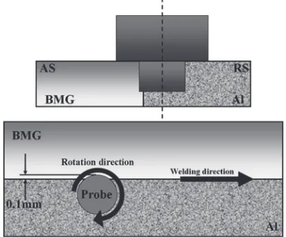
The welding processes were performed using a position-controlled FSW machine. As for FSW of BMGs, the use of position-controlled mode is supposed to be better than the load-controlled mode. When the welding temperature increase due to the frictional heat and begin to fall into the super-cooled liquid region of the BMGs, the strength of the BMGs will suddenly decrease to a very low value. This might cause the drop of the machine tool spindle and that may break the rotating tools easily, if the load-controlled mode were used. The rotating tool, which is made of WC-based material, has a 12 mm diameter shoulder with a 10° recessed shoulder surface, 4 mm diameter probe, and 2 mm long probe. The probe is the cylindrical-type and the tool was tilted by 3° during the welding process. In addition, the tool rotation speed was varied between 300 and 450 rpm to control the heat input and the traveling speed was fixed at 100 mm/min. Figure 1 shows the schematic illustration of the dissimilar welding process. During the welding process, the BMG plates were put on the advancing side and the pure Al plates on the retreating side. The tool probe was offset into the pure Al side with only 0.1 mm width of the probe in the BMG side. Otherwise, strong bonding between BMG and Al can not be obtained when the width of the probe into the BMG side is less than 0.1 mm. When the width of probe in the BMG side is larger than 0.1 mm, the welding process will become unstable and crystallization might happen due to the strong interaction between the hard rotating tool and the BMG plates. During welding, the temperature was measured by K-type thermocouple which was inserted at the interface of the two different plates.
After FSW, thermal stabilities of thin BMG plates cut close to the joint interface were measured by differential scanning calorimetry (DSC, Bruker, DSC 3300SA) at a heating rate of 20 K/min in a flowing Ar gas atmosphere. The phase constitution along the joint interface in the stir zone was examined by a Bruker D8 discover micro-area X-ray diffraction (XRD) system and microstructures of the dissim-ilar joint were observed by scanning electron microscope (SEM), transmission electron microscopy (TEM) and elec-tron backscattered diffraction (EBSD). The samples for the TEM observations were prepared using a focused ion beam (FIB) instrument (Hitachi, FB-2000S). The TEM observa-tions were carried out at 200 kV using a Hitachi H800T microscope. The Vickers micro-hardness were measured using a (Akashi, AAV 501) digital micro-hardness tester with the applied load of 100 gf (=0.98 N). The tensile tests were carried out with an INSTRON 5500R at a cross-head speed of 1 mm/min.
3. Results and Discussion
3.1 Macrostructure of the BMG/Al joints
After welding, the BMG/Al dissimilar welds show very similar surface appearance regardless of the different welding conditions. As a typical example, Fig. 2 shows the surface appearances of the dissimilar BMG/Al joints obtained at a rotation speed of 350 rpm. No obvious defects or superfluous flashes can be observed. Within the stir zone on the sample surface, a black line can be seen as indicated by an arrow, which indicated the interface between the BMG and Al plates. The black line was caused by the different thickness between Al and BMG plates in the stir zone after the welding process. Since BMGs are very hard materials, the tool wear is a key issue that should be considered. In this study, the rotating tools were mostly offset into the Al side and the strong friction between the BMGs and the rotating tools was avoided. As a result, the wear of the tools is not severe and can be neglected.
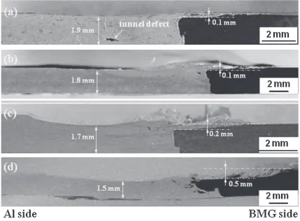
Figure 3 shows the macroscopic overview of the cross-section of the dissimilar joints welded at different welding conditions. The cross-sectional plane is perpendicular to the welding direction. When the rotation speed is as low as 300 rpm, tunnel defect as shown in Fig. 3(a) is formed in the Al side of stir zone due to the insufficient heat input. When
[image:2.595.312.541.71.221.2] [image:2.595.65.273.73.245.2]the rotation speed is between 350 and 400 rpm, no large defects or cracks are formed in the stir zone as shown in Figs. 3(b) and 3(c). It implies that sound dissimilar joints of BMG to Al can be obtained under suitable welding conditions. However, when the rotation speed increased to 450 rpm, the strong interaction between BMG and the rotating tool resulted in the embedment of some large BMG blocks in the Al side of stir zone, which is shown in Fig. 3(d). In addition, the thickness of the Al plate decreased greatly from 1.9 mm in the joint welded at 300 rpm to 1.5 mm at 450 rpm. Although position control mode was used during the welding process, more Al metals were extruded outside the stir zone to formflash due to the overwhelming softening of the materials at higher rotation speed. Accordingly, the thickness of the BMG plate also decreased with the increase of rotation speed. When the rotation speed is less than 400 rpm, the thickness reduction is about 0.1 to 0.2 mm. The thickness reduction only took place in the area below the shoulder of the tool, in which the temperature is the highest during the welding process. However, when the rotation speed is 450 rpm, the thickness of the BMG under the shoulder suddenly increase to about 0.5 mm and most of the broken BMG fragments were mixed into the Al side. In order tofill the gap caused by the collapse of the BMGs below the shoulder, some Al metals flew into the area above of the BMG plate.
3.2 Thermal stability of the BMG in the joints
Figure 4 shows the XRD curves measured at the BMG/ Al interface of the dissimilar joint obtained at different rotation speeds, inserted with the DSC curves of the BMG
base metals and the BMG/Al joints. As for the BMG/Al joints, the specimen for the DSC measurement were cut from the BMG side very close to the joint interface. Even though few small Al pieces may be mixed into the BMG specimen, it will not influence the detection of glass transition temperature (Tg) and crystallization temperature (Tx) of the amorphous
phase. According to the XRD curves for all the joints, some sharp Al diffraction peaks are imposed on a broadened diffraction peak, which is the typical feature of an amorphous structure. In addition, no diffraction peaks from intermetallic compounds can be observed in all the dissimilar BMG/Al
Fig. 3 Macrostructure of the cross-section of BMG/Al FSW joints obtained at (a) 300 rpm; (b) 350 rpm; (c) 400 rpm; and (d) 450 rpm.
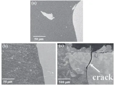
[image:3.595.84.513.71.387.2]when the rotation tools move close to the thermal couple and Figure 6 presents the SEM images showing the rather different interfacial microstructure of the dissimilar BMG/Al joints welded at varied welding conditions. When the rotation speed is 350 rpm as shown in Fig. 6(a), the interface between the BMG and pure Al plates is straight and clean. In the Al side close to the BMG/Al interface, a few blocky BMG fragments of a size of about 50 µm can be found distributed in the Al matrix, no Al fragments could be detected in the BMG side. Figure 6(b) shows the microstructure of the joint welded at 400 rpm, a great deal of small BMG particles distributed at the Al side along the BMG/Al interface. However, no blocky BMG fragment could be found in the Al side. Comparing the microstructure in Fig. 6(a) with that in Fig. 6(b), it is supposed that the joints welded at 350 rpm was deformed below or aroundTg, the BMG plate can still retain
its room temperature properties such as high strength and little global plasticity. The blocky BMG fragment is thus a result of wear debris caused by the strong friction between
Fig. 5 The thermal history measured for the dissimilar BMG/Al joint welded at 400 rpm.
[image:4.595.65.271.278.424.2] [image:4.595.109.487.481.762.2]the BMG surface and the tool shoulder. When the joint was welded at 400 rpm, the welding temperature fell into the supercooled liquid region of the BMG. The materials become quite soft and exhibit a viscoelastic property. Thus, the BMG plate can be greatly deformed and broke into small particles due to the strong stirring by the rotating tools. However, when the rotation speed increased to 450 rpm, the BMG was exposed at higher temperature near Tx. Even though the
BMG can still remain its amorphous structure, structural relaxation characterized by the reduction in free volume occurred during the welding process. The marked reduction in free volume decreased the propensity for shear band formation, the main mechanism of deformation in metallic glass, and hence promoted the brittle fracture at low stress.15,16) As a result, a large crack formed in the BMG
side as shown in Fig. 6(c).
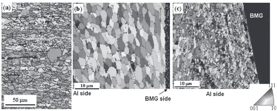
Figure 7 shows EBSD map of the cross-section of the dissimilar joints perpendicular to the welding direction. For comparison, the EBSD map of the base metal was also included. The base metal shown in Fig. 7(a) exhibits typical microstructure of cold rolled and then annealed Al, which consists of elongated grain structure and some newly nucleated grains due to static recrystallization. The average grain size of the base metal is about 7.0 µm. However, this typical microstructure completely disappeared after the welding process and can not be observed any more within the stir zone of the joints. Figure 7(b) shows the EBSD map of the microstructure of the BMG/Al joint interface welded at a rotation speed of 350 rpm. The black area indicates the BMG side, because no Kikuchi pattern can be detected due to its amorphous structure. Along the BMG/Al interface, elon-gated Al grains can be observed in the Al side, which might be formed by extrusion between the rotating probe and the hard BMG particles. In the area far from the BMG/Al interface, the stir zone has an equiaxial grain structure with an average grain size of about 4.8 µm, which is smaller than that of the base metal due to dynamic recrystallization. Figure 7(c) shows the EBSD map of the joint interface obtained at a rotation speed of 400 rpm. Similarly, the black area indicates the BMG side of the joints. It is interesting to find that the average grain size in Al side is about 1.1 µm and is much smaller than that in Fig. 7(b), which is against our
expectation. The Al grain size was supposed to be larger due to rapid grain growth, because much higher heat input is introduced into the joint when the rotation speed increased from 350 to 400 rpm. Further investigation of the Al microstructure reveals that some small black area can be found distributed separately in the Al side. The small black area might be caused by other phases, which will certainly retard the grain growth of the Al grains.17)
In order to further investigate the microstructure of the BMG/Al interface, TEM observations were carried out. Figures 8(a) and 8(b) show the TEM images of the micro-structure of the BMG/Al interface obtained at a rotation speed of 350 and 400 rpm, respectively. For both samples obtained at different welding condition, a clear and straight interface between two materials can be seen in the stir zone. No intermetallic compounds or reaction layer are formed in the entire stir zone at 350 rpm. However, some round black particles can be found distributed in the Al side along the welding interface at 400 rpm. From the corresponding diffraction pattern of the round particles inserted at the top left corner of Fig. 8(b), the round particles can be confirmed to have an amorphous structure. It also indicated that the small black area in the EBSD map in Fig. 7(c) was caused by the presence of BMG fragments.
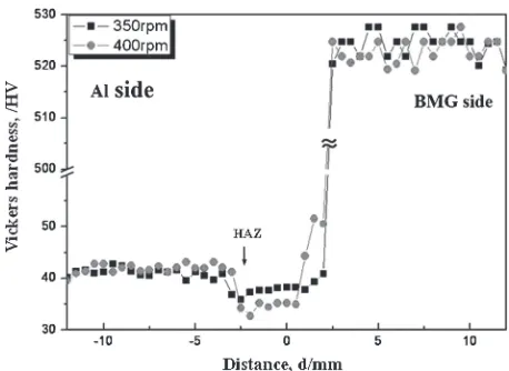
3.4 Characterization of the mechanical properties Figure 9 shows the hardness distribution along the center-line of the cross-section perpendicular to the welding direction of dissimilar joints. For both samples welded at 350 and 400 rpm, the hardness of the Al side in the stir zone was reduced in the stir zone. Since the base metal is half-hard commercially pure Al (1050-H24), the hardness of stir zone was reduced due to the annihilation of dislocations at high temperature during FSW process. In addition, hardness reduction is larger in the stir zone welded at 400 rpm than that at 350 rpm because of higher heat input. For both samples, the lowest hardness is located at the HAZ in the stir zone, as indicated by short arrow in Fig. 9. It is supposed that for the non-heat treatable Al alloy as in this study, the soft region with lower hardness can be produced because of the decrease in dislocation density in HAZ.18,19)However, for the
joint welded at 400 rpm, the hardness in the Al side close to
[image:5.595.69.522.67.249.2]the BMG/Al interface is higher than that at the same place of the joint welded at 350 rpm. According to the microstructure observation shown above, the higher hardness value is caused by the distribution of hard BMG fragments and the much smaller average grain size.
The tensile tests were also carried out for the BMG/Al joints and Table 1 summarized the ultimate tensile strength (·UTS), plastic elongation (¾) and welding efficiency of the
BMG/Al dissimilar joints obtained at different welding conditions, together with that of the base metal. The tensile tests for the joints welded at 300 rpm can not be performed, because the tensile specimens fractured at the tunnel defect suddenly at a very low applied load. For the specimen welded at 350 rpm, the tensile strength can reach about 125 MPa, which is about 91% of that of the base metal. The tensile
specimens fractured in the HAZ of the Al side, corresponding to the lowest hardness value within the entire stir zone. However, the tensile strength is very low when the rotation speed increased to 450 rpm. The fracture occurred at the BMG/Al interface, which can be seen from the appearance of the fractured specimen.
Figure 10 shows the appearance of the fractured specimen and the fractograph of the fractured specimen after tensile tests. The tensile specimen welded at 300 and 350 rpm both fracture in the Al side far from the BMG/Al interface as shown in Fig. 10(a), which reveals the strong bonding between BMG and Al plates. However, the tunnel defect formed in the specimen welded at 300 rpm caused an early failure of the materials at quite low applied force. The fractured surface exhibits typical dimple pattern in the joint welded at 350 rpm as shown in Fig. 10(b), which confirmed that fracture took place in the Al side and reveal ductile behavior. However, the joint welded at 450 rpm shows some smooth plane in some area on the fracture surface. Some blockly BMG fragments can also be observed and indicated by an arrow in Fig. 10(c).
The tensile tests reveal that the mechanical properties of the dissimilar BMG/Al joints can be affected by either the microstructure refinement or the embedded BMG fragments in the Al matrix. The microstructure refinement of Al in the stir zone is not expected to improve the mechanical properties. The annealing soft effect in the HAZ will decrease the tensile strength comparing with that of the pure Al base metal, which shows the same phenomena as that in the hardness tests. In addition, thefine BMG particles can only strengthen the materials close to the BMG/Al interface. On the contrary, the blocky BMG may fracture from the BMG plate and mix with Al in the stir zone if the rotation speed is too high. As a result, crack in the BMG block may form first and therefore deteriorate its mechanical properties.
4. Conclusions
The Zr55Cu30Al10Ni5 bulk metallic glass can be
success-fully joined to pure Al by friction stir welding. From the above description, the following conclusions can be drawn:
[image:6.595.89.508.69.247.2]Fig. 9 Hardness distribution along the cross-section of the BMG/Al joints.
Table 1 Tensile strength of the BMG/Al joints and the base metal.
·UTS ¾ Fracture location Welding Efficiency
Base Metal 137 MPa 5.4% ®
300 rpm ® ® Defect 0%
350 rpm 125 MPa 5.2% HAZ 91% 450 rpm 43 MPa 0.9% Interface 31%
[image:6.595.54.283.284.451.2] [image:6.595.46.291.510.576.2](1) Dissimilar BMG/Al joints can be successfully prepared by friction stir welding at a welding speed of 100 mm/min and a rotation speed varied from 350 to 400 rpm.
(2) The sound dissimilar joints show clean and straight BMG/Al interface. No imtermetallic compounds caused either by chemical reaction or crystallization from the amorphous phase can be detected within the stir zone. (3) The dissimilar BMG/Al joints exhibit lower hardness
value in the Al side in the stir zone than that of the base metal. The tensile strength of the dissimilar joints can reach about 91%of the pure Al counterpart. The tensile specimens fractured at HAZ of Al side in the stir zone, corresponding to the location with lowest hardness.
Acknowledgments
The authors wish to acknowledge thefinancial support by a Grant-in-Aid for the Cooperative Research Project of Nationwide Joint-Use Research Institutes on Development Base of Joining Technology for New Metallic Glasses and Inorganic Materials, Priority Assistance of the Formation of Worldwide Renowned Centers of Research-The Global COE Programs (Project: Center of Excellence for Advanced Structural and Functional Materials Design) from the Ministry of Education, Culture, Sports, Science and Tech-nology of Japan and Grant-in-Aid for Science Research from the Japan Society for the Promotion of Science.
REFERENCES
1) W. H. Wang, C. Dong and C. H. Shek:Mater. Sci. Eng. R44(2004) 4589.
2) W. H. Wang: Prog. Mater. Sci.57(2011) 437486. 3) C. H. Wong and C. H. Shek:Scr. Mater.49(2003) 393397.
4) H. S. Shin, Y. J. Jeong, H. Y. Choi, H. Kato and A. Inoue:J. Alloy. Compd.434(2007) 102105.
5) H. S. Wang, H. G. Chen, J. S. C. Jang and M. S. Chiou:Mater. Sci. Eng. A528(2010) 338341.
6) H. S. Wang, M. S. Chiou, H. G. Chen and J. S. C. Jang:Mater. Chem. Phys.129(2011) 547552.
7) J. Kim and Y. Kawamura:Scr. Mater.56(2007) 709712.
8) J. Kim and Y. Kawamura:J. Mater. Proc. Tech.203(2008) 112117.
9) R. Nandan, T. Debroy and H. K. K. H. Bhadeshia:Prog. Mater. Sci.53
(2008) 9801023.
10) Z. Y. Ma:Metall. Mater. Trans. A39(2008) 642658.
11) D. Wang, B. L. Xiao, Z. Y. Ma and H. F. Zhang:Scr. Mater.60(2009) 112115.
12) Y. S. Ji, H. Fujii, Y. F. Sun, M. Maeda, K. Nakata, H. Kimura, A. Inoue and K. Nogi:Mater. Trans.50(2009) 13001303.
13) Y. F. Sun, Y. Ji, H. Fujii, K. Nakata and K. Nogi:Mater. Sci. Eng. A
527(2010) 34273432.
14) A. Inoue and T. Zhang: Mater. Trans.37(1996) 185187. 15) A. Slipenyuk and J. Eckert:Scr. Mater.50(2004) 3944.
16) T. W. Wu and F. Spaepen:Philos. Mag. B61(1990) 739750.
17) Y. Morisada, H. Fujii, T. Nagaoka and M. Fukusumi:Mater. Sci. Eng. A433(2006) 5054.
18) H. J. Liu, F. Fujii, M. Maeda and K. Nogi:Sci. Tech. Weld. Join.8
(2003) 450454.
[image:7.595.84.513.82.341.2]19) Y. S. Sato, M. Urata, H. Kokawa, K. Ikeda and M. Enomoto: Scr. Mater.45(2001) 109113.