Effect of Microstructure on the Mechanical Behavior of Reactive Magnetron
Sputtered Al
2O
3/TiO
2Multilayer Ceramics
A. F. Dericioglu
1;21
National Institute for Materials Science, International Center for Young Scientist, Tsukuba 305-0047, Japan 2Department of Metallurgical and Materials Engineering, Middle East Technical University, 06531 Ankara, Turkey
Mechanical characteristics of reactive magnetron sputtered Al2O3–TiO2multilayer ceramics were studied. Tailored mechanical properties such as moderately high hardness and reasonable toughness were achieved through varying sputtering process parameters resulting in microstructural control at nano-scale. Interchanging Al2O3and TiO2layers with a single layer thickness of65{70nm were deposited on single crystal alumina (sapphire) substrates to form the multilayer structure composed of 10 layers. Deposition pressure was systematically changed throughout the process to obtain variety of microstructures. Nanostructured Al2O3 and TiO2 layers with a high degree of uniformity and interlayer bonding were obtained. The effect of the deposition pressure on the microstructure, and hence the ensuing physical characteristics of the multilayer ceramics were investigated. Resulting physical property sets were discussed in relation to the nanometer-order controlled microstructures. Potential of the nanostructured Al2O3–TiO2 multilayer ceramics for advanced engineering applications in terms of their processing and capacity for improved mechanical properties were addressed. [doi:10.2320/matertrans.MER2008055]
(Received February 15, 2008; Accepted August 11, 2008; Published October 3, 2008)
Keywords: ceramic multilayers, aluminum oxide, titanium oxide, sputter deposition, mechanical behavior, nanostructured multilayer films
1. Introduction
Multilayer ceramic materials have received considerable attention towards improving toughness of inherently brittle material systems through making use of their capability of deflecting growing cracks at weak interfaces.1)The potential of the approach of deflecting the crack at a weak interface before its passage to the adjacent layer was applied success-fully in various material systems.2–8) The aim of this approach is to prevent the catastrophic failure. In the case of brittle multilayers, as the deflecting cracks degrade transverse strength of the brittle multilayers, a new approach of using hybrid multilayers of homogeneous and heteroge-neous ceramics with strong interlayer bonding has been developed. In such systems communication of cracks growing in the homogeneous layers can be prevented by the heterogeneous layers.9–13)This approach is based on the potential of heterogeneous structures with thermal and/or elastic mismatches in allowing the operation of micro-scale fracture and crack-interface interaction events leading to crack propagation resistance.14,15)
Since the extent of the mechanical properties obtained from heterogeneous structures depends on the scale of the fracture events, scale-down the size of the micro-structural features to nanometer level is expected to lead to an inelastic deformation capability providing a more effective redistribution of stress intensities at the crack tip.16,17) In addition to this, rigorous design of the microstructural architecture of multilayer ceramics is another important aspect in developing proper materials for extreme operation conditions.18)In this respect, processing methods applied for the fabrication of multilayer ceramics and coatings have the greatest impact on the final properties through controlling their microstructural features mostly at nano-scale. For the processing of nanostructured ceramic coatings and hybrid multilayers with high mechanical characteristics various methods have been developed and applied. These comprise physical vapor deposition (PVD)19–23) and chemical vapor
deposition (CVD) including plasma modulated or assisted versions24–26)as well as thermal spraying techniques.27,28)
Previous studies have demonstrated that multilayer hybrid ceramics composed of layers with well matching physical properties and closely controlled microstructures have the potential of demonstrating unique mechanical property combinations. In the present work, multilayers of Al2O3 and TiO2, which were chosen because of their considerably matching thermal and elastic properties, were studied. Here, the focus was on the variation of the microstructural features of the presently investigated model multilayer material. Namely, size, anisotropy and spatial distribution of the nano-scale features of the Al2O3–TiO2 multilayer ceramics were controlled through the selected processing parameter which was the deposition (Argon) pressure. Consequently, the purpose of the present study is to show the effect of the deposition pressure (inert gas pressure) on the microstruc-tural features of the reactive magnetron sputtered Al2O3– TiO2multilayer ceramics and to investigate their mechanical properties as a function of the resulting microstructures.
2. Experimental Procedure
2.1 Processing and characterization
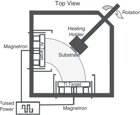
Al2O3 and TiO2 layers were deposited on single crystal Al2O3 (sapphire: A-plane) substrate by reactive magnetron sputtering process. The advanced sputtering equipment (MLC-200, Fraunhofer Institute Electron Beam and Plasma Technology, Dresden, Germany) (Fig. 1) employed in this study was capable of working in unipolar or bipolar modes under pulsed power that provides rapid suppression of the arcing, which allowed high deposition rates with sufficient stability. In the present study, bipolar mode was used for the deposition of the multilayer ceramics. The substrate was mounted on a holder where it rotated throughout the deposition process, and the temperature of the substrate was kept constant at 973 K to obtain crystalline phases. Three different deposition pressures (Ar pressure, denoted as PAr
hereafter) of 0.2, 0.5 and 1.7 Pa were used to change the resulting microstructure of deposited layers. Each individual layer was deposited for 5 min, and a total number of 10 layers were deposited for each Ar pressure.
Crystal structure of the deposited ceramic multilayers was determined by a thin film X-ray diffractometer (RINT 2500, Rigaku Corporation, Tokyo, Japan) using Cu-K
radiation. Microstructural observation of the multilayer ceramics was conducted by a field emission scanning electron microscope (SEM: S-4800, Hitachi High-Technol-ogies Corporation, Tokyo). Cross-sectional microstructures of the multilayer ceramics were used to determine the thickness of each layer and the resulting deposition rate for each phase.
2.2 Measurement of the mechanical properties
Mechanical properties of the multilayer ceramics were measured by micro-indentation tests using a conventional
depth-sensing microhardness tester (DUH-W201S,
Shimadzu Corporation, Kyoto, Japan) with a Berkovich type indenter. Young’s modulus, E, and hardness,H, were measured applying a maximum load of 30 mN. This maximum load was chosen to avoid formation of cracks and damage zone around the indentation sites. Young’s modulus was obtained from the unloading stiffness, S, of the multilayers calculated from the initial portion of the unloading curve of the indentation load versus depth data, which was fitted to the power law relation29)
P¼BðhhfÞm ð1Þ
wherePis the indentation load,his the indentation depth,B
andmare empirical fitting parameters, andhf is the residual depth of the indentation which was also determined by curve fitting. Unloading stiffness, S, is then derived by the differentiation of eq. (1) at the maximum depth of inden-tation. Young’s modulus,E, of the multilayer ceramics was obtained using the following relation assuming that the diamond indenter used in this study is perfectly rigid;
E¼ ð12Þð=AÞ1=2S=2 ð2Þ
whereis Poisson’s ratio of the multilayer ceramic andAis the projected area of the residual impression.
For the calculation of the hardness, residual impressions on the multilayer surface were observed by an atomic force microscope (AFM) (Dimension 3000 SPM, Digital Instru-ments, Inc., USA), and their projected areas were determined from the obtained error signal mapping that provided the highest possible image resolution. The nominal resolution of the measurement was 20nm. Hardness of the multilayer ceramics was then obtained through the ratio30)
H¼Pmax=A ð3Þ
in terms of the maximum applied indentation load,Pmax, and the projected area of the measured residual impression,A.
Indentation fracture toughness,Kc, of the multilayers was calculated using the relation31)
Kc¼ðE=HÞ1=2Pmax=c3=2 ð4Þ
wherecis the length of the radial cracks emanating from the corners of the residual impressions that was determined by SEM observations of the indented surfaces. Maximum applied indentation loads, Pmax, were 100 and 160 mN for this measurement. The constant in eq. (4) is an indenter geometry dependent empirical constant that was determined to be 0:024 for the Berkovich indenter using indentation experiments on monolithic sapphire (see Appendix).
Crack growth behavior of the multilayer ceramics was observed by indentation cracks grown on their polished transverse sections. The Berkovich type indenter was indented on the sapphire substrate side of the polished transverse section where the residual impression was several micrometers away from the multilayer/substrate interface. The path of the indentation crack that emanates from the apex of the residual impression on the sapphire substrate and penetrates into the multilayer ceramic was observed by SEM. In addition, four-point bending tests were conducted in ambient air at room temperature using a specially designed miniature rig mounted on a custom-made loading fixture with upper and lower span lengths of 8 and 16 mm, respectively. Employed specimens were rectangular prisms with dimensions of 20 by 1 by 1 mm, and a 110nm deep notch was introduced on the multilayer surface with the diamond probe of the previously mentioned AFM. The four-point bending test was conducted with a cross-head displacement rate of 0.5 mms1. Fracture surfaces of the four-point bend tested multilayer ceramics were examined by SEM.
3. Results
Figure 2 presents the X-ray diffraction patterns of the multilayer ceramics deposited at three different Ar pressures of 0.2, 0.5 and 1.7 Pa. For all deposition conditions deposited multilayers were fully crystalline and composed of a single Al2O3phase and two TiO2phases of anatase and rutile. From Fig. 2 it is evident that rutile phase formation was somewhat limited at 0.2 Pa of Ar pressure. Figure 3 shows the SEM micrographs of the polished transverse sections of the multilayer ceramics. TiO2 layers appear as the lighter phase in these micrographs deposited as the first layer on the
Rotation
Heating Holder
Substrate
Magnetron Pulsed
Power Magnetron
Ti Target
Al Target
Top View
[image:2.595.50.287.74.269.2]sapphire substrate, while the Al2O3 layers are darker in contrast which form the top layer of the multilayer. The interfaces between the layers become rougher towards the upper layers, and the roughness of the interfaces shows Ar pressure dependence. The average surface roughness (RMS) of the outermost layer of the multilayer ceramics obtained from AFM measurements are 3.8, 4.2 and 4.6 nm for the deposition pressures of 0.2, 0.5 and 1.7 Pa, respectively.
When the duty cycle (the ratio of the pulse-on time to the cycle time) and the deposition time were kept constant total thickness of the fabricated multilayer ceramics com-posed of 10 layers measured 650{700nm. Applied power limits were determined to produce almost equal TiO2 and
Al2O3 individual layer thicknesses of65{70nm in 5 min deposition time with a deposition rate of 13{14nm/min. As it is evident from Fig. 3, first TiO2 deposited on the sapphire substrate and the final Al2O3 layer that forms the outer surface are exceptions to this trend. The first TiO2 layer deposited on the polished substrate surface is
50% thinner compared to the others where the upper most Al2O3 layer deposited on the underlying rough multilayer
vice versa.
Microstructural examination of the polished cross-sections revealed the presence of elongated voids trapped between the columnar grains whose longitudinal axis is parallel to the deposition direction (Fig. 3). Because of their high aspect ratio these nanometer-order elongated voids are referred as ‘‘longitudinal-voids’’ (Lv) hereafter emphasizing their importance on the mechanical behavior of the multilayer ceramics. The amount of the longitudinal-voids was quanti-fied as longitudinal-void surface area per unit volume,SLv, from the cross-sectional micrographs using a stereological relationship32)
SLv¼2PLv ð5Þ
where PLv is the density of the intersection points that randomly distributed longitudinal-voids make with the test lines piercing the surface of the specimen. The total length of the test lines on the cross-sectional micrographs changes between 11.3 and 17.5mmat a magnification of11104and
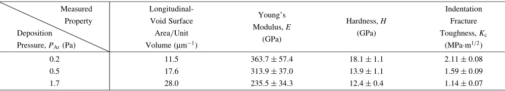
7104 times, respectively. The amount of longitudinal-voids given in Table 1 increases withPArwhere they reveal a fairly homogeneous distribution in the ceramic layers at all deposition pressures as observed in Fig. 3.
χ-Al2O3
TiO2(Anatase)
TiO2 (Rutile)
PAr= 0.2 Pa
PAr= 0.5 Pa
PAr= 1.7 Pa
20 40 60 80
2θ (Degrees)
Intensity (a.u.)
Fig. 2 Thin film X-ray diffraction patterns of the Al2O3–TiO2multilayer ceramics deposited at three different Ar pressures.
SLv: Longitudinal-Void Surface Area per Unit Volume (µm-1)
PAr: Deposition Pressure (Pa)
100 nm 100 nm 100 nm
PAr= 0.2 Pa PAr= 0.5 Pa PAr= 1.7 Pa
SLv= 11.5 µm-1 SLv= 17.6 µm-1 SLv= 28.0 µm-1
Substrate Substrate Substrate
Al2O3 TiO2
(a) (b) (c)
[image:3.595.50.288.71.232.2]Fig. 3 Polished cross-sections of the Al2O3–TiO2multilayer ceramics where longitudinal-voids trapped between the columnar grains can be observed.
Table 1 Measured longitudinal-void content, Young’s modulus, hardness and indentation fracture toughness of the multilayers for three different deposition pressures.
Measured
Longitudinal-Young’s Indentation
Property Void Surface
Modulus,E Hardness,H Fracture
Deposition Area/Unit
(GPa) (GPa) Toughness,Kc
Pressure,PAr(Pa) Volume (mm1) (MPam1=2)
0.2 11.5 363:757:4 18:11:1 2:110:08
0.5 17.6 313:937:0 13:91:1 1:590:09
[image:3.595.69.517.466.599.2] [image:3.595.48.548.692.782.2]For the measurement of the mechanical properties of the multilayers such as Young’s Modulus,E, hardness, H, and fracture toughness,Kc, indentation technique was employed. Since the mechanical properties of thin films are affected by the interfacial bonding to the substrate, applied indentation
depths should not exceed 10{20% of the total film
thickness in this type of measurements to prevent the perturbation caused by the substrate.33) Although this limitation secures the reliability of the measured mechanical properties by indentation techniques, acceptable results can also be obtained applying substantially greater indentation depths.34) In the case of multilayer films, however, the indentation depth should include a reasonable number of layers so that the measured data can represent the average mechanical property of the overall structure. Finally, while considering the balance between the two factors mentioned above, the maximum indentation loads should be chosen in a way that cracking, delamination or chipping free indents are generated for hardness and Young’s modulus ments whereas the indents for fracture toughness measure-ments should only contain radial through thickness cracks emanating from their corners.
In the present study, an optimum condition for Young’s modulus and hardness measurements of the multilayer ceramics without crack formation around the indentations was obtained applying 30 mN of maximum indentation load. Figure 4 shows indentation loading-unloading curves for three different multilayers at a maximum load of 30 mN, from which their Young’s moduli were obtained. From these curves it is clear that maximum penetration depth is
240{270nm which corresponds to 35% of the total multilayer thickness covering 3–4 upper layers of the multilayer ceramics. In an ongoing, parallel study on thicker multilayers fabricated under identical conditions, indentation experiments at varying loads, and hence various maximum indentation depths confirmed that selected relative penetra-tion depth is effective in revealing the average Young’s modulus and hardness values of the present multilayers free from the substrate effect (See Appendix). AFM surface mapping of the indented region in the multilayer ceramic
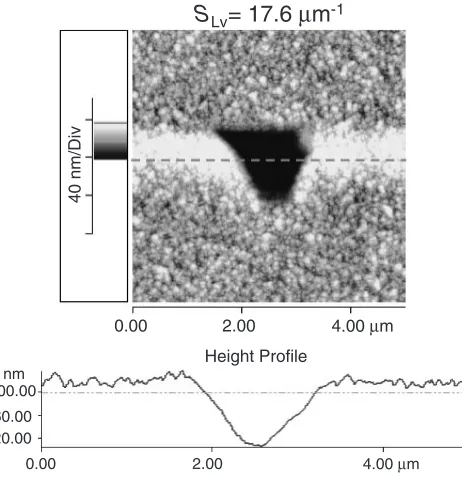
with the second highest elongated void content, SLv¼
17:6mm1, is depicted in Fig. 5. The height profile of the broken line drawn to the center of the indent reveals that the residual indentation depth is125nm, which is also repre-sentative for the indentations of the two other multilayers.
Table 1 shows Young’s moduli of the multilayers obtained from the indentation measurements. Although there is experimental scatter of about 50GPa in the measured
values, the maximum average Young’s modulus of
360GPa is obtained for the minimum amount of longi-tudinal-void content where it gradually decreases with increasing longitudinal-void density. Measured hardness values of the multilayer ceramics are also given in Table 1. The multilayer ceramic fabricated at a deposition pressure of 0.2 Pa that contains the lowest amount of void formation (SLv¼11:5mm1) reveals the highest hardness value that ranges from17to 19 GPa.
Figure 6 shows load versus penetration depth curves obtained during the indentation of the multilayer ceramics for the loading conditions applied to determine fracture toughness, Kc. For this measurement considerably higher maximum loads were applied compared to that of the Young’s modulus and hardness measurement. A maximum applied indentation load of 160 mN provided clear radial cracks which emanate from the corners of the indents on the multilayer ceramics fabricated under a deposition pressure of 0.2 and 0.5 Pa (Fig. 7). In the case of the last multilayer ceramic processed at the highest deposition pressure of 1.7 Pa, 160 mN of maximum load resulted in interfacial delamination and chipping, and therefore, the applied maximum indentation load was reduced to 100 mN to avoid multilayer damage around the indentation and to obtain fracture toughness, Kc. Indentation fracture toughness values of the three multilayer ceramics deposited under varying Ar pressures change between 2 and 1 MPam1=2 as presented in Table 1.
0.0 0.1 0.2 0.3 0.4 0.5
0 5 10 15 20 25
30 SLv= 11.5 µm
-1
S
Lv= 17.6 µm
-1
SLv= 28.0 µm-1
Load (mN)
Penetration Depth (µm)
Fig. 4 Load vs. penetration depth curves obtained during the indentation tests used for Young’s modulus and hardness measurements.
S
Lv= 17.6
µ
m
-140 nm/Div
0.00 2.00 4.00 µm
0.00 2.00 4.00 µm
20.00 60.00 100.00
nm
Height Profile
Fig. 5 AFM topographic image of the multilayer ceramic (SLv¼
[image:4.595.50.288.71.253.2] [image:4.595.312.543.74.314.2]4. Discussion
It was shown that the sputtered Al2O3/TiO2 multilayer ceramics are fully crystalline, and they are composed of columnar grains typical to sputtered ceramic films.35) This structure typical to sputtered ceramics was determined to contain longitudinal-voids distributed among the columnar grains whose amount increased with increasing deposition (Ar) pressure. The kinetic limitations of the deposition process accounts for the accumulation of voids along the columnar grain boundaries.36)In a former study, the increase in the amount of elongated voids with increasing deposition pressure in TiO2 layers deposited via reactive magnetron sputtering was attributed to the decreasing relative amount of the bombarding particles in the plasma forming a more porous final structure.37) Void content in the present multilayer ceramics also showed a similar dependence to deposition pressure as in the case of sputtered single phase TiO2 films.
Mechanical properties of the multilayer ceramics were determined using indentation technique as a function of the
longitudinal-void content. Although it is quite critical to eliminate the substrate effect from the measurements while including a representative number of individual layers in the indent to obtain average properties of the multilayers, a balance was obtained in the present study by varying the maximum applied loads. Measured Young’s modulus and hardness values of the Al2O3/TiO2 multilayers showed a decreasing tendency with increasing longitudinal-void density. For both of these properties this tendency seems to be reasonable as the material becomes more compliant and reveals lower load bearing capacity with increasing porosity.
Nevertheless, despite its porous structure the multilayer ceramic deposited at the lowest Ar pressure revealed Young’s modulus and hardness values which are higher than those of bulk TiO2 and comparable to those of bulk Al2O3. Specifically, measured hardness values of the deposited multilayers are comparable with the reported hardness values of some commonly used bulk engineering ceramics such as magnesium aluminate spinel (18.4 GPa), silicon nitride (21.6 GPa) and silicon carbide (21.8 GPa) measured using nanoindentation with Berkovich indenter.38) Although the hardness values obtained in the present multilayer ceramics are not as high as the hardness of nanostructured superhard materials exceeding 40 GPa level,39) they are similar or in some cases even higher than those of CVD or PVD processed metal nitride multilayer coatings of comparable thickness.8,23)
A similar difficulty in regard to the maximum penetration depth reached during the tests was also encountered in the case of indentation fracture toughness measurements. Max-imum indentation depths usually exceeded 70% of the total multilayer thickness, and in some cases, the depth almost reached the entire section of the multilayer ceramic (Fig. 6): suggesting the presence of the inevitable substrate influence on the film fracture process during fracture toughness measurement. However, a more important point here is that the approach used to determine the fracture toughness by indentation, which is mainly applied to bulk materials and predicted by eq. (4), is not always directly applicable to thin
(a)
1
µ
m
(b)
1
µ
m
S
Lv= 17.6
µ
m
-1c
c
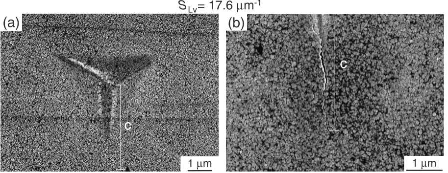
Fig. 7 (a) Residual indentation on the multilayer ceramic surface showing the radial cracks emanating from its corners and (b) close-up of the radial crack whose length was used for the indentation toughness estimation.
0.0 0.1 0.2 0.3 0.4 0.5 0.6 0.7 0.8 0.9 1.0 0
20 40 60 80 100 120 140 160
SLv= 11.5 µm-1
SLv= 17.6 µm-1
SLv= 28.0 µm-1
Load (mN)
Penetration Depth (µm)
[image:5.595.50.288.67.248.2] [image:5.595.71.528.581.758.2]films, since typically the cracks generated by indentation on the thin film surfaces tend to deviate from halfpenny shaped as assumed by the model.31)
In the present multilayer ceramics, anisotropic nature of the sputtered material caused by its typical microstructural features is also an important factor which may have affected the measured indentation toughness values. In addition to this, it should be mentioned that eq. (4) is applicable in the absence of residual stresses in thin films which may be present in the fabricated multilayers due to thermal expansion mismatch and/or growth process. Nevertheless, for hard coatings on harder and stiffer substrates as in the case of the current study, it may be reasonable to assume that the residual stress only modifies the crack shape.40) Con-sequently, in the present study, since the maximum applied indentation load that ranges between 100 and 160 mN and the 3/2 power of the crack length that changes between
3:5{6:5mmfollow a fairly linear relationship, eq. (4) was used to estimate the indentation fracture toughness of the multilayer ceramics,Kc, as an apparent value. As a result of the large maximum indentation depths and the mentioned limitation of the applied estimation, determined fracture toughness values are not absolute and reported here for a comparison purpose within the studied material system to show the effect of the processing parameter controlled microstructure on the fracture toughness of the multilayer ceramics. Despite the presence of a certain amount of scatter in the determined fracture toughness values given as a function of longitudinal-void density (Table 1), the decrease in the fracture toughness with increasing amount of longitudinal-voids is clearly evident. This can be attributed to the interconnecting nature of the longitudinal-voids as their density increases which contributes to the formation
of macro-cracks providing them easy growth paths in the multilayer ceramics.
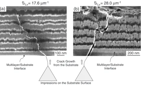
As the indentation fracture toughness of the sputtered multilayer ceramics showed porosity dependence, the interaction of an advancing crack with the microstructural features of the multilayer ceramics is of great importance. This interaction was observed by indentation cracks generated on the polished cross-sections of all three multilayers initiating from the substrate. Cracks emanating from the indents perpendicular to the multilayer/substrate interface penetrate from the sapphire substrate into the multilayer ceramics without causing any delamination at the interface (Fig. 8). Through the multilayer ceramics inden-tation cracks follow a zigzag pattern rather than a straight path without interlayer decohesion at Al2O3–TiO2 inter-faces. This observation points out that crack deflection mechanism could be achieved in the present multilayer material most probably because of the longitudinal-voids present in the structure (Fig. 8(a)). Figure 8(b) shows another example of the crack growth behavior in multilayer ceramics. In this case, crack branching is observed coupled with crack deflection in the TiO2 layer, where some part of the multilayer ceramic partially detaches from the rest of the system.
Fracture surfaces of the four-point bend tested single edge notched multilayers as well as the cracked sections around the large indentations both reveal clear evidences of the interaction between an advancing crack and the anisotropic microstructural features of the multilayers. Figure 9 shows the fracture surface of a four-point bend tested notched multilayer ceramic (notch depth is110nm). Rough fracture surface of the multilayer ceramic is clearly observed in contrast to the cleaved sapphire substrate suggesting the
200 nm
100 nm
Crack Growth from the Substrate
S
Lv= 17.6
µ
m
-1S
Lv
= 28.0
µ
m
-1Impressions on the Substrate Surface
(a)
(b)
Multilayer/Substrate Interface
Multilayer/Substrate Interface
[image:6.595.74.524.72.343.2]operation of crack deflection and branching processes during the growth of a primary crack under applied mode-I loading condition.
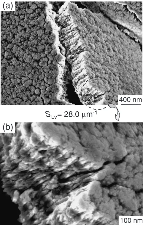
Figure 10 presents another example of crack growth behavior in multilayer ceramics. In this particular case the multilayer ceramic delaminates and spalls off in the vicinity of an indentation formed under a maximum applied load of 200 mN (SLv¼28:0mm1). The rough transverse fracture surface of the multilayer ceramic is clearly observable in Fig. 10(a). When the cracks that grow normal to the fracture surface of this spalled section are carefully observed (Fig. 10(b)), the interaction of the advancing crack with the longitudinal-voids in three dimensions is seen. This behavior suggests the occurrence of a series of micro-fracture events at the tip of a primary crack forming a three dimensional damage zone potentially redistributing the crack tip stress intensities.
As mentioned earlier, processing parameter controlled purpose-designed anisotropic microstructural features of multilayer ceramics composed of columnar grains housing fairly well-distributed longitudinal-voids play the key role in their mechanical behavior. Moderately high hardness values of the fabricated multilayer ceramics can be attributed to their fine crystallite size (column diameter) in nanometer range in accordance with Hall-Petch relation36) which is in competition with grain boundary sliding observed in mate-rials with grain sizes around 10–20 nm.41) In the extreme case, suppression of dislocation propagation by finer grains and grain boundary sliding by stronger grain boundaries is shown to be the key to obtain superhard materials.42)On the other hand, a balance between these two competing factors seems to result in moderately hard materials with reasonable deformability, and hence toughness. Observed crack growth behavior of the multilayer ceramics along with their hardness values evidently suggests that such kind of a balance is reached in the present system. Nevertheless, considering the longitudinal-void density dependence of indentation
toughness of present multilayer ceramics presented in Table 1, it can be concluded that the amount of void formation in the multilayer ceramics, and hence their distribution and resulting network structure should be optimized in order to maximize their toughening effect.
5. Conclusions
Multilayer ceramics composed of fully crystalline inter-changing Al2O3 and TiO2 layers with an individual layer thickness of 65{70nm were fabricated by reactive pulse magnetron sputtering. Microstructure of the multilayer ceramics composed of columnar grains with their longi-tudinal axes parallel to the deposition direction houses fairly well-distributed longitudinal-voids, whose amount can be controlled through changing deposition pressure, PAr, during the process. The interface between Al2O3 and TiO2 layers seems well-bonded without observable delamination. The multilayer ceramic processed under the lowest applied
PAr of 0.2 Pa resulted in the lowest longitudinal-void density with average Young’s modulus and hardness values
S
Lv= 17.6
µ
m
-1Substrate
500 nm
Fig. 9 Fracture surface of four-point bending tested multilayer ceramic showing the difference of its fracture behavior compared to that of the cleaved sapphire substrate.
S
Lv= 28.0
µ
m
-1(a)
(b)
[image:7.595.306.547.73.453.2]100 nm
400 nm
[image:7.595.49.289.75.278.2]of 360GPa and 18GPa, respectively. Measured relative indentation toughness of the multilayers follows a decreas-ing trend with increasdecreas-ing longitudinal-void density, which points out the requirement of keeping elongated voids isolated in the multilayer structure by controlling their content for improved toughening through optimizing proc-essing parameters.
Observation of the growth paths of the transverse indentation cracks as well as the fracture surfaces of the flexure-tested multilayers revealed the operation of crack deflection and branching processes at the longitudinal-void sites suggesting an overall toughening effect. Observed interaction of the advancing primary cracks with the longitudinal-voids of the structure forming a diffuse damage zone at the crack tip also revealed the potential of the fabricated multilayer ceramics to redistribute the stress concentrations. Finally, multilayer ceramics, which were shown to have the potential of revealing unique mechanical properties through their purpose-built anisotropic micro-structural features controlled by the applied processing parameters, deserve further consideration in order to explore and improve their mechanical characteristics.
Acknowledgements
The author acknowledges M. Kamei and Y. Tanaka from National Institute for Materials Science, Japan, and Y. Kagawa from the University of Tokyo, Japan, for their support on the experimental setup and for valuable discus-sions.
This work was partially financed by Special Coordination Funds for Promoting Science and Technology from the Ministry of Education, Culture, Sports, Science and Tech-nology of the Japanese Government.
Appendix
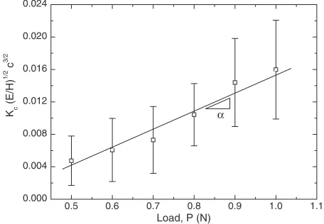
As already mentioned,in eq. (4) is an indenter geometry dependent empirical constant. Since Vickers or cube-corner type indenters are usually employed for the indentation toughness measurements, values of these geometries can frequently be found in the literature such as 0.016 and 0.036, respectively,38) which is not the case for the indenter geometry used in the present study. Therefore, the value of the constant for the Berkovich type indenter was obtained using indentation experiments on monolithic sapphire with well-known material properties. Incorporation of the Young’s modulus, hardness and fracture toughness of sapphire as 433.1 GPa, 25.9 GPa and 2.2 MPam1=2, respectively,38) into eq. (4) along with the experimentally determined radial crack lengths emanating from the inden-tations on the sapphire surface at various applied loads
revealed the empirical constant for the Berkovich
indenter. Figure A·1 shows the normalized crack length as a function of the applied indentation load where the slope of a linear fit to the presented data reveals the value of as
0:024. This is an intermediate value between the empirical constants of Vickers and cube-corner type indenters which are relatively blunter and sharper compared to Berkovich indenter, respectively.
Figure A·2 shows the hardness values of the 20 layered Al2O3–TiO2 multilayer ceramics, which were fabricated in the scope of an ongoing, parallel study under identical deposition conditions with those of the current report, as a function of maximum applied indentation load. The hardness values are seen to be decreasing with increasing indentation load, and hence indentation depth. As the hardness of the used sapphire substrate, which was measured to be 28– 30 GPa at maximum loads between 100 and 150 mN using the microhardness tester mentioned in the ‘‘Experimental Procedure’’ section, is higher than those of the multilayers fabricated in the current study, this decrease shows that the measured hardness values are free from the substrate effect. Following the initial decrease, which is most probably because of the measurement uncertainties due to small residual indentation typically encountered during indentation testing of ceramic materials, the hardness values reach to an almost constant value. Leveled off hardness values are comparable with those measured on 10 layered Al2O3–TiO2 multilayers presented in the current report revealing their average properties within the error margin.
0.5 0.6 0.7 0.8 0.9 1.0 1.1
0.000 0.004 0.008 0.012 0.016 0.020 0.024
Load, P (N) Kc
(E/H)
1/2
c
3/2
α
Fig. A1 Normalized radial crack length as a function of load applied by a Berkovich indenter.
0 20 40 60 80 100
0 5 10 15 20 25
30 PAr= 0.2 Pa
PAr= 0.5 Pa PAr= 1.7 Pa
Hardness, H (GPa)
Indentation Load, P (mN)
30-40% of the total
thickness
[image:8.595.312.540.75.233.2] [image:8.595.313.542.285.473.2]REFERENCES
1) J. Cook and J. E. Gordon: Proc. Royal Society of London Series a-Mathematical and Physical Sciences282(1964) pp. 508–520. 2) K. Kendall: Proc. Royal Society of London Series a-Mathematical
Physical and Engineering Sciences344(1975) pp. 287–302. 3) W. J. Clegg, K. Kendall, N. M. Alford, T. W. Button and J. D. Birchall:
Nature347(1990) 455–457.
4) A. J. Phillipps, W. J. Clegg and T. W. Clyne: Acta Metall. Et Mater.41 (1993) 805–817.
5) A. J. Phillipps, W. J. Clegg and T. W. Clyne: Acta Metall. Et Mater.41 (1993) 819–827.
6) C. A. Folsom, F. W. Zok and F. F. Lange: J. Am. Ceram. Soc.77(1994) 2081–2087.
7) C. A. Folsom, F. W. Zok and F. F. Lange: J. Am. Ceram. Soc.77(1994) 689–696.
8) P. Panjan, M. Cekada and B. Navinsek: Surf. Coat. Tech.174(2003) 55–62.
9) M. S. Dadkhah, D. B. Marshall, W. L. Morris and B. N. Cox: J. Am. Ceram. Soc.74(1991) 584–592.
10) D. B. Marshall: Am. Ceram. Soc. Bull.71(1992) 969–973. 11) P. E. D. Morgan and D. B. Marshall: J. Am. Ceram. Soc.78(1995)
2574–2574.
12) L. An, H. M. Chan, N. P. Padture and B. R. Lawn: J. Mater. Res.11 (1996) 204–210.
13) H. Y. Liu, B. R. Lawn and S. M. Hsu: J. Am. Ceram. Soc.79(1996) 1009–1014.
14) B. R. Lawn, N. P. Padture, H. D. Cai and F. Guiberteau: Science263 (1994) 1114–1116.
15) A. C. Fischercripps and B. R. Lawn: J. Am. Ceram. Soc.79(1996) 2609–2618.
16) A. G. Evans and F. W. Zok: The physics and mechanics of brittle matrix composites. Solid State Physics—Advances in Research and Applications, Vol. 47. Volume 47, Solid State Physics—Advances in Research and Applications; 1994. pp. 177–286.
17) A. G. Evans: Acta Mater.45(1997) 23–40.
18) J. Bai, K. Maute, S. R. Shah and R. Raj: J. Am. Ceram. Soc.90(2007) 170–176.
19) M. Larsson, M. Bromark, P. Hedenqvist and S. Hogmark: Surf. Coat.
Tech.91(1997) 43–49.
20) M. Berger, U. Wiklund, M. Eriksson, H. Engqvist and S. Jacobson: Surf. Coat. Tech.119(1999) 1138–1144.
21) P. E. Hovsepian, D. B. Lewis and W. D. Munz: Surf. Coat. Tech.133 (2000) 166–175.
22) P. H. Mayrhofer, F. Kunc, J. Musil and C. Mitterer: Thin Solid Films 415(2002) 151–159.
23) L. A. Dobrzanski, D. Pakula, A. Kriz, M. Sokovic and J. Kopac: J. Mater. Proc. Tech.175(2006) 179–185.
24) E. Bertran, G. Viera, E. Martinez, J. Esteve, Y. Maniette, J. Farjas and P. Roura: Thin Solid Films377(2000) 495–500.
25) C. Bjormander: Surf. Coat. Tech.201(2006) 4032–4036.
26) S. Veprek, M. G. J. Veprek-Heijman, P. Karvankova and J. Prochazka: Thin Solid Films476(2005) 1–29.
27) Y. Zeng, S. W. Lee, L. Gao and C. X. Ding: J. Eur. Ceram. Soc.22 (2002) 347–351.
28) R. S. Lima and B. R. Marple: J. Thermal Spray Tech. 16 (2007) 40–63.
29) W. C. Oliver and G. M. Pharr: J. Mater. Res.7(1992) 1564–1583. 30) F. R. Brotzen: Int. Mater. Rev.39(1994) 24–45.
31) B. R. Lawn, A. G. Evans and D. B. Marshall: J. Am. Ceram. Soc.63 (1980) 574–581.
32) K. J. Kurzydlowski and B. Ralph:The quantitative description of the microstructure of materials, (CRC Press Inc., Boca Raton, FL, 1995). 33) W. D. Nix: Metall. Trans. A20(1989) 2217–2245.
34) W. C. Oliver and C. J. Mchargue: Thin Solid Films 161 (1988) 117–122.
35) L. S. Donald:Thin-Film Deposition: Principles and Practice, (McGraw-Hill, New York, 1995).
36) N. B. Dahotre and S. Nayak: Surf. Coat. Tech.194(2005) 58–67. 37) P. Frach, K. Goedicke, C. Gottfried and H. Bartzsch: Surf. Coat. Tech.
142(2001) 628–634.
38) D. S. Harding, W. C. Oliver and G. M. Pharr: Thin Films: Stresses and Mechanical Properties V Symposium (1995) 663–668.
39) S. Veprek: J. Vac. Sci. Technol. A17(1999) 2401–2420. 40) J. Chen and S. J. Bull: Thin Solid Films494(2006) 1–7. 41) S. Veprek: Thin Solid Films317(1998) 449–454.