Preparation of Monosized Copper Micro Particles
by Pulsated Orifice Ejection Method
Kenta Takagi
1, Satoshi Masuda
1;*, Hiroaki Suzuki
2and Akira Kawasaki
1 1Department of Materials Processing, Graduate School of Engineering, Tohoku University, Sendai 980-8579, Japan
2Micro Powder Research Institute Inc., Aoba-ku, Sendai 980-0845, Japan
A pulsated orifice ejection method (POEM) has attained mass-production of monosized spherical micro particles of solder. In this method, the micro droplet melts are emitted from a small orifice by applying both mechanical pulses and constant gas pressure to the melt. This paper reports further development of this method for alternative monosized copper spherical particles with a size in the order of 100mm. The possibility of the droplet formation was strongly determined by the wettability of orifice material to the melt. Droplets of molten copper could be stably formed at a particularly high contact angle. Using an orifice with the low wettability, monosized copper particles are obtained in a wide range of process parameters such as the rod displacement and gas pressure. Their particle size was also clarified to vary with changes in the two parameters. Especially, the gas pressure may linearly control the particle size from 75 to 120mm, which is equivalent to 75 to 120% of the orifice diameter. All monosized particles produced by the POEM have an excellent mono-dispersivity less than 2.0 in standard deviation.
[doi:10.2320/matertrans.47.1380]
(Received February 8, 2006; Accepted March 14, 2006; Published May 15, 2006)
Keywords: pulsated orifice ejection method, monosized spherical particles, copper, size controllability
1. Introduction
Various micro-systems utilizing spherical micro particles have been proposed and industrialized in recent years. The representative example is micro-ball bonding assemblies in the semiconductor packaging such as the ball grid array, flip chip and so on.1) The design engineers on such a micro-system prefer a particle possessing higher properties than the conventional particles as typified by tin and solder particles. A copper particle has been particularly paid attention because of its electrical, thermal, mechanical and economical advan-tages. Actually, a copper-cored solder ball is adopted as a major candidate for the next generation of packaging technology.2,3) The implicit requirements for industrializa-tion of the copper spherical particle are its size variaindustrializa-tion, size controllability, size uniformity and mass-productivity. Since the demanded particle size is dependent on the latest particle array technique, the necessary size variation in future would be at least down to below 100mmin diameter. Poorness of size controllability and mass-productivity, essentially, re-stricts the application region, and the size uniformity influences a reliability of resultant micro-systems.
Several processes to produce monosized metal spherical particles have already been developed. The Rayleih atom-ization is an originative method to produce monosized metal spheres at an extremely high rate.4,5) In this method, a melt stream is being vibrated out of an orifice, and then the vibrated stream breaks up into monosized droplets according to Rayleih instability. However, there is no report that this method has accomplished monosized copper particles. Impulse atomization technique, which is an innovative approach based on the Rayleih atomization, has succeeded to mass-produce well mono-dispersed particles of copper besides low melting point metals.6)Even this method has not achieved monosized copper spheres with the size near
100mm. A plasma monosized droplet method would suc-cessfully satisfy with the above requirements.7) With this method, an extra-fine metal wire is prepared and precisely cut into bits with constant length. The metal bits are thrown into plasma flame for containerless melting, and spontaneously form into spherical droplets by their surface tension. There-fore, this method can possibly reduce the size of the particles as long as accurate size of metal bits can be prepared. At the present the method has realized particle size less than 100mm. One disadvantage for this method is its confinement to production employing a high multiple technique and large-scale facilities to accommodate the necessary processes for producing, precise cutting and plasma flame melting of the extrafine wire.
So far, we have developed a Pulsated Orifice Ejection Method (POEM) capable of mass-producing the monosized spherical micro particles and successfully prepared mono-sized solder particles of <100mmand size distribution less than 1% in standard deviation, at a high rate of 100 particles a second.8)In the POEM, repeating mechanical pulsations emit melt droplets out of an orifice to simply generate monosized particles without the need of careful optimization of process parameters to reduce and control the particle size. Further feature of our developed method is its capability to mass-produce monosized particles with only single process in a small area of several tens square meters. In this paper, we aimed at preparing monosized spherical copper particles by means of the POEM. However, the conventional POEM apparatus is not available for the copper particles, because copper is totally different from the tin alloy in melting point and melt properties such as surface tension and wettability. Hence, the POEM apparatus was firstly redesigned for the high melting point material. Subsequently, the feasibility study of the preparation of monosized copper particles and size controllability was conducted focusing on the demanded size near 100mm.
*Graduate Student, Tohoku University
2. Experimental Procedure
In the POEM, reciprocating action of cylinder-rod inter-mittently pushes the molten metal droplets with constant volume out of a small orifice which is equipped at the bottom of the tundish, as illustrated in Fig. 1(a). Gas pressure is also applied to the molten metal to assist the ejection of droplets. The molten droplets spontaneously form into a sphere by its surface tension and then solidify during falling. On the basis of simple fluid dynamics, we estimate that the ejection of molten droplets, which passes in extremely brief period, goes through the following phenomenon: firstly, the molten metal in the tundish is extruded by the downward motion of the rod as illustrated in Fig. 1(b-1). Once the rod is pulled up, the melt in the tundish flows upward such that a downward flow to the protrusion is prevented. The protrusion is elongated by the downward inertia against the surface tension. During the elongation, the moment the downward kinetic energy is consumed by the surface tension energy, the protrusion is pulled back into the tundish again. However, the protrusion with sufficient kinetic energy is able to keep extending against the surface tension and begins necking. A decrease in the circumference of the protrusion due to necking gradually attenuates the upward surface tension and the concave shape of the neck generates another surface tension that makes the protrusion spherical, as shown in Fig. 1(b-2). Consequently, the protrusion separates from the molten metal in the tudish and becomes a droplet as shown in Fig. 1(b-3).
The POEM apparatus was setup as indicated in Fig. 2. The ejection component shown in Fig. 1 was equipped onto the drop-tube and surrounded by a high frequency induction heater. The length of the drop-tube was about 1.5 m which is enough to solidify the molten copper droplet of submillimeter size. The crucible involving the tundish was made of graphite which is inert to molten copper and possesses the supply route with cross-sectional area of 1.8 mm2. An alumina
cylinder-rod was used considering high-temperature strength and high elastic modulus. The rod was reciprocated by piezoelectric actuator, which was driven by a voltage waveform from a function generator. Here, molten copper has notably higher surface tension compared to the molten solder in our previous research,8) such that larger kinetic energy is required according to our estimation in the prior paragraph. Thus, a driving system for the actuator was enhanced in order to elevate the velocity of the rod to more than twice the speed of its initial motion. The bottom of the tundish was sealed with a thin disc with a circular orifice of
100mm in diameter. The material for the orifice disc was anticipated to be the first key point in forming the copper particles of monosize because the contact angle between the molten copper and the orifice may influence the geometry of the protrusion. Therefore, we chose four candidate materials of 3 mol%Y2O3-ZrO2, Al2O3, SiC and graphite for the orifice
disc.
Raw material of 99.9% pure copper (Japan Pure Chemical Co. Ltd, Japan) was put into the tundish. Subsequently, the insides of the tundish and drop-tube were purged with 99.999% pure argon gas. The raw copper was then heated up to 1373 K. To eject droplets, the rod was moved in vertical motion at 10 Hz in frequency with one pulse composed of the downward velocity of4:7102m/s and the upward one of
3:5103m/s. Here, we predicted that the rod
displace-ment could possibly influence the droplet formation, its mono-dispersibility and furthermore, size controllability. Thus, the rod displacement was varied up to 7mm. Besides, for the same reasons the assisting gas pressure was also varied from 0 to 50 kPa. The detailed aspect of successive droplet ejection was filmed by a high-speed camera (MEMRECAM fx-K3, NACK Image Co. Ltd., Japan).
The particle size and its distribution for the obtained particles were determined by an image analyzer connected with an optical microscope. Morphological characterization of the particle was conducted by scanning electron microsco-py.
Measurement for the contact angle of molten copper with the materials that were used for the selected orifice was conducted using a high temperature contact angle measure-ment system (WET-1200, ULVAC-RIKO Inc., Japan) in order to discuss the relationship between the formation of droplets and wettability. These materials were machined into a thin plate with a thickness of 1–2 mm with one side of the plate polished using #1200 emery paper.
(a)
(b-1)
(b)
Cylinder-Rod
Supply Route
Tundish
Circular Orifice
Melt
Gas Pressure (b-2) (b-3)
Fig. 1 Formation of monosized particles on the pulsated orifice ejection method where (a) the reciprocating rod pushes constant amount of molten metal out from the small orifice, and (b) the sequential behavior of the melt near the orifice for the cyclic rod motion.
Induction heater
Piezoelectric actuator
Ar gas Ar gas
Cylinder-rod
Orifice
Droplet
Wave
Melt
High-speed Camera
[image:2.595.346.501.72.327.2] [image:2.595.50.293.74.155.2]3. Results and Discussion
The possibility of copper particle formation was first determined using the orifice discs of various materials. In the case where the contact angle between the molten copper and the orifice is below 90 degree, the droplet formation is readily predicted to be difficult because the melt immediately spreads on the bottom face of the orifice disc. All the contact angles for the chosen materials exceed 90 degree as indicated in Table 1. The orifice discs of silicon carbide and zirconia cannot form droplets at all, and the alumina orifice with the relatively high contact angle of 142 degrees did not readily form droplets for required enough time. Only the graphite orifice at the highest contact angle of 163 degrees stably formed copper droplets. It is therefore presumed that the orifice needs very high contact angle for formation of copper particles, and the minimum required angle lies between 142– 164 degrees. Our previous study demonstrated that the droplets of silicon can be ejected using the orifice which the contact angle to molten silicon is only 92 degrees.9) The differing results between copper and silicon were obviously attributed to the difference of their surface tension. Even if a high wettability allowed an increase in the surface tension due to an extension of the circumference of protrusion, the kinetic energy could overcome the lower surface tension of molten silicon. Thus, a material with a high surface tension like copper is difficult to form into particles employing the POEM. On the other hand, the POEM has potential to prepare particles of any materials by selecting an appropriate material for the orifice. This result also implies that an increase in the temperature of orifice destabilizes the particle formation because the contact angle generally decreases with increasing in temperature. Therefore, we conducted the preparation of copper particles at 1373 K which is right above the melting point of copper.
Meanwhile, only the wettability was not the determinant parameter for the formation of copper particles. Figure 3 shows the particle formation map using the graphite orifice with the diameter of 100mm and varying rod displacement and assisting gas pressure. When high gas pressure over 40– 50 kPa was applied into the tundish (the vertical line shaded region in Fig. 3), the melt stream spouted out of the orifice regardless of the rod motion. Under these conditions, the downward force in the protrusion must exceed the upward force by the surface tension at all time, otherwise the molten copper could not be ejected at the conditions of the blank region as shown in Fig. 3. The droplet formation was therefore observed under their intermediate conditions. The particle formation was then categorized into two; the
[image:3.595.325.524.75.230.2]dispersed particles and the mono-dispersed particles. Under the conditions within the dot shaded regions in Fig. 3, two or more droplets with different sizes were scatteredly ejected by a rod pulse. Thus, the resultant particles have size dispersion of some sorts as shown in Fig. 4(a). At the conditions indicated as the diagonally shaded regions, one droplet is observed to be ejected by one rod motion and fall at a
Table 1 Characteristics of the copper droplet formation using orifices made of different materials, and their corresponding wettability with molten copper determined by as values of their contact angles.
Orifice Material Contact Angel for
Molten Copper (1373 K) Droplet Formation
Zirconia (YSZ) 115 None
Silicon carbide (SiC) 135 None
Alumina (Al2O3) 142 Unstable
Graphite 163 Stable
Gas pressure,
P
/kPa
Rod displacement,
8
0 10 20 30 40 50
0 1 2 3 4 5 6
δ
/
µ
m
Fig. 3 Particle formation map with varying in the rod displacement and gas pressure. The diagonally shaded regions represent the conditions that are able to form monosized particles. The conditions in the dot shaded regions are able to form particles but their sizes are not uniform. Under the conditions in the vertical line shaded and blank regions, the melt is streamed and not ejected, respectively.
(a)
(b)
Fig. 4 SEM micrographs of the typical particles prepared under the conditions within (a) dot shaded region and (b) diagonally shaded region in Fig. 3. The particles (a) and (b) were obtained underd¼4:2mm
[image:3.595.47.293.105.179.2] [image:3.595.329.524.328.623.2]constant straight trajectory. The particles seen in Fig. 4(b) is an example for the particles obtained under such a condition, and have the average diameter of 110mm and narrow size distribution of 1.82 in standard deviation, which would satisfy mono-dispersibility for practical uses. The particles also have an excellent sphericity without significant rough-ness caused by grain boundary and landing unto the collector. In addition, there is no contamination from the atmosphere detected on their surface. As seen in the particle formation map of Fig. 3, such good monosized copper particles can be produced under relatively wide conditions.
Figure 5 shows the high-speed camera images of the droplet ejection under certain conditions for the monosized particles. The interval between the images and the shoot duration are 1 msec. The rod finished a pushing motion of at least for 150msec and immediately started moving up. Fig. 5(a) shows the image for the first 1 msec revealing the formation of copper melt into a columnar protrusion hanging inside the orifice and already had a neck near the exit of the orifice. Subsequently, the melt protrusion having the down-ward kinetic energy was segmented at the neck and flew out by itself. The zigzag form of the droplet just after emission is estimated to represent the liquid oscillation which was generated by a velocity differential in the droplet. Here, the droplet, which finally becomes a particle with similar size as the orifice diameter, seemed to become larger than the orifice diameter. This inconsistency was attributed to both the solidification shrinkage and the misimpression due to the residual image in the downward direction. Actually, the velocity of droplet in Fig. 5(d) is estimated to be about 2.1 m/s by comparing Figs. 5(c) and (d). Thus, this droplet with an apparent length of 330mm includes the residual image with 210mm. In consequence, the sequential images taken by the high-speed camera demonstrated that the prediction for ejection mechanism has substantial propriety. Controllability of particle size is the second requirement for industrialization and mass-production of the monosized particles. We investigated the variations of the particle size as a function of process parameters. According to the ejection
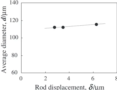
mechanism, net displacement of the rod and the assisting gas pressure would be important to control the particle size because these parameters can influence the size of the protrusion. For instance, the volume of detruded melt by the rod is obviously proportional to the rod displacement. Figure 6 shows the change of the average diameter of the monosized particles with varying rod displacement. Contrary to our prospect, the average diameter presents somewhat an increase as rod displacement increases. Here, the volumes of the droplet and the detruded melt by the rod motion are calculated using the particle size of 110mmand the displace-ment of 2.8mm to be 5:2104 and 7:9102mm3,
respectively. As a result, only 0.7% of the detruded melt was ejected out of the orifice as the droplet and the rest of detruded melt flowed up from the tundish to the crucible through the supply route. This fact implies that an increase in the rod displacement results in just an increase in the backflow melt. However, the rod displacement is effective in changing the diameter in the range of several micrometers.
Figure 7 shows the relationships between the average diameters of the monosized particles and the assisting gas pressure together with each standard deviation. The particle size is influenced by the gas pressure much more than the rod
(a)
100µm(b)
(c)
(d)
Fig. 5 High-speed camera images showing the ejection of a droplet under the condition for monosized particles. The interval between each images is 1 msec.
8
Rod displacement,
Average diameter,
d
/
µ
m
60 80 100 120 140
0 2 4 6
/
µ
m
δ
Fig. 6 The relationship between an average diameter of monoseized particles and rod displacement. All the particles were sampled under the gas pressure of 22.0 kPa in Fig. 3.
0 5 10 15 20 25 30
Standard deviation,
Gas pressure, P/kPa
Average diameter,
d
/
µ
m
40 60 80 100 120 140
20
(a) (b)
(c)
16
2 4 6 8 10 12 14
0
σ
/%
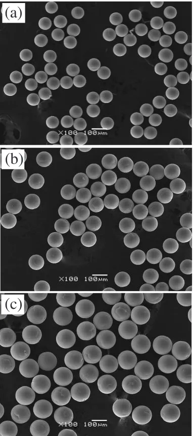
[image:4.595.329.524.75.226.2] [image:4.595.329.523.303.440.2]displacement. The increase in the gas pressure provides almost linear increase of diameter from 75mmup to 120mm. Figure 8 shows the scanning electron micrographs of the particles prepared by the gas pressure marked by (a)–(c) in Fig. 7. The images visually demonstrate that any crop of particles has high mono-dispersivity agreeing with the analyzed dispersion value indicated in Fig. 6. In addition, even though the particle size has changed, the geometrical features such as sphericity and surface smoothness are not lost. It is then presumed that the gas pressure is able to control the particle size in the range from 75 to 120% of the orifice diameter. The strong influence of gas pressure on the particle size may be contributed by some factors, especially, the backflow of melt. As mentioned above, most of the pushed melt by the rod flows back up to the crucible instead of being ejected from the orifice. In this situation, a downward gas pressure which was applied to the melt surface may suppress a rising melt level due to the upflow. This interpretation directly associates an increase in gas pressure with a decrease
in amount of upflowing melt and a resultant increase in the volume of the emitted melt from the orifice. Considering the largeness of the volume ratio of a droplet to backflow melt, the suppression of backflow is reasonably adopted as a cored mechanism of the size increased by the gas pressure. On the other hand, the gas pressure has an effect of pushing down an initial bottom level of melt in the orifice before starting a rod motion. The initial bottom level is more or less possible to influence the diameter of protrusion. For instance, if the bottom level drawn in Fig. 1(b-1) descended to the wall surface of orifice, the diameter should expand. Such a variation of the protrusion diameter may change a droplet size in consequence of changes in the surface tension and the volume of protrusion. Since such factors complicate on the effect of gas pressure, we have not theoretically clarified a quantitative relationship between the gas pressure and particle size yet. In order to prepare well-controlled size, clarification using fluid simulation technique is under way. In addition, the idea of influence of gas pressure on the initial bottom level may account for the complication of conditions for particle formation as seen in Fig. 3. For instance, the regions of the conditions of dispersed particles irregularly appear in the region for the monosized particles. If the surface tension and the volume of protrusion change as the gas pressure changes, the appropriate kinetic energy for monosized particles should change depending on the gas pressure. Therefore, the irregular presence of the condition of dispersed particles is presumed to be due to over- or under-displacement of the rod. Such a mechanism on particle formation will be refined with a numerical analysis as well as the investigation of size controllability.
4. Conclusion
We successfully mass-produced monosized spherical particles of copper using the pulsated orifice ejection method (POEM). Possibility of the melt droplet formation was primarily determined by the wettability of the ejection orifice to the melt. The copper droplets needed significantly high contact angles. Once the orifice material is decided, mono-sized copper particles are obtained under wide conditions of rod displacement and assisting gas pressure. The obtained monosized particles have a size of around 100mmas large as the diameter of the orifice, and an excellent mono-dispersiv-ity less than 2.0 in standard deviation. The mean particle size linearly increased with increasing either the rod displacement or the gas pressure. The gas pressure specifically was capable of linearly changing the particle size in the wide range from 75 to 120 percent of the orifice diameter. This size variability may be attributed mainly to the suppression of melt backflow by the gas pressure. The POEM is found to be a powerful tool for mass-production of monosized spherical particles of copper with good size controllability.
REFERENCES
1) R. R. Tummala:Fundamentals of Microsystems Packaging, (McGraw Hill, New York, 2001) pp. 492–493.
2) A. Ichida, Y. Yoshida, M. Mizukami and Y. Doi: Semiconductor package using micro balls and production method thereof, United States
(a)
(b)
(c)
[image:5.595.74.265.72.504.2]Patent No. 6, 518,667, Oct. 27th2000.
3) K. Uenishi, Y. Kohara, S. Sakatani, T. Saeki, K. F. Kobayashi and M. Yamamoto: Mat. Trans.43(2002) 1833–1839.
4) A. H. Lefebvre:Atomization and Sprays(Hemisphere, New York, 1989) pp. 29.
5) C. H. Passow, C.-A. Chun and T. Ando: Metall. Trans. A24A(1993) 1187–1193.
6) H. Henein: Mat. Sci. Eng.A326(2002) 92–100.
7) N. Chiwataet al.:Method of producing minute metal balls, United States
Patent No. 6, 911,618 June. 28th2005.
8) A. Kawasaki, Y. Kobarashi, K. Ichiki, Y. S. Kang and R. Watanabe: Proceeding of the 4thPacific Rim International Conference on Advanced
Materials and Processing (PRICM4), ed. by S. Hanada, (The Japan Institute of Metals, 2001) pp. 1131–1133.