Interaction between Substitutional and Interstitial Elements
in
iron Studied by First-principles Calculation
*Hideaki Sawada, Kazuto Kawakami and Masaaki Sugiyama
Advanced Technology Research Laboratories, Nippon Steel Corporation, Futtsu 293-8511, Japan
Interaction energies between substitutional 3d transition metal elements and an interstitial carbon atom iniron are estimated using the first-principles calculation. Calculated interaction energies are in good agreement with the experimental values reported for Co, Ni and Cu, showing a repulsive interaction experimentally. However, the interaction for such elements as Ti, V, Cr and Mn are also estimated to be repulsive, although the interaction between these elements and a carbon atom is known to be attractive experimentally. This apparent contradiction may be due to a difference in the formation energy of carbide precipitation from the atomic pair interaction energy.
(Received December 20, 2004; Accepted April 11, 2005; Published June 15, 2005)
Keywords: First-principles calculation, atomic pair interaction, precipitate, carbide,iron
1. Introduction
Interaction energy between substitutional and interstitial
elements in iron has been obtained by evaluation of the
solute C content after cementation or internal friction measurement. For example, Nishizawa determined the interaction energy between substitutional and interstitial elements from substitutional alloying element dependence on the experimentally obtained carbon content by the use of the relation between solubility of cementite and alloying element
content.1) Numakura et al. also determined the interaction
energy between substitutional and interstitial elements from the extra peak in the profile of the Sneak relaxation due to the
substitutional alloying elements.2)These experiments,
how-ever, include ambiguity given below. The internal friction measurement was employed to estimate the carbon content, although the substitutes change the proportionality constant used to evaluate the carbon content from the Sneak peak height. It is difficult to exclude the precipitate from the sample and the interaction energy must be estimated not only from the pair interaction but also from triangular, tetragonal, and higher interactions among the substitutional alloying element and the interstitial element in the sample. To remove the ambiguity from these experiments, further investigation of the atomic interaction energy is required. Furthermore, it becomes more important to evaluate the additive element dependence on the formation of the precipitate owing to less inclusion of carbon in steel, which also requires further investigation of the atomic interaction energy.
The first-principles calculation is used for subjects that are difficult to investigate experimentally. For example, the interaction energies between the substitutional alloying elements in some transition metals have been investigated
by the Korringa-Kohn-Rostoker (KKR) method.3)However,
the interaction energy between substitutional and interstitial elements has not been investigated so far, because the KKR method is less appropriate to treat an interstitial impurity with large deformation. On the other hand, the calculation method with the plane wave basis function becomes much more
useful owing to the ultrasoft pseudopotential4,5) or the
projector augmented plane wave method.6) In this paper,
the interaction energy between the substitutional and inter-stitial elements is investigated theoretically, and the behavior
of the substitutional and interstitial elements in iron is
discussed.
2. Calculational Details
In this study it is necessary to optimize the structure for a system that consists of 3d transition metal elements and a first row element. The pseudopotential method with Vanderbilt’s
ultrasoft pseudopotential7–10) is utilized for the efficient
structure optimization. The 3d and 4s states for the 3d transition metal elements and the 2s and 2p states for C are treated as valence states. The cutoff energies for the wave
function and the charge density are 4:5931017J (286.7
eV) and 8:8121017J (550.0 eV), respectively. The
ex-pression proposed by Perdewet al.is used for the generalized
gradient approximation functional of the exchange
correla-tion energy.11,12)
The interaction energyEbetween the substitutional and
interstitial elements is given as,
E¼E½Fen1MX þE½Fen E½FenX E½Fen1M;
where E is the total energy of the system, M is the
substitutional element, X is the interstitial element andn is
number of atoms in the unit cell without the interstitial atom.
The n must be sufficiently large to obtain the interaction
energy accurately, because the calculation uses the periodic boundary condition. Therefore, the lattice relaxation around
the C atom is examined for different unit cells, that is,n¼54
(333 conventional unit cells), n¼128 (444
conventional unit cells) andn¼250(555conventional
unit cells). In Table 1, the distances between the C atom and the first to fifth nearest neighbor Fe atoms are listed for the above mentioned three different unit cells. The distances between the ideal octahedral site and the first to fifth nearest
neighbor Fe atoms are also listed in the column of Fe54. The
first to fifth nearest neighbor Fe atoms from the C atom represented by X are shown in Fig. 1. As can be seen in Table 1, although the first nearest neighbor Fe atom goes *This Paper was Originally Published in J. Jpn. Inst. Metals68(2004)
977–982.
Special Issue on Computer Modeling of Materials and Processes
away from the C atom, the distances between the C atom and the second to fifth nearest neighbor Fe atoms change little. Furthermore, this feature is almost the same for the cases of
n¼54,n¼128 and n¼250. Therefore, the lattice relax-ation by the C atom does not significantly affect the position
of the atoms in the adjacent unit cell even for n¼54. The
lattice relaxation of Fe atoms around the Ti atom, which is substituted for the Fe atom, is shown in Table 2. Ti is chosen
as the substitutional atom because the Ti atom has the largest atomic radius in the 3d transition metal elements. The ideal
distances between Fe atoms are listed in the column of Fe54.
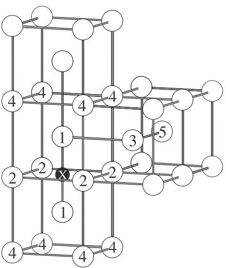
[image:2.595.46.549.94.194.2]The first to fifth nearest neighbor Fe atoms from the Ti atom (it is represented by M) are shown in Fig. 2. The first to fifth nearest neighbor interstitial sites from the substitutional atom M are also shown in this figure. In contrast to the relaxation of Table 1 Distance (in nm) between the C atom and the Fe atoms located at the 1st to 5th nearest neighbor sites from the C atom.
Brillouin-zone integrations have been performed on a grid of (abc)kpoints. The a, b and c are written as abc in the 2nd row.
Fe54 Fe54C Fe128C Fe250C
k-mesh 111 444 222 333 111 222
1st nn 0.143 0.175 0.177 0.178 0.178 0.178 0.178
2nd nn 0.202 0.198 0.198 0.198 0.198 0.199 0.198
3rd nn 0.320 0.321 0.321 0.321 0.321 0.322 0.322
4th nn 0.350 0.356 0.356 0.358 0.358 0.359 0.359
5th nn 0.429 0.428 0.428 0.428 0.428 0.429 0.429
1
2
2
1
4
X
5
2
3
4
2
4
4
4
4
4
4
[image:2.595.43.550.241.339.2]Fig. 1 1st to 5th nearest neighbor Fe atom sites from the interstitial atom (X).
Table 2 Distance (in nm) between the Ti atom and the Fe atoms located at the 1st to 5th nearest neighbor sites from the Ti atom. The number of grid points for the Brillouin-zone integrations are given in Table 1.
Fe54 Fe53Ti Fe127Ti Fe249Ti
k-mesh 111 444 222 333 111 222
1st nn 0.248 0.250 0.252 0.252 0.252 0.253 0.252
2nd nn 0.286 0.287 0.287 0.286 0.287 0.288 0.287
3rd nn 0.404 0.404 0.404 0.405 0.405 0.407 0.405
4th nn 0.474 0.474 0.474 0.474 0.475 0.476 0.475
5th nn 0.495 0.495 0.496 0.497 0.497 0.499 0.497
M
1
1
1
1
1
1
1
1
2
3
4
4
4
4
4
4
1
2
3
4
5
5
[image:2.595.53.285.364.639.2] [image:2.595.309.542.364.641.2]the first nearest neighbor Fe atoms around the interstitial C atom, there is little relaxation even for the first nearest neighbor Fe atoms from the substitutional Ti atom. In addition, we investigate the lattice relaxation for where both the substitutional atom and the interstitial atom are included in the unit cell. The distances between the substitutional Ti atom and the interstitial C atom are listed in Table 3. In this case the Ti atom is substituted for the first to fifth nearest neighbor Fe atom from the C atom. The calculated results also show that the distances between the Ti atom and the C atom depend very little on the size of the unit cell. Therefore,
the unit cell of n¼54 is sufficiently large to obtain an
accurate lattice relaxation around the substitutional Ti atom and the interstitial C atom.
The calculation is performed for a plural number of k
points, and the total energy and the charge density are
obtained from the wave functions of thekpoints. Tables 1, 2
and 3 show that the calculated lattice relaxation around the substitutional Ti atom and the interstitial C atom depends
very little on the number ofkpoints.
The unit cell size dependence and the number ofkpoints
dependence on the magnetic interaction and the interaction energy are also examined. These dependences on the magnetic moment of the Ti atom and the C atom are shown in Fig. 3. The C atom is located at the first to fifth nearest neighbor interstitial sites from the Ti atom as shown in Fig. 2. The cases that the Ti atom or the C atom exists in the unit cell are also calculated. The calculations are performed for 6 cases as shown in Fig. 3. The magnetic moments of the Ti
atom are almost the same except for the cases of n¼54,
k¼111andn¼128,k¼222. Only the
calcu-lations ofn¼54,k¼111andn¼250,k¼11
1 give different magnetic moments of the C atom from the
other cases. For the longer distance between the Ti and C atoms the magnetic moment of the Ti or C atom becomes closer to the magnetic moment where only the Ti or C atom exists in the unit cell. The magnetic interaction between the Ti atom and the C atom at the fifth nearest neighbor site is very small, because the magnetic moment of the Ti or C atom is almost the same as that where only the Ti or C atom exists in the unit cell. No significant error is obtained for the lattice relaxation, while the error of the magnetic moment is rather
large especially for the cases with smaller number ofkpoints.
For cases with a small number ofkpoints, the calculation is
performed using only the singular kpoints. The selected k
points affect directly the magnetic moment, giving the rather large error. On the other hand, the lattice relaxation is
indirectly affected by thekpoints; therefore, the error of the
lattice relaxation is not obvious. The influence of the band structure on the total energy is less direct than that on the
magnetic moment. The effect of the selectedkpoints on the
interaction energy is thought to be weaker than that on the magnetic moment, since the interaction energy is calculated by the total energies of four systems. The unit cell size
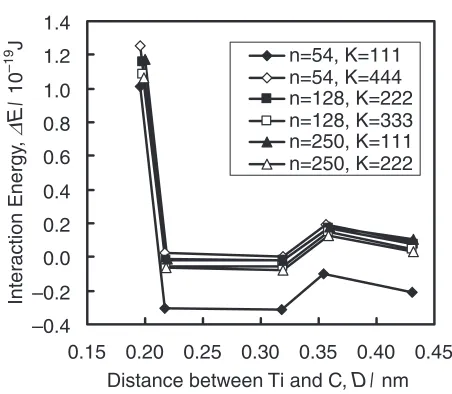
dependence and the number of kpoints dependence on the
interaction energy are shown in Fig. 4 and Table 4. The C atom is located at the first to fifth nearest neighbor interstitial sites from the Ti atom as shown in Fig. 2. The calculated total
energies are almost the same except for the case ofn¼54
[image:3.595.47.549.94.194.2]and k¼111. The differences between the total Table 3 Distance (in nm) between the C atom and the Ti atoms located at the 1st to 5th nearest neighbor sites from the C atom. The
number of grid points for the Brillouin-zone integrations are given in Table 1.
Fe54 Fe53TiC Fe127TiC Fe249TiC
k-mesh 111 444 222 333 111 222
1st nn 0.143 0.196 0.196 0.198 0.198 0.200 0.199
2nd nn 0.202 0.217 0.217 0.218 0.218 0.219 0.218
3rd nn 0.320 0.318 0.319 0.319 0.319 0.319 0.319
4th nn 0.350 0.354 0.356 0.358 0.358 0.359 0.359
5th nn 0.429 0.431 0.431 0.431 0.431 0.432 0.432
–0.9 –0.8 –0.7 –0.6
1st 2nd 3rd 4th 5th Ti
Magnetic Moment,
M
/
B
n=54, K=111 n=54, K=444 n=128, K=222 n=128, K=333 n=250, K=111 n=250, K=222
(a)
µ
–0.22 –0.20 –0.18 –0.16 –0.14 –0.12
1st 2nd 3rd 4th 5th C
Magnetic Moment,
M
/
µ
B
n=54, K=111 n=54, K=444 n=128, K=222 n=128, K=333 n=250, K=111 n=250, K=222
(b)
[image:3.595.311.543.213.576.2]energies ofn¼54,k¼444and those ofn¼250,k¼
222 are less than 0:21019J. All the
above-men-tioned calculations are performed for the experimentally obtained lattice constant of 0.286 nm. The calculated lattice
constant forn¼54andk¼444, namely, 0.285 nm is
accurate within less than 1%. The lattice constants are
optimized for Fe54, Fe54C, Fe53Ti and Fe53TiC (all the cases
of the first to fifth nearest neighbor) by the calculational
condition of k¼444, the errors between the
inter-action energies obtained for the experimental lattice con-stants and those for the calculated ones are less than
0:21019J. The changes of the lattice constants of n¼
54by the optimization should be larger than those ofn¼128
orn¼250, because the impurity content inn¼54is higher
than that inn¼128or n¼250. Therefore, the error of the
interaction energy for n¼128 or n¼250 owing to lattice
constant optimization is also less than0:21019J.
3. Interaction Energy between Substitutional and In-terstitial Elements inIron
In the previous section the interaction energy can be calculated within precision by the use of the unit cell of
n¼54 and the mesh of the reciprocal lattice points of
k¼444. The interaction energies between the sub-stitutional 3d transition metal elements and the interstitial C atom obtained by this calculational condition are presented in Fig. 5 and Table 5. The C atom is located at the first to fifth nearest neighbor interstitial sites from the substitutional 3d transition metal atom as shown in Fig. 2. The interaction energies of the first and second nearest neighbor sites are –0.4
–0.2 0.0 0.2 0.4 0.6 0.8 1.0 1.2 1.4
0.15 0.20 0.25 0.30 0.35 0.40 0.45
Distance between Ti and C, D/ nm
Inter
action Energy
,
∆
E
/
10
–19
J
n=54, K=111 n=54, K=444 n=128, K=222 n=128, K=333 n=250, K=111 n=250, K=222
[image:4.595.45.549.93.194.2]Fig. 4 Interaction energy between the Ti atom and the C atom for different unit cell sizes and number of grid points for the Brillouin-zone integrations.
Table 4 Interaction energy between the Ti atom and the C atom for different unit cell sizes and number of grid points for the Brillouin-zone integrations. Values are in1019J. The number of grid points for the Brillouin-zone integrations are given in Table 1.
Fe53TiC Fe127TiC Fe249TiC
k-mesh 111 444 222 333 111 222
1st nn 1.01 1.25 1.16 1.09 1.17 1.06
2nd nn 0:31 0.02 0:02 0:06 0:02 0:06
3rd nn 0:31 0.00 0:02 0:06 0:02 0:08
4th nn 0:10 0.20 0.17 0.15 0.18 0.13
5th nn 0:21 0.09 0.07 0.05 0.10 0.03
–0.2 0.0 0.2 0.4 0.6 0.8 1.0 1.2 1.4
Ti V Cr Mn Fe Co Ni Cu
Inter
action Energy
,
∆
E
/
10
–19
J
1st nn 2nd nn 3rd nn 4th nn 5th nn
[image:4.595.46.549.232.315.2]Fig. 5 Interaction energy between the substitutional 3d transition metal atom and the interstitial C atom.
Table 5 Interaction energy between the substitutional 3d transition metal atom and the interstitial C atom. Values are in1019J.
Ti V Cr Mn Co Ni Cu
1st nn 1.25 0.93 0.69 0.36 0.31 0.59 1.00
2nd nn 0.02 0.32 0.54 0.59 0.31 0.51 0.54
3rd nn 0.00 0.14 0.25 0.29 0.09 0.17 0.08
4th nn 0.20 0.17 0.19 0.21 0.05 0.13 0.09
[image:4.595.55.281.344.541.2] [image:4.595.314.542.344.537.2]various values for the 3d transition metal elements. Some 3d transition metal elements have considerable large positive interaction energies, that is to say, strong repulsive inter-action. On the other hand, the interaction energies of the third, fourth and fifth nearest neighbor sites differ little for the 3d transition metal elements, and are rather small, that is, less
than0:31019J. Therefore, the strong interaction between
the substitutional 3d transition elements and the C atom is obtained only for the first and second nearest neighbor sites. In Fig. 6 the distances between the substitutional 3d transition metal elements and the C atom are shown in order to investigate the origin of the 3d transition metal elements dependence on the interaction energies. In this figure the distances between the substitutional M atom and the C atom are normalized to those between the first to fifth nearest neighbor Fe sites and the C atom. Comparing Fig. 6 with Fig. 5, the 3d transition metal element dependence on the first nearest neighbor distance between the M atom and the C atom is similar to that on the first nearest neighbor interaction energy. Moreover, the first nearest neighbor distance between the M atom and the C atom is similar to the elemental dependence on the atomic radius. If the 3d transition metal
elements substituted in iron are connected by a covalent
bond with the surrounding Fe atoms, the bond distance may change dramatically with the number of electrons. The fact that the 3d transition metal element dependence on the interaction energy is similar to that on the atomic radius indicates that the 3d transition metal elements still have metallic electronic state. On the other hand, the 3d transition metal element dependence on the second nearest neighbor distance between the M atom and the C atom does not correlate with that on the interaction energy.
The magnetic moments of Fe atoms around the substitu-tional M atom are examined in order to understand the 3d transition metal element dependence on the interaction energy. Figure 7 shows the magnetic moments of the Fe atoms at the first to fifth nearest neighbor sites from the
substitutional M atom obtained by the calculation of Fe53M
withk¼444. The magnetic moment of the C atom at the interstitial octahedral site is supposed to be affected by the 2 first nearest Fe atoms. The 2 first nearest Fe atoms of the
C atoms located at the first to fifth nearest neighbor interstitial sites from the substitutional M atom are shown in Table 6 (see also Fig. 2). In Fig. 8 the magnetic moments of the 2 first nearest Fe atoms from the C atom are averaged by the use of –2.0
0.0 2.0 4.0 6.0 8.0 10.0 12.0
Ti V Cr Mn Fe Co Ni Cu
((M-C)–(F
e-C))/(F
e-C) (%)
1st nn 2nd nn 3rd nn 4th nn 5th nn
Fig. 6 Normalized distance between the substitutional 3d transition metal atom and the interstitial C atom.
2.2 2.3 2.4 2.5 2.6
Ti V Cr Mn Fe Co Ni Cu
Magnetic Moment,
M
/
µ
B
1st nn 2nd nn 3rd nn 4th nn 5th nn
[image:5.595.55.283.73.245.2]Fig. 7 Magnetic moment of the Fe atom located at the 1st to 5th nearest neighbor sites from the substitutional 3d transition metal atom.
Table 6 The position of the C atom from the substitutional 3d transition metal atom is shown in the first column. There are two Fe atoms next to the C atom, since the C atoms are located at the octahedral site. In the 2nd and 3rd column, the position of the two Fe atoms from the substitutional 3d transition metal atom is given.
C Fe
1 M 2
2 1 1
3 2 3
4 1 4
5 3 5
2.2 2.3 2.4 2.5 2.6
Ti V Cr Mn Fe Co Ni Cu
Magnetic Moment,
M
/
µB
2nd nn 3rd nn 4th nn 5th nn
[image:5.595.313.541.74.264.2] [image:5.595.308.545.362.681.2]Fig. 7. The substitutional atom dependence on the interaction energy is reproduced fairly well by that on the magnetic moment. Magnetic interaction is an important factor in understanding the 3d transition metal element dependence on the interaction energy.
It is impossible to decompose the experimentally obtained interaction energy into the interaction energies of the first to fifth nearest neighbor sites. Therefore, the calculated inter-action energies of the first to fifth nearest neighbor sites are averaged in order to compare the calculated interaction energies with the experimental ones. To find the average, the interaction energy is multiplied by the Boltzmann factor as,
X5
i¼1
"iziexpf"i=kBTg
X5
i¼1
ziexpf"i=kBTg
;
where"iis the interaction energy of thei-th nearest neighbor
site shown in Fig. 5 and Table 5, zi is the configuration
number, and the temperatureTis assumed to be 273 K. Thezi
are 6, 12, 24, 24 and 24 fori¼1, 2, 3, 4 and 5, respectively.
The averaged interaction energy is shown in Fig. 9, the interaction energies of Co, Ni and Cu are in good agreement
with the experimentally obtained values.1) The experiment
shows a rather strong attractive interaction between the C atom and the early 3d transition metal elements of Ti, V, Cr and Mn, while a weak repulsive interaction is obtained by the calculation. In other words, the calculated results disagree with the experimental results, where the attractive interaction is obtained experimentally. This suggests that the calculation does not take account of the phenomenon observed in the experiment. For example, microscopic clusters can be generated by the plural C atoms and 3d transition metal atoms. Although it is currently too expensive in terms of computational cost to consider a large number of cases of interaction energy among more than two atoms, this subject should be investigated in the near future. Another possibility
of the phenomenon unexpected in the calculation is that the substitutional element is accompanied with vacancies and interacts with the interstitial C atoms through the vacancies. In this case some interaction energies can be observed by the internal friction measurement, since the vacancy density strongly depends on the sample preparation and the plural C
atoms can be captured by one vacancy.13)
4. Stability of Carbides inIron
In the previous section it is shown that the calculated interaction energies disagree with the experimental ones for where the substitutional atom interacts attractively with the
interstitial atom. The stability of the carbides iniron has
already been investigated in detail experimentally. The stability of the carbide is examined to confirm the reliability of the calculational method and to discuss the relation between the atomic interaction and the stability of the carbide. The formation energy of the carbide MC from the C atom and the substitutional element M is obtained by,
E¼107=54E½Fe54 þ1=4
E½M4C4(NaCl type) E½Fe54C E½Fe53M:
The calculated values in the previous section are used for the
energies of Fe54, Fe54C and Fe53M. Although the only
carbide with the NaCl type crystal structure are TiC and VC, the crystal structure of the carbides is assumed to be the NaCl type in order to determine the 3d transition metal element dependence on the stability of the carbide systematically. The lattice parameters of the carbides are obtained by the calculation, because these are not known except for TiC and VC. The calculated lattice parameter of TiC is in good agreement with the experimentally obtained value within an error of 0.2%. Thus, it is appropriate that the calculated lattice parameter is used to obtain the total energy. The unit
cell of M4C4 is used for the calculation. The mesh of the
reciprocal lattice points of k¼888 is used after
confirming the convergence. The calculational conditions
of M4C4 are not same as those of Fe54, Fe54C and Fe53M
because of the different crystal system of MC fromiron.
The difference of the calculational condition may lower the accuracy of the calculated energy. Therefore, we refrain from quantitative discussion on the formation energy. The for-mation energy of TiC and VC is negative as shown in Fig. 10, which indicates that the C atom prefers precipitation of the carbides TiC or VC to a solid solution with a Ti or V atom. Since this calculation does not take account of the interface
energy betweeniron and carbide, it is impossible to discuss
the stability of the infinitesimal precipitate whose formation and interface energies are comparable. For a sufficiently large precipitate to avoid this problem, the calculated results indicate that the carbides of Ti and V are stable and those of
Co, Ni and Cu are unstable iniron. These calculated results
are consistent with the experimental ones. In addition, it indicates that the formation of the carbides is not equivalent to the attractive interaction between a pair of C atom and substitutional elements.
0.00 0.05 0.10 0.15 0.20
Ti V Cr Mn Fe Co Ni Cu
A
v
er
aged Inter
action Energy
,
∆
E
/
10
–19
J
[image:6.595.56.284.560.746.2]5. Activity Coefficient
The activity coefficient of C and 3d transition metal
elements iniron is calculated to confirm the reliability of
the calculational method. The solid solution energy of C and
3d transition metal elements iniron is calculated by,
E¼E½Fe54C E½Fe54 1=4E½C4(Graphite);
E¼E½Fe53M 53=54E½Fe54 E½M:
The activity coefficient of C and 3d transition metal elements
is obtained on the assumption that theE does not deviate
from that obtained in dilute solutions. The calculated values
in the previous section are used for the energies of Fe54,
Fe54C and Fe53M. The experimentally obtained most stable
crystal structures are used for the calculation of Graphite and M except for Mn. The calculation of Mn is performed for bcc structure of the same atomic volume through the experiment,
because the crystal structure ofMn consists of a large unit
cell with a complicated atomic position. The meshs of the
reciprocal lattice points of k¼12124 and k¼12
1212 are used for Graphite and M, respectively. The
calculated and experimental activity coefficients are listed in Table 7. The experimental activity coefficient of C is from Ref. 14, and those of the 3d transition metal elements are
estimated from the activity ofM¼0:0001mol% at
temper-atures of 1073 K calculated by the Thermocalc. The calculated values do not coincide with the experimental values. One of the reasons for the disagreement is that the different calculational conditions of Graphite and M from
those of Fe54, Fe54C and Fe53M may lower the accuracy. The
other reason is that the interface between Graphite (or M) and
iron cannot be taken into account in these calculations due
to the calculation time. However, the whole trend of the calculated activity coefficients has some resemblance to that of the experimental coefficients. The activity coefficients of C and Cu are calculated as being rather large values, because
the solid solution of these elements iniron is difficult. The
experimental activity coefficients of C and Cu are also larger than the other 3d transition metal elements. The calculated and experimental activity coefficients of Ti, V, Cr, Mn, Co and Ni are shown in Fig. 11. The calculated values have a similar trend to the experimental values except for Cr.
6. Summary
Previously, the formation energy of the transition metal
carbides iniron were considered related to the interaction
[image:7.595.48.547.105.148.2]energy between the transition metal element and the C atom. The interaction energies obtained by the first-principles calculation are in good agreement with the experimentally obtained values for Co, Ni and Cu which interact repulsively with the C atom in the experiment. On the other hand, the calculated and the experimentally obtained results are contradictory for the 3d transition metal elements of Ti, V, Cr and Mn, which have attractive interaction. One of the reasons for the contradiction is supposed to be that the plural transition metal atoms interact with the C atoms in the experiment. Another reason is that the transition metal atom interacts with the C atom through the vacancy. The calculated stability of the carbides agrees well with the experimentally obtained results. The explanation for these facts may be that the atomic interaction between the 3d transition metal M atom and the C atom becomes attractive only for a precipitate Table 7 Calculated activity coefficients and experimental values iniron at temperatures of 1073 K. Experimental activity coefficient of
C is from Ref. 14, and those of the 3d transition metal elements are estimated from the activity ofM¼0:0001mol% at temperatures of 1073 K calculated by means of the Thermocalc.
C Ti V Cr Mn Co Ni Cu
Calc. 549 0.0001 0.0001 0.0112 0.0186 0.0022 0.0596 239
Exp. 330 0.0200 0.1576 3.3461 1.3880 0.4073 1.4531 92
–3.0 –2.0 –1.0 0.0 1.0 2.0 3.0 4.0
Ti V Cr Mn Fe Co Ni Cu
F
o
rmation Energy of Carbide
,
∆
E
/
10
–19
J
0.38 0.39 0.40 0.41 0.42 0.43 0.44
Lattice Constant of Carbide
,
a
/
nm
M+C MC
[image:7.595.314.540.175.343.2]a
Fig. 10 Formation energy and lattice constant of 3d transition metal carbides.
0.00 0.01 0.02 0.03 0.04 0.05 0.06 0.07
Ti V Cr Mn Co Ni
γ
0 (Calc.)
0.0 0.5 1.0 1.5 2.0 2.5 3.0 3.5 4.0
γ
0 (Exp
.)
Calc. Exp.
[image:7.595.56.282.179.354.2]larger than a certain size even when the stable precipitate consists of the 3d transition metal element M and the C atom. In the future it is necessary to study the atomic interaction using an experimental technique to examine the atomic position, for example by applying a 3D atom probe.
REFERENCES
1) T. Nishizawa: Bull. Inst. Metals12(1973) 401.
2) H. Numakura, G. Yotsui and M. Koiwa: Acta Metall. Mater.43(1995) 705.
3) T. Hoshino, M. Asato and T. Mizuno: Meeting Abstracts of the Physical Society of Japan, vol.55, issue. 2 (2000) p. 853.
4) D. Vanderbilt: Phys. Rev. B41(1990) 7892.
5) K. Laasonen, A. Pasquarello, R. Car, C. Lee and D. Vanderbilt: Phys. Rev. B47(1993) 10142.
6) P. E. Blochl: Phys. Rev. B50(1994) 17953. 7) G. Kresse and J. Hafner: Phys. Rev. B47(1993) 558. 8) G. Kresse and J. Hafner: Phys. Rev. B49(1994) 14251. 9) G. Kresse and J. Furthmuller: Comput. Mat. Sci.6(1996) 15. 10) G. Kresse and J. Furthmuller: Phys. Rev. B54(1996) 11169. 11) J. P. Perdew and Y. Wang: Phys. Rev. B45(1992) 13244.
12) J. P. Perdew, J. A. Chevary, S. H. Vosko, K. A. Jackson, M. R. Pederson, D. J. Smith and C. Fiolhais: Phys. Rev. B46(1992) 6671. 13) T. Ohnuma and N. Soneda: Meeting Abstracts of the Physical Society
of Japan, vol.55, issue. 1 (2000) p. 868.