All Rights Reserved Printed in USA NOTICE
The information in this document is subject to change without notice. AT&T assumes no responsibility for any errors that may appear in this document.
Part 1: Application Programming
Chapter 1: Basic Operations
A Simple Stream
Inserting Modules
Module and Driver Control
Chapter 2: Advanced Operations
Advanced Input/Output Facilities
Input/Output Polling
Asynchronous Input/Output
Clone Open
Chapter 3: Multiplexed Streams
Multiplexor Configurations
Building a Multiplexor
Dismantling a Multiplexor
Routing Data Through a Multiplexor
1-1
1-1
1-4
1-7
2-1
2-1
2-2
2-7
2-7
3-1
3-1
3-4
3-14
Chapter 4: Message Handling
Service Interface Messages
The Message Interface
Datagram Service Interface Example
Part 2: Module and Driver Programming
Chapter 5: Streams Mechanism
Overview
Stream Construction
Opening a Stream
Adding and Removing Modules
Closing
Chapter 6: Modules
Module Declarations
Module Procedures
Module and Driver Environment
4-1 4-1 4-4
4-7
5-1
5-1
5-3
5-5
5-6
5-7
6-1
6-1
6-4
Chapter 7: Messages
7-1Message Format
7-1Filter Module Declarations
7-5Message Allocation
7-8Put Procedure
7-9Chapter 8: Message Queues and Service
Procedures
8-1The queue_t Structure
8-1Service Procedures
8-2Message Queues and Message Priority
8-4Flow Control
8-6Example
8-8Chapter 9: Drivers
9-1Overview of Drivers
9-1Driver Flow Control
9-3Driver Programming
9-4Dri ver Processing Procedures
9-8Driver and Module loctls
9-12Chapter 10: Complete Driver
Cloning
Loop-Around Driver
Chapter 11: Multiplexing
Multiplexing Configurations
Multiplexor Construction Example
Multiplexing Driver
Chapter 12: Service Interface
Definition
Example
Chapter 13: Advanced Topics
Recovering From No Buffers
Advanced Flow Control
Signals
Control of Stream Head Processing
Appendix A: Kernel Structures
Appendix B: Message Types
Appendix C: Utilities
Appendix D: Design Guidelines
Appendix E: Configuring
Glossary
Index
C-l
0-1
E-l G-l
Figure 1-1: Stream to Communications Driver Figure 1-2: Case Converter Module
Figure 3-1: Many-to-one Multiplexor Figure 3-2: One-to-many Multiplexor Figure 3-3: Many-to-many Multiplexor Figure 3-4: Protocol Multiplexor Figure 3-5: Before Link
Figure 3-6: IP Multiplexor After First Link Figure 3-7: IP Multiplexor
Figure 3-8: TP Multiplexor Figure 4-1: Protocol Substitution Figure 4-2: Service Interface
Figure 5-1: Downstream Stream Construction Figure 5-2: QUEUE Data Structures
Figure 7-1: Message Form and Linkage Figure 8-1: Message Queue Priority Figure 9-1: Device Driver Streams Figure 10-1: Loop Around Streams
Figure 11-1: Internet Multiplexor Before Connecting Figure 11-2: Internet Multiplexor After Connecting Figure 11-3: Example Multiplexor Configuration
This document provides information to developers on the use of the STREAMS mechanism at user and kernel levels.
STREAMS was incorporated in UNIX System V Release 3 to augment the existing character input/output (I/O) mechanism and to support development of communication services. The STREAMS Programmer's Guide
includes detailed information, with various examples, on the development methods and design philosophy of all aspects of STREAMS.
This guide is organized into two parts. Part 1: Applications Program-ming, describes the development of user level applications. Part 2: Module and Driver Programming, describes the STREAMS kernel facilities for development of modules and drivers. Although chapter numbers are con-secutive, the two parts are independent. Working knowledge of the
This section reviews the STREAMS mechanism. STREAMS is a general, flexible facility and a set of tools for development of UNIX system commun-ication services. It supports the implementation of services ranging from complete networking protocol suites to individual device drivers.
STREAMS defines standard interfaces for character input/output within the kernel, and between the kernel and the rest of the UNIX system. The asso-ciated mechanism is simple and open-ended. It consists of a set of system calls, kernel resources and kernel routines.
The standard interface and mechanism enable modular, portable development and easy integration of higher performance network services and their components. STREAMS provides a framework: It does not impose any specific network architecture. The STREAMS user interface is upwardly compatible with the character I/O user interface, and both user interfaces are available in UNIX System V Release 3 and subsequent releases.
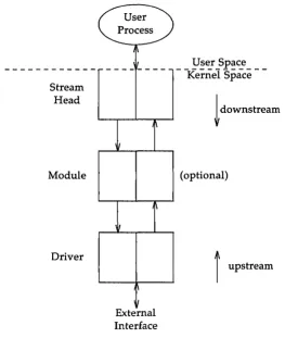
A Stream is a full-duplex processing and data transfer path between a STREAMS driver in kernel space and a process in user space (see Figure 1). In the kernel, a Stream is constructed by linking a stream head, a driver and zero or more modules between the stream head and driver. The Stream head is the end of the Stream closest to the user process. Throughout this guide, the word "STREAMS" will refer to the mechanism and the word "Stream" will refer to the path between a user and a driver.
A STREAMS driver may be a device driver that provides the services of an external I/O device, or a software driver, commonly referred to as a pseudo-device driver, that performs functions internal to a Stream. The Stream head provides the interface between the Stream and user processes. Its principal function is to process STREAMS-related user system calls.
down-Stream Head
Module
Driver
Figure 1: Basic Stream
User Process
~
'1\
,1/
---I~
I
I~
1/
,\ I
External Interface
User Space
- -Kernel
Space
-!
downstream(optional)
f
upstream [image:13.452.103.379.74.385.2]General and STREAMS-specific system calls provide the user level facili-ties required to implement application programs. This system call interface is upwardly compatible with the character I/O facilities. The open(2) sys-tem call will recognize a STREAMS file and create a Stream to the specified driver. A user process can receive and send data on STREAMS files using read(2) and write(2) in the same manner as with character files. The ioctl(2) system call enables users to perform functions specific to a particular device and a set of generic STREAMS ioctl commands [see streamio(7)] support a variety of functions for accessing and controlling Streams. A close(2) will dismantle a Stream.
In addition to the generic ioctl commands, there are STREAMS-specific system calls to support unique STREAMS facilities. The poll(2) system call enables a user to poll multiple Streams for various events. The putmsg(2) and getmsg(2) system calls enable users to send and receive STREAMS mes-sages, and are suitable for interacting with STREAMS modules and drivers through a service interface.
STREAMS provides kernel facilities and utilities to support development of modules and drivers. The Stream head handles most system calls so that the related processing does not have to be incorporated in a module and driver. The configuration mechanism allows modules and drivers to be incorporated into the system.
Examples are used throughout both parts of this document to highlight the most important and common capabilities of STREAMS. The descriptions are not meant to be exhaustive. For simplicity, the examples reference fictional drivers and modules.
Appendix C provides the reference for STREAMS kernel utilities. STREAMS system calls are specified in Section 2 of the Programmer's Refer-ence Manual. STREAMS utilities are specified in Section 1M of the System Administrator's Reference Manual. STREAMS-specific ioctl calls are specified
in streamio(7) of the System Administrator's Reference Manual. The modules
Part 1 of the guide, Application Programming, provides detailed infor-mation, with various examples, on the user interface to STREAMS facilities.
It is intended for application programmers writing to the STREAMS system call interface. Working knowledge of UNIX system user programming, data communication facilities, and the STREAMS Primer is assumed. The
organi-zation of Part 1 is as follows:
• Chapter 1, Basic Operations, describes the basic operations available for constructing, using, and dismantling Streams. These operations are performed using open(2), close(2), read(2), write(2), and ioctl(2). • Chapter 2, Advanced Operations, presents advanced facilities
pro-vided by STREAMS, including: poll(2), a user level I/O polling facil-ity; asynchronous I/O processing support; and a new facility for sam-pling drivers for available resources.
• Chapter 3, Multiplexed Streams, describes the construction of sophis-ticated, multiplexed Stream configurations.
A Simple Stream
Inserting Modules
Module and Driver Control
1-1
1-4
This chapter describes the basic set of operations for manipulating STREAMS entities.
A STREAMS driver is similar to a character I/O driver in that it has one or more nodes associated with it in the file system and it is accessed using the open system call. Typically, each file system node corresponds to a separate minor device for that driver. Opening different minor devices of a driver will cause separate Streams to be connected between a user process and the driver. The file descriptor returned by the open call is used for further access to the Stream. If the same minor device is opened more than once, only one Stream will be created; the first open call will create the Stream, and subsequent open calls will return a file deSCriptor that refer-ences that Stream. Each process that opens the same minor device will share the same Stream to the device driver.
Once a device is opened, a user process can send data to the device using the write system call and receive data from the device using the read system call. Access to STREAMS drivers using read and write is compatible with the character I/O mechanism.
The close system call will close a device and dismantle the associated Stream.
#include <fcntl.11>
main ( ) {
char bJf[ 1024]; int fd, count;
if ((fd
=
open("/dev/ccmn01", o_~)) < 0) perror( "open failed");exit( 1);
while ((count = read(fd, bJf, 1024)) > 0) if (write (fd, buf, count) 1= c:oont) {
perror("write failed"); break;
exit(O) ;
In the example,
I
devI
commOl identifies a minor device of the-____________ t ___ _
Streamhead
communications driver
_ ___ ~s~~ ~pace
Kernel Space
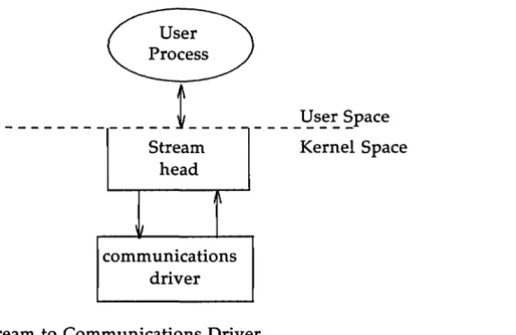
Figure 1-1: Stream to Communications Driver
This example illustrates a user reading data from the communications device and then writing the input back out to the same device. In short, this program echoes all input back over the communications line. The example assumes that a user is sending data from the other side of the com-munications line. The program reads up to 1024 bytes at a time, and then writes the number of bytes just read.
The read call returns the available data, which may contain fewer than 1024 bytes. If no data are currently available at the Stream head, the read call blocks until data arrive.
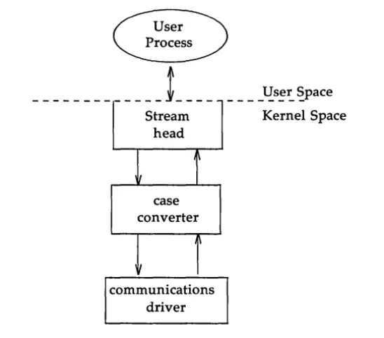
[image:23.452.131.418.72.258.2]An advantage of STREAMS over the existing character I/O mechanism stems from the ability to insert various modules into a Stream to process and manipulate data that passes between a user process and the driver. The following example extends the previous communications device echoing example by inserting a module in the Stream to change the case of certain alphabetic characters. The case converter module is passed an input string and an output string by the user. Any incoming data (from the driver) is inspected for instances of characters in the module's input string and the alphabetic case of all matching characters is changed. Similar actions are taken for outgoing data using the output string. The necessary declarations for this program are shown below:
#include <string.11> #include <fcntl.11> #include <stropts. 11>
1*
* These defines w:ruld typically be * famd in a header file for the m:xiul.e
*1
#define CUl'Pl11' S'IRIN3 1 #define INrur S'1'RlN3 2
main ( )
{
char hlf[ 1024]; int fd, count;
struct strioctl strioctl;
i f ((fd = ope:n("/dev/ccmn01", O)~rnR)) < 0) { pen-or( "open failed");
exit(1);
if (ioct1(fd, I_PUSH, "case_converter") < 0) pen-or( "ioctl I_PUSH failed");
exit(2) ;
---
---Stream head
case converter
\
\~
communications driver Figure 1-2: Case Converter Module
____ ~s~~ ~pace
Kernel Space
An important difference between STREAMS drivers and modules is illustrated here. Drivers are accessed through a node or nodes in the file system and may be opened just like any other device. Modules, on the other hand, do not occupy a file system node. Instead, they are identified through a separate naming convention, and are inserted into a Stream using I_PUSH. The name of a module is defined by the module developer, and is typically included on the manual page describing the module (manual pages describing STREAMS drivers and modules are found in section 7 of the System Administrator's Reference Manual).
[image:26.455.75.349.69.310.2]con-The next step in this example is to pass the input string and output string to the case converter module. This can be accomplished by issuing ioctl calls to the case converter module as follows:
1* set inp.lt canversicm string *1
strioctl.ic_aId = lNRJl'_S'I'RIN3; h cx::mnand type *1
strioctl.ic _ tinolt = 0; 1* default tineout (15 sec) *1
strioctl.ic_dp = "~";
strioctl.ic_len
=
strlen(strioctl.ic_dp);i f (ioctl(fd, I_SIR, &strioctl) < 0)
perror( "ioctl I _ S'IR failed");
exit(3) ;
1* set ouq:ut canversicm strin:J *1
strioctl.ic_aId = 00'I'P0l'_S'lRnG;1* cx::mnand type *1 strioctl. ic _ dp = "abcdefghij";
strioctl. ic _len = strlen( strioctl. ic _ dp) ;
i f (ioctl(fd, I_SIR, &strioctl) < 0)
perror ("ioctl I _ S'IR failed");
exit(4) ;
struct strioctl { } :int :int :int char ic_ard; ic_timJut; ic_len; *ic_dp;
/* ioctl request */ /* ACKINAK timeout */
/* length of data argument */ /* ptr to data argument */
where ic_cmd identifies the command intended for a module or driver, ic_timout specifies the number of seconds an I_STR request should wait for
an acknowledgement before timing out, ic Jen is the number of bytes of data
to accompany the request, and ic_dp points to that data.
I_STR is intercepted by the Stream head, which packages it into a mes-sage, using information contained in the strioctl structure, and sends the message downstream. The request will be processed by the module or driver closest to the Stream head that understands the command specified by ic_cmd. The ioctl call will block up to ic_timout seconds, waiting for the
target module or driver to respond with either a positive or negative ack-nowledgement message. If an acknowledgement is not received in ic_timout
seconds, the ioctl call will fail.
I_STR is actually a nested request; the Stream head intercepts I_STR and then sends the driver or module request (as specified in the strioctl struc-ture) downstream. Any module that does not understand the command in
ic_cmd will pass the message further downstream. Eventually, the request
will reach the target module or driver, where it is processed and ack-nowledged. If no module or driver understands the command, a negative acknowledgement will be generated and the ioctl call will fail.
In the example, two separate commands are sent to the case converter module. The first contains the conversion string for input data, and the second contains the conversion string for output data. The ic _cmd field is
set to indicate whether the command is setting the input or output conver-sion string. For each command, the value of ic _timout is set to zero, which
specifies the system default timeout value of 15 seconds. Also, a data argu-ment that contains the conversion string accompanies each command. The
ic_dp field points to the beginning of each string, and icJen is set to the
Only one I_STR request can be active on a STREAM at one time. Further requests will block until the active I_STR request is acknowledged and the system call completes.
The strioctl structure is also used to retrieve the results, if any, of an I_STR request. If data is returned by the target module or driver, ic_dp must
point to a buffer large enough to hold that data, and icjen will be set on
return to indicate the amount of data returned.
The remainder of this example is identical to the previous example:
while «count = read(fd, buf, 1024» > 0) if (write (fd, buf, count) 1= count) {
perror( "write failed");
break;
exit(O) ;
The case converter module will convert the specified input characters to lower case, and the corresponding output characters to upper case. Notice that the case conversion processing was realized with no change to the
com-munications driver.
A few of the important ioctl requests supported by STREAMS have been
Advanced Input/Output Facilities
Input/Output Polling
Asynchronous Input / Output
Clone Open
2-1
2-2
2-7
The poll(2) system call provides users with a mechanism for monitoring input and output on a set of file descriptors that reference open Streams. It
identifies those Streams over which a user can send or receive data. For each Stream of interest users can specify one or more events about which they should be notified. These events include the following:
POLLIN Input data is available on the Stream associated with the given file descriptor.
POLLPRI A priority message is available on the Stream associated with the given file descriptor. Priority messages are described in the section of Chapter 4 entitled "Accessing the Datagram Provider."
POLLOUT The Stream associated with the given file is writable. That is, the Stream has relieved the flow control that would prevent a user from sending data over that Stream.
poll will examine each file descriptor for the requested events and, on return, will indicate which events have occurred for each file descriptor. If
no event has occurred on any polled file descriptor, poll blocks until a requested event or timeout occurs. The specific arguments to poll are the following:
• an array of file descriptors and events to be polled • the number of file descriptors to be polled
• the number of milliseconds poll should wait for an event if no events are pending (-1 specifies wait forever)
#include <fcnt1.h> #include <poll.h>
#define NroLL 2 /* number of file descriptors to poll */ nain( )
{
stJ:uct p:>llfd pollfds[NroLL] j
char blf[ 1024] j int COImt, i;
if «pollfds[O].fd = open("/dev/ccmn01", O)U:MR:O_NDELAY» < 0) { perror( "open failed for /dev/ccmn01") j
exit(1) ;
i f «pollfds[1].fd = open("/dev/ccmn02", O)Ul'lR.:O_NDELAY» < 0) { perror( "open failed for /dev/ccmn02");
exit(2) ;
The variable pollfds is declared as an array of pollfd structures, where
this structure is defined in <poll.h> and has the following format:
stroct pollfd {
}
int fd; short events; short revents;
1* file descriptor *1 1* requested events *1 1* returned events *1
For each entry in the array, fd specifies the file descriptor to be polled
and events is a bitmask that contains the bitwise inclusive OR of events to
be polled on that file descriptor. On return, the revents bitmask will
The example opens two separate minor devices of the communications driver and initializes the pollfds entry for each. The remainder of the
exam-ple uses poll to process incoming data as follows:
1* set events to p:>1l for inc::anin:J data *1
p:>llfds [0] • events = rolLIN;
p:>llfds [ 1 ] • events = rolLIN;
while (1) {
1* p:>1l ani use -1 timeout (infinite) *1
if (p:>ll(p:>llfds, NPOLL, -1) < 0) { pen:or( "p:>1l failed");
exit(3);
for (i = 0; i < NPOLL; i++) {
switch (p:>llfds [i]. revents) default:
perrar( "error event"); exit(4) ;
case 0: break;
case roLLIN:
1* default error case *1
1* echo inc::anin:J data an "other" stream *1
while «count = read(p:>llfds[i] .fd, buf, 1024» > 0)
1*
* the write loses data i f flCM control * prevents the transmit at this time.
*1
The user specifies the polled events by setting the events field of the
poll£d structure to POLLIN. This requested event directs poll to notify the user of any incoming data on each Stream. The bulk of the example is an infinite loop, where each iteration will poll both Streams for incoming data.
The second argument to poll specifies the number of entries in the
pollfds array (2 in this example). The third argument is a timeout value
indicating the number of milliseconds poll should wait for an event if none has occurred. On a system where millisecond accuracy is not available,
timeout is rounded up to the nearest legal value available on that system.
Here, the value of timeout is -1, specifying that poll should block
indefinitely until a requested event occurs or until the call is interrupted.
If poll succeeds, the program looks at each entry in pollfds. If revents is
set to 0, no event has occurred on that file descriptor. If revents is set to
POLLIN, incoming data is available. In this case, all available data is read from the polled minor device and written to the other minor device.
If revents is set to a value other than 0 or POLLIN, an error event must
have occurred on that Stream, because the only requested event was POL-LIN. The following error events are defined for poll. These events may not be polled for by the user, but will be reported in revents whenever they
occur. As such, they are only valid in the revents bitmask:
POLLERR A fatal error has occurred in some module or driver on the Stream associated with the specified file descriptor.
Further system calls will fail.
POLLHUP A hangup condition exists on the Stream associated with the specified file descriptor.
POLLNVAL The specified file descriptor is not associated with an open Stream.
The example attempts to process incoming data as quickly as possible. However, when writing data to a Stream, the write call may block if the Stream is exerting flow control. To prevent the process from blocking, the minor devices of the communications driver were opened with the
0_ NDELA Y flag set. If flow control is exerted and 0 _ NDELA Y is set, write will not be able to send all the data. This can occur if the communications driver is unable to keep up with the user's rate of data transmission. If the Stream becomes full, the number of bytes write sends will be less than the requested count. For simplicity, the example ignores the data if the Stream
The poll system call described above enables a user to monitor multiple Streams in a synchronous fashion. The poll call normally blocks until an event occurs on any of the polled file descriptors. In some applications, however, it is desirable to process incoming data asynchronously. For example, an application may wish to do some local processing and be inter-rupted when a pending event occurs. Some time-critical applications cannot afford to block, but must have immediate indication of success or failure.
A new facility is available for use with STREAMS that enables a user process to request a signal when a given event occurs on a Stream. When used with poll, this facility enables applications to asynchronously monitor a set of file descriptors for events.
The I_SETSIG ioctl call [see streamio(7)] is used to request that a SIG-POLL signal be sent to a user process when a specific event occurs. Listed below are the events for which an application may be signaled:
S_INPUT S HIPRI S_OUTPUT
Data has arrived at the Stream head, and no data existed at the Stream head when it arrived.
A priority STREAMS message has arrived at the Stream head.
The Stream is no longer full and can accept output. That is, the Stream has relieved the flow control that would prevent a user from sending data over that Stream. A special STREAMS signal message that contains a
SIG-POLL signal has reached the front of the Stream head input queue. This message may be sent by modules or drivers to generate immediate notification of data or events to follow.
In the earlier examples, each user process connected a Stream to a driver by opening a particular minor device of that driver. Often, however, a user process wants to connect a new Stream to a driver regardless of which minor device is used to access the driver.
In the past, this typically forced the user process to poll the various minor device nodes of the driver for an available minor device. To alleviate this task, a facility called clone open is supported for STREAMS drivers. If
a STREAMS driver is implemented as a cloneable device, a single node in the file system may be opened to access any unused minor device. This spe-cial node guarantees that the user will be allocated a separate Stream to the driver on every open call. Each Stream will be associated with an unused minor device, so the total number of Streams that may be connected to a cloneable driver is limited by the number of minor devices configured for that driver.
The clone device may be useful, for example, in a networking environ-ment where a protocol pseudo-device driver requires each user to open a separate Stream over which it will establish communication. Typically, the users would not care which minor device they used to establish a Stream to the driver. Instead, the clone device can find an available minor device for each user and establish a unique Stream to the driver. Chapter 3 describes this type of transport protocol driver.
Multiplexor Configurations
Building a Multiplexor
Dismantling a Multiplexor
Routing Data Through a Multiplexor
3-1
3-4
3-14
In the earlier chapters, Streams were described as linear connections of modules, where each invocation of a module is connected to at most one upstream module and one downstream module. While this configuration is suitable for many applications, others require the ability to multiplex Streams in a variety of configurations. Typical examples are terminal win-dow facilities, and internetworking protocols (which might route data over several subnetworks).
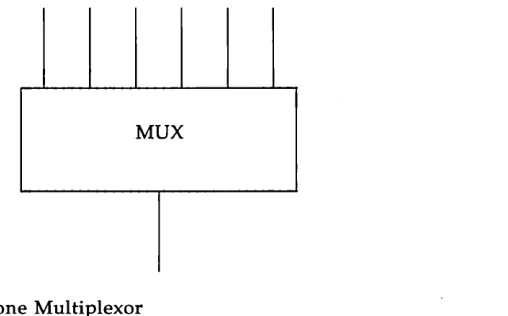
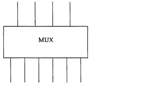
An example of a multiplexor is one that multiplexes data from several upper Streams over a single lower Stream, as shown in Figure 3-1. An upper Stream is one that is upstream from a multiplexor, and a lower Stream is one that is downstream from a multiplexor. A terminal window-ing facility might be implemented in this fashion, where each upper Stream is associated with a separate window.
[image:43.450.160.414.259.417.2]MUX
Figure 3-1: Many-to-one Multiplexor
MUX
Figure 3-2: One-to-many Multiplexor
A third type of multiplexor might route data from one of many upper Streams to one of many lower Streams, as shown in Figure 3-3.
MUX
[image:44.451.136.384.316.459.2]A STREAMS mechanism is available that supports the multiplexing of Streams through special pseudo-device drivers. Using a linking facility, users can dynamically build, maintain, and dismantle each of the above multiplexed Stream configurations. In fact, these configurations can be further combined to form complex, multi-level multiplexed Stream configurations.
The remainder of this chapter describes multiplexed Stream
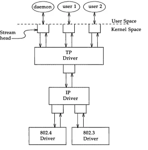
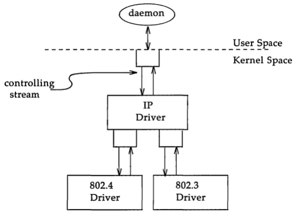
configurations in the context of an example (see Figure 3-4). In this exam-ple, an internetworking protocol pseudo-device driver (IP) is used to route data from a single upper Stream to one of two lower Streams. This driver supports two STREAMS connections beneath it to two distinct
sub-networks. One sub-network supports the IEEE 802.3 standard for the CSMA/ CD medium access method. The second sub-network supports the IEEE 802.4 standard for the token-passing bus medium access method.
Figure 3-4 shows the multiplexing configuration to be created. This configuration will enable users to access the services of the transport proto-col. To free users from the need to know about the underlying protocol structure, a user-level daemon process will build and maintain the multi-plexing configuration. Users can then access the transport protocol directly by opening the TP driver device node.
Stream head
[image:46.450.71.368.168.468.2]802.4 Driver
Figure 3-4: Protocol Multiplexor TP Driver
IP
Driver
802.3 Driver
The following example shows how this daemon process sets up the pro-tocol multiplexor. The necessary declarations and initialization for the dae-mon program are as follows:
#include <fc:ntl.h> #include <stropts. h>
nain( )
{
int fd_802_4, fd_802_3, fd_ip, fd_tp; 1*
* daem:m-ize this process *1
switch (fork( )) {
case 0:
break;
case -1:
perror( "fork failed"); exit(2) ;
default:
exit(O) ;
setpgrp( );
This multi-level multiplexed Stream configuration will be built from the bottom up. Therefore, the example begins by constructing the IP multi-plexor. This multiplexing pseudo-device driver is treated like any other software driver. It owns a node in the UNIX file system and is opened just like any other STREAMS device driver.
~emov
_
L _____
~
______
l!:s_e:
~£ace
[image:48.450.48.387.288.514.2]802.4 Driver Figure 3-5: Before Link
IP Driver
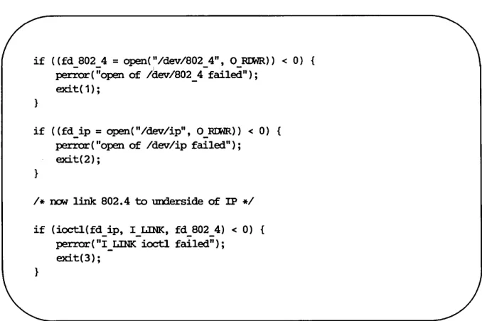
The sequence of instructions to this point is:
if ((fd 8024 = open("/dev/802 4", ORIMR» < 0) {
~(;;open of /dev/802_4-failed"); exit(1);
if ((fd_ip=open("/dev/ip", O)~I:MR» < 0) {
perror("Open of /dev/ip failed"); exit(2) ;
/ * DCM link 802.4 to underside of IP */ if (ioctl(fd_ip, I_LINK, fd_802_4) < 0) {
perror( "I_LINK ioctl failed"); exit(3);
I_LINK takes two file descriptors as arguments. The first file descriptor,
fd~p, must reference the Stream connected to the multiplexing driver, and
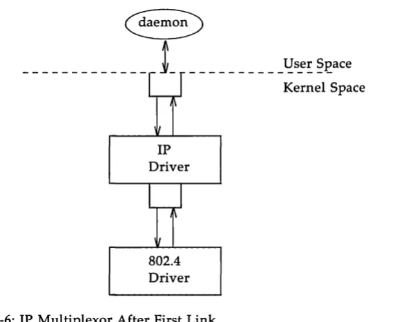
the second file descriptor, fd_B02_4, must reference the Stream to be con-nected below the multiplexor. Figure 3-6 shows the state of these Streams following the I_LINK call. The complete Stream to the 802.4 driver has been connected below the IP driver, including the Stream head. The Stream head of the 802.4 driver will be used by the IP driver to manage the multiplexor.
__________ ~s_e: ~~ace
Kernel Space
IP Driver
[image:49.451.101.395.171.404.2]802.4 Driver Figure 3-6: IP Multiplexor After First Link
The following sequence of system calls is used to continue building the internetworking multiplexor (IP):
if ((fd_S02_3 = open("/dev/S02_3", O}~IMR» < 0) perror("open of /dev/S02_3 failed");
exit(4);
if (ioctl(fd_ip, I_LINK, fd_S02_3) < 0) perror( "I_LINK ioctl failed");
exit(S) ;
controllinJ stream
Figure 3-7: IP Multiplexor 802.4 Driver
__________ ~s!~ §£ace Kernel Space
IP Driver
802.3 Driver
The Stream above the multiplexing driver used to establish the lower connections is the controlling Stream and has special significance when dis-mantling the multiplexing configuration, as will be illustrated later in this chapter. The Stream referenced by fdJp is the controlling Stream for the IP
multiplexor.
The number of Streams that can be linked to a multiplexor is restricted by the design of the particular multiplexor. The manual page describing each driver (typically found in section 7 of the System Administrator's Refer-ence Manual) should describe such restrictions. However, only one I_LINK
operation is allowed for each lower Stream; a single Stream cannot be linked below two multiplexors simultaneously.
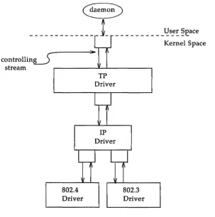
Continuing with the example, the IP driver will now be linked below the transport protocol (TP) multiplexing driver. As seen earlier in Figure 3-4, only one link will be supported below the transport driver. This link is formed by the following sequence of system calls:
if «fd_tp = open("/dev/tp", O)~IMR» < 0) { perror( "open of /dev/tp failed");
ex:it(6) ;
if (ioctl(fd_tp, I_LINK, fd_ip) < 0) perror("I_LINK ioctl failed");
ex:it(7) ;
controllinJ
__________ ~s_e~ §£ace Kernel Space stream ,....-_ _ _ _ - J L - - ' -_ _ _ _ _ ...,
[image:53.452.96.400.75.381.2]802.4 Driver Figure 3-8: TP Multiplexor
TP Driver
IP Driver
802.3 Driver
Because the controlling Stream of the IP multiplexor has been linked below the TP multiplexor, the controlling Stream for the new multi-level multiplexor configuration is the Stream above the TP multiplexor.
and putmsg system calls issued to them will fail. That is because I_LINK associates the Stream head of each linked Stream with the multiplexor, so the user may not access that Stream directly for the duration of the link.
The following sequence of system calls will complete the multiplexing daemon example:
close(fd_802_4); close(fd_802_3) ; close (fd_ ip);
1* Hold nultiplexor open forever *1
pause() ;
Figure 3-4 shows the complete picture of the level protocol multi-plexor. The transport driver is designed to support several, simultaneous virtual circuits, where these virtual circuits map one-to-one to Streams opened to the transport driver. These Streams will be multiplexed over the single Stream connected to the IP multiplexor. The mechanism for estab-lishing multiple Streams above the transport multiplexor is actually a by-product of the way in which Streams are created between a user process and a driver. By opening different minor devices of a STREAMS driver, separate Streams will be connected to that driver. Of course, the driver must be designed with the intelligence to route data from the single lower Stream to the appropriate upper Stream.
[image:54.452.49.382.142.277.2]Streams connected to a multiplexing driver from above with open, can be dismantled by closing each Stream with close. In the protocol multi-plexor, these Streams correspond to the virtual circuit Streams above the TP multiplexor. The mechanism for dismantling Streams that have been linked below a multiplexing driver is less obvious, and is described below in detail.
The I_UNLINK ioctl call is used to disconnect each multiplexor link below a multiplexing driver individually. This command takes the follow-ing form:
ioctl(fd, I_UNLINK, mux_id);
where fd is a file descriptor associated with a Stream connected to the
multi-plexing driver from above, and muxJd is the identifier that was returned by
I_LINK when a driver was linked below the multiplexor. Each lower driver may be disconnected individually in this way, or a special muxJd value of -1
may be used to disconnect all drivers from the multiplexor simultaneously. In the multiplexing daemon program presented earlier, the multiplexor is never explicitly dismantled. That is because all links associated with a multiplexing driver are automatically dismantled when the controlling Stream associated with that multiplexor is closed. Because the controlling Stream is open to a driver, only the final call of close for that Stream will close it. In this case, the daemon is the only process that has opened the controlling Stream, so the multiplexing configuration will be dismantled when the daemon exits.
For the automatic dismantling mechanism to work in the multi-level, multiplexed Stream configuration, the controlling Stream for each multi-plexor at each level must be linked under the next higher level multimulti-plexor. In the example, the controlling Stream for the IP driver was linked under the TP driver. This resulted in a single controlling Stream for the full, multi-level configuration. Because the multiplexing program relied on clos-ing the controllclos-ing Stream to dismantle the multiplexed Stream
As demonstrated, STREAMS has provided a mechanism for building multiplexed Stream configurations. However, the criteria on which a plexor routes data is driver dependent. For example, the protocol multi-plexor shown in the last example might use address information found in a protocol header to determine over which sub-network a given packet should be routed. It is the multiplexing driver's responsibility to define its routing criteria.
Service Interface Messages
Service Interfaces
The Message Interface
Datagram Service Interface Example
Accessing the Datagram Provider Closing the Service
Sending a Datagram Receiving a Datagram
4-1 4-1
4-4
A STREAMS message format has been defined to simplify the design of service interfaces. Also, two new system calls, getmsg(2) and putmsg(2) are available for sending these messages downstream and receiving messages that are available at the Stream head. This chapter describes these system calls in the context of a service interface example. First, a brief overview of STREAMS service interfaces is presented.
Service Interfaces
A principal advantage of the STREAMS mechanism is its modularity. From user level, kernel-resident modules can be dynamically interconnected to implement any reasonable processing sequence. This modularity reflects the layering characteristics of contemporary network architectures.
One benefit of modularity is the ability to interchange modules of like function. For example, two distinct transport protocols, implemented as STREAMS modules, may provide a common set of services. An application or higher layer protocol that requires those services can use either module. This ability to substitute modules enables user programs and higher level protocols to be independent of the underlying protocols and physical com-munication media.
Application A
- - - -- -
- ---Service Interfac
... ...
TCP
Transport Protocol
[image:62.456.45.389.70.305.2]Lower Layer Protocol Suite A
Figure 4-1: Protocol Substitution
Application A
---
-
-
-
--e ... ...
ISO
Transport Protocol
Lower Layer Protocol Suite B
_ !:1
~er Space Kernel SpaceBy defining a service interface through which applications interact with a transport protocol, it is possible to substitute a different protocol below that service interface in a manner completely transparent to the application. In this example, the same application can run over the Transmission Con-trol Protocol (TCP) and the ISO transport protocol. Of course, the service interface must define a set of services common to both protocols.
Request Primitiv
~
es
[image:63.452.88.416.76.297.2]...
Figure 4-2: Service Interface
Service User
Service Interface
... ...
t
R esponse and
E vent Primitives
,
Service Provider
A message format has been defined to simplify the design of service interfaces using STREAMS. Each service interface primitive is a distinct STREAMS message that has two parts: a control part and a data part. The control part contains information that identifies the primitive and includes all necessary parameters. The data part contains user data associated with that primitive.
An example of a service interface primitive is a transport protocol con-nect request. This primitive requests the transport protocol service provider to establish a connection with another transport user. The parameters asso-ciated with this primitive may include a destination protocol address and specific protocol options to be associated with that connection. Some tran-sport protocols also allow a user to send data with the connect request. A STREAMS message would be used to define this primitive. The control part would identify the primitive as a connect request and would include the protocol address and options. The data part would contain the associated user data.
STREAMS enables modules to create these messages and pass them to neighbor modules. However, the read and write system calls are not sufficient to enable a user process to generate and receive such messages. First, read and write are byte-stream oriented, with no concept of message boundaries. To support service interfaces, the message boundary of each service primitive must be preserved so that the beginning and end of each primitive can be located. Also, read and write offer only one buffer to the user for transmitting and receiving STREAMS messages. If control informa-tion and data were placed in a single buffer, the user would have to parse the contents of the buffer to separate the data from the control information.
Two new STREAMS system calls are available that enable user processes to create STREAMS messages and send them to neighboring kernel modules and drivers or receive the contents of such messages from kernel modules and drivers. These system calls preserve message boundaries and provide separate buffers for the control and data parts of a message.
sys-The syntax of putmsg is as follows:
int putmsg (fd, ctIptr, dataptr, flags) int fd;
struct strbuf *ct1ptr; struct strbuf ~taptr;
int flags;
fd identifies the Stream to which the message will be passed, ctlptr and dataptr identify the control and data parts of the message, and flags may be
used to specify that a priority message should be sent.
The strbu£ structure is used to describe the control and data parts of a message, and has the following format:
struct strbuf {
int naxlen;
int len;
char *buf;
1* nax:imum buffer lenrth *1 1* lenrth of data *1
1* pointer to buffer *1 }
buf points to a buffer containing the data and len specifies the number of
bytes of data in the buffer. maxlen specifies the maximum number of bytes
the given buffer can hold, and is only meaningful when retrieving informa-tion into the buffer using getmsg.
The getmsg system call retrieves messages available at the Stream head, and has the following syntax:
int getmsg (fd, ctIptr, dataptr, flags) int fd;
struct strbuf *ct1ptr; struct strbuf ~taptr;
int *flags;
The arguments to getmsg are the same as those for putmsg.
The example datagram service interface library presented below includes four functions that enable a user to do the following:
• establish a Stream to the service provider and bind a protocol address to the Stream
• send a datagram to a remote user • receive a datagram from a remote user • close the Stream connected to the provider
First, the structure and constant definitions required by the library are shown. These typically will reside in a header file associated with the ser-vice interface.
1*
* Pr:imi ti ves initiated by the service user.
*1
#define BIND RID 1* bini request *1
#define UNI'IDATA RID 2 1* unitdata request *1
1*
* Pr:imitives initiated by the service provider.
*1
#define a< N:K 3
#define ERRCR N:K 4
#define UNI'IDATA IND 5
1* bini ackn:lwledgment *1 1* error ackn:lwledgment *1 1* unitdata indication *1
1*
* The follCMiDJ structure definitions define the fonnat of the
* control part of the service interface message of the above
* pr:imi tives.
stru.ct bini _ req { lan:J PRIM_type; lan:J BIND _ addr;
};
struct unitdata _ req { lc:D] PRIM_type; lc:D] DEST _ addr;
} ;
struct ok _ ack {
};
struct error _ ack { lc:D] PRIM_type; lc:D] UNIX_error;
} ;
struct uni tdata _:in:i {
lc:D] PRIM_type; lc:D] SRC _ addr;
};
1* unitdata request *1 1* always UNI'lnr\TA)ID';! *1 1* destination addr *1
1* positive acknowledgment *1 1* always ($.-,>1::1< *1
1* error acknowledgment *1 1* always ERRCR-,!CK *1 1* UNIX error code *1
1* unitdata :in:iication *1 1* always UNI'lnr\TA _!NO *1 1* source addr *1
1* union of all primitives *1
union primitives {
lc:D] type;
};
struct bind _ req struct unitdata_req struct ok ack struct error ack struct uni tdata :in:i
b:in:i _ req; unitdata _ req; ok_ack; error_ack; unitdata _ :in:i;
1* header files needed by li.brazy *1
#include <stropts. h>
#include <stdio. h>
#include <errrx>. h>
continued
Five primitives have been defined. The first two represent requests from the service user to the service provider. These are:
UNITDATA_REQ
This request asks the provider to send a datagram to the specified destination address. It does not require an acknowledgement from the provider.
The three other primitives represent acknowledgements of requests, or indications of incoming events, and are passed from the service provider to the service user. These are:
OK_ACK This primitive informs the user that a previous bind request was received successfully by the service pro-vider.
ERROR_ACK This primitive informs the user that a non-fatal error was found in the previous bind request. It indicates that no action was taken with the primitive that caused the error.
UNITDATA IND
This primitive indicates that a datagram destined for the user has arrived.
The structures defined above describe the contents of the control part of each service interface message passed between the service user and service provider. The first field of each control part defines the type of primitive being passed.
Accessing the Datagram Provider
The first routine presented below, inter _open, opens the protocol driver device file specified by path and binds the protocol address contained in
inter _ open (pa:th, oflags, addr) char *path;
{
int fd;
struct bind _ req bind Jeq; struct strbuf ctlbuf; union primitives rcvhlf; struct error _ ack *error _ ack; int flags;
i f ((fd = open(path, oflags» < 0) return(-1) ;
1* sem bind request msg down stream *1
bind _ req. PRIM_type = BIND }IDJ;
bind _ req. BIND _ addr = addr;
ct1buf.len = sizeof(struct bind_req); ct1buf . buf = (char * ) &bind _ req;
if (putmsg(fd, &ctlbuf, NULL, 0) < 0) close(fd) ;
return(-1) ;
After opening the protocol driver, inter _open packages a bind request message to send downstream. putmsg is called to send the request to the service provider. The bind request message contains a control part that holds a bind _req structure, but it has no data part. ctlbuf is a structure of type strbuf, and it is initialized with the primitive type and address. Notice that the maxlen field of ctlbuf is not set before calling putmsg. That is because putmsg ignores this field. The dataptr argument to putmsg is set to NULL to indicate that the message contains no data part. Also, the flags argument is 0, which specifies that the message is not a priority message.
1* wait for ack of request *1
ctlblf .maxlen = sizeof (tmian primitives); ctlblf . len = 0;
ctlblf . buf = (char * )&rcvbuf; flags
=
RS_HIP.RI;if (ge1:lnsg(fd, &ctlbuf, NULL, &flags) < 0) { close(fd) ;
return(-1) ;
1* did we get eoouqh to detennine type *1
if (ctlbuf • len < sizeof (lCDJ» { close(fd) ;
errno = EPROm;
return(-1) ;
1* switch on type (first 1()D:J in rcvl:uf) *1
switch( rcvbuf • type) {
default:
errno = EPROm;
close(fd) ; return(-1);
case OK PCK.: return(fd) ;
case ERROR PCK.:
if (ctlb.lf.len < sizeof(st:ruct error_ack» errno = EPROm;
close(fd); return(-1) ;
error _ ack = (st:ruct error _ ack * )&rcvl:uf; errno = error_ack->UNIX_error;
getmsg is called to retrieve the acknowledgement of the bind request. The acknowledgement message consists of a control part that contains either an ok_ack or error _ack structure, and no data part.
The acknowledgement primitives are defined as priority messages. Two classes of messages can arrive at the Stream head: priority and normal. Nor-mal messages are queued in a first-in-first-out manner at the Stream head, while priority messages are placed at the front of the Stream head queue. The STREAMS mechanism allows only one priority message per Stream at the Stream head at one time; any further priority messages are discarded until the first message is processed. Priority messages are particularly suit-able for acknowledging service requests when the acknowledgement should be placed ahead of any other messages at the Stream head.
These messages are not intended to support the expedited data capabilities of many communication protocols, as evidenced by the one-at-a-time res-triction just described.
Before calling getmsg, this routine must initialize the strbuf structure for the control part. but should point to a buffer large enough to hold the expected control part, and maxlen must be set to indicate the maximum number of bytes this buffer can hold.
Because neither acknowledgement primitive contains a data part, the
dataptr argument to getmsg is set to NULL. The flags argument points to an integer containing the value RS_HIPRI. This flag indicates that getmsg should wait for a STREAMS priority message before returning, and is set because the acknowledgement primitives are priority messages. Even if a normal message is available, getmsg will block until a priority message arrives.
Closing the Service
The next routine in the datagram service library is inter _close, which closes the Stream to the service provider.
close(fd);
The routine simply closes the given file descriptor. This will cause the protocol driver to free any resources associated with that Stream. For exam-ple, the driver may unbind the protocol address that had previously been bound to that Stream, thereby freeing that address for use by some other service user.
Sending a Datagram
The third routine, inter _snd, passes a datagram to the service provider for transmission to the user at the address specified in addr. The data to be transmitted is contained in the buffer pointed to by but and contains len
bytes. On successful completion, this routine returns the number of bytes of data passed to the service provider; on failure, it returns -1 and sets errno
inter_snd(fd, rut, len, addr)
char *buf;
1<D;J addr;
{
struct strrut ctlruf;
struct strrut databuf;
struct unitdata_req unitdata_req;
unitdata _ req. PRIM_type = UNI'lDATA _run; unitdata _ req. DEST _ addr = addr;
ct1buf.len = sizeof(struct unitdata_req); ct1buf • rut = (char * )&unitdata _ req; databuf.len
=
len;databuf.rut = rut;
if (plbnsg (fd, &ctlruf, &databuf, 0) < 0) return(-1);
return( len) ;
In this example, the datagram request primitive is packaged with both a control part and a data part. The control part contains a unitdata_req
struc-ture that identifies the primitive type and the destination address of the datagram. The data to be transmitted is placed in the data part of the request message.
Receiving a Datagram
The final routine in this example, inter _rev, retrieves the next available
datagram. but points to a buffer where the data should be stored, len
indi-cates the size of that buffer, and addr points to a long integer where the source address of the datagram will be placed. On successful completion,
inter _rev returns the number of bytes in the retrieved datagram; on failure, it
returns -1 and sets the appropriate UNIX system error value.
inter _ rcv(fd, b.lf, len, addr) char *b.lf;
lCID1 *addr;
{
struct strbut ctll::uf; struct strbut datab.lf;
struct unitdata _ iIrl unitdata _ iIrl; int retval;
int flags;
ctlb.lf.maxlen = sizeof(st:ruct unitdata_ind); ctlb.lf • len = 0;
ctlb.lf • but = (char * )&unitdata _ irxi; databuf .maxlen = len;
databuf • len = 0; databuf . b.lf = b.lf; flags = 0;
if
«
retval = getmsg (fd, &ctll::uf, &databuf, &flags» < 0) return ( -1);i f (unitdata _ iIrl. PRIM_type 1= UNI'IDATA _lND)
er.rno = EPROro;
return ( -1);
if (retval) {
er.rno = ErO; return ( -1);
getmsg is called to retrieve the datagram indication primitive, where that primitive contains both a control and data part. The control part con-sists of a unitdata_ind structure that identifies the primitive type and the source address of the datagram sender. The data part contains the data itself.
In ctlbut, but must point to a buffer where the control information will be stored, and maxlen must be set to indicate the maximum size of that buffer. Similar initialization is done for databut.
The flags argument to getmsg is set to zero, indicating that the next mes-sage should be retrieved from the Stream head, regardless of its priority. Datagrams will arrive in normal priority messages. If no message currently exists at the Stream head, getmsg will block until a message arrives.
The user's control and data buffers should be large enough to hold any incoming datagram. If both buffers are large enough, getmsg will process the datagram indication and return 0, indicating that a full message was retrieved successfully. However, if either buffer is not large enough, getmsg will only retrieve the part of the message that fits into each user buffer. The remainder of the message is saved for subsequent retrieval, and a positive, non-zero value is returned to the user. A return value of
MORECTL indicates that more control information is waiting for retrieval. A return value of MOREDATA indicates that more data is waiting for retrieval. A return value of MORECTLjM:OREDATA indicates that data from both parts of the message remain. In the example, if the user buffers are not large enough (that is, getmsg returns a positive, non-zero value), the function will set errno to EIO and fail.
The type of the primitive returned by getmsg is checked to make sure it is a datagram indication. The source address is then set and the number of bytes of data in the datagram is returned.
Part 2 of this guide, Module and Driver Programming, describes the use of STREAMS kernel facilities for developing and installing modules and drivers. It is intended for system programmers with knowledge of UNIX system kernel programming, device driver development, and networking and other data communication facilities. Knowledge of the STREAMS Primer
and the Driver Design Guide is assumed.
STREAMS provides module and driver developers with integral func-tions, a set of utility routines, and facilities that expedite design and imple-mentation. The principle development facilities are listed below:
• Message storage management - to maintain STREAMS's own memory resources for message storage
• Flow control - to conserve STREAMS memory and processing resources
• Scheduling - to control the execution of service procedures • Multiplexing - to switch data among multiple Streams
• Error and trace loggers - for debugging and administrative use Part 2 is organized as follows:
• Chapter 5, Streams Mechanism, reviews the operation of STREAMS and describes how a Stream is constructed and dismantled.
• Chapter 6, Modules, describes the basic STREAMS data structures and the organization of a module.
• Chapter 7, Messages, introduces message blocks, read and write sys-tem calls, and the message storage pool.
• Chapter 8, Message Queues and Service Procedures, discusses put and service procedures, message queueing and basic flow control.
• Chapter 9, Drivers, describes STREAMS driver organization and discusses typical driver processing.
• Chapter 11, Multiplexing, describes the multiplexing facility. • Chapter 12, Service Interface, discusses service interfaces within a
Stream and at the Stream/user boundary.
• Chapter 13, Advanced Topics, contains advanced topics including sig-nals and Stream head options.
• Appendix A, Kernel Structures, summarizes kernel structures used by modules and drivers.
• Appendix B, Message Types, describes STREAMS message types. • Appendix C, Utilities, specifies the STREAMS kernel utility routines. • Appendix D, Design Guidelines, summarizes module and driver
design guidelines.
• Appendix E, Configuring, describes how modules and drivers are configured into the UNIX system, tunable parameters and STREAMS system error messages.
Overview
Stream Construction
Opening a Stream
Adding and Removing Modules
Closing
5-1
5-3
5-5
5-6
A Stream implements a connection within the kernel between a driver in kernel space and a process in user space. It provides a general character input/output (I/O) interface for user processes which is upwardly compati-ble with the interface of the preexisting character I/O facilities. A Stream is analogous to a shell pipeline except that data flow and processing are bidirectional to support concurrent input and output.
The components that form a Stream are the Stream head, driver and optional modules (see Figure 1 in the Preface). A Stream is initially con-structed as the result of a user process open(2) system call referencing a STREAMS file. The call causes a kernel resident driver to be connected with a Stream head to form a Stream. Subsequent ioctl(2) calls select kernel resident modules and cause them to be inserted in the Stream. A module represents intermediate processing on messages flowing between the Stream head and driver. A module can function as, for example, a communication protocol, line discipline or data filter. STREAMS allows a user to connect a module with any other module. The user determines the module connec-tion sequences that result in useful configuraconnec-tions.
A process can send and receive characters on a Stream using write(2) and read(2), as on character files. When user data enters the Stream head or external data enters the driver, the data is placed into messages for
transmission on the Stream. All data passed on a Stream is carried in mes-sages, each having a defined message type identifying the message contents. Internal control and status information is transmitted among modules or between the Stream and user process as messages of certain types inter-leaved on the Stream. Modules and drivers can send certain message types to the Stream head to cause the generation of signals or errors to be
received by the user process.
The last dose(2) system call dismantles the Stream and closes the file, semantically identical to character I/O drivers.
STREAMS constructs a Stream as a linked list of kernel resident data structures. In a STREAMS file, the inode points to the Stream header struc-ture. The header is used by STREAMS kernel routines to perform opera-tions on this Stream generally related to system calls. Figure 5-1 depicts the downstream (write) portion of a Stream (see Chapter 3 of the Primer) con-nected to the header. There is one header per Stream. From the header onward, a Stream is constructed of QUEUEs. The upstream (read) portion of the Stream (not shown in Figure 5-1) parallels the downstream portion in the opposite direction and terminates at the Stream header structure.
[image:83.450.65.407.200.240.2]Stream header QUEUE H QUEUE PI
Figure 5-1: Downstream Stream Construction
QUEUE P2
QUEUE
D
At the same relative location in each QUEUE is the address of the entry point, a procedure to be executed on any message received by that QUEUE. The procedure for QUEUE H, at one end of the Stream, is the STREAMS provided Stream head routine. QUEUE H is the downstream half of the Stream head. The procedure for QUEUE D, at the other end, is the driver routine. QUEUE D is the downstream half of the Stream end. PI and P2
are pushable modules, each containing their own unique procedures. That is, all STREAMS components are of similar organization.
This similarity results in the uniform manner of navigating in either direction on a Stream: messages move from one end to the other, from QUEUE to the next linked QUEUE, executing the procedure specified in the QUEUE.
module _stat upstream read downstream
/
II q_qinfo qinit write:>
~
queue_t module Jnfo q_next II q_qinfo f- - - - -->
read write
:>
queue_t
upstream V downstream
Figure 5-2: QUEUE Data Structures
Figure 5-1 shows QUEUE linkage in one direction while Figure 5-2 shows two neighboring modules with links (solid vertical arrows) in both directions. When a module is pushed onto a Stream, STREAMS creates two QUEUEs and links each QUEUE in the module to its neighboring QUEUE in the upstream and downstream direction. The linkage allows each QUEUE to locate its next neighbor. The next relation is implemented between queue_ts in adjacent modules by the q_next pointer. Within a module, each queue_t locates its mate (see dotted arrows in Figure 5-2) by use of
[image:84.452.77.375.74.319.2]When a file is opened [see open(2)], a STREAMS file is recognized by a non-null value in the d_str field of the associated cdevsw entry. d_str points
to a stream tab structure:
struct streamtab {
};
struct qinit
struct qinit
struct qinit
struct qinit
*st_rdinit; 1* defines read QUEUE *1 *st_wrinit; 1* defines write OOEUE *1
*st _ IIJ.DCrinit; 1* for IIUlltiplexirx] drivers only *1 *st_l1IlXWin:it; 1* for IIUlltiplexirx] drivers only *1
streamtab defines a module or driver and points to the read and write qinit structures for the driver.
If this open call is the initial file open, a Stream is created. First, the single header structure and the Stream head (see Figure 5-1) queue_t struc-ture pair are allocated. Their contents are initialized with predetermined values including, as noted above (see QUEUE H), the Stream head process-ing routines.
Then, a queue_t structure pair is allocated for the driver. The queue_t contents are zero unless specifically initialized (see Chapter 8). A single, common qinit structure pair is shared among all the Streams opened from the same cdevsw entry, as is the associated moduleJnfo and module_stat structures (see Figure 5-2).
Next, the q_next values are set so that the Stream head write queue_t
points to the driver write queue_t and the driver read queue_t points to the Stream head read queue_to The q_next values at the ends of the Stream are
set to NULL. Finally, the driver open procedure (located via qinit) is called.
As part of constructing a Stream, a module can be added with an ioctl IyUSH [see streamio(7)] system call (push). The push inserts a module beneath the Stream head. Because of the similarity of STREAMS com-ponents, the push operation is similar to the driver open. First, the address of the qinit structure for the module is obtained via an fmodsw entry.
fmodsw is an array, analogous t