Figure 1 Cationic and anionic IX resins are depicted as hatched and open areas, respectively. Only cations are mobile in the cationic IX material, and only anions are mobile in the anionic IX material. Cations in the feed water are expelled from the water while flowing through the cationic IX material. Similarly, anions are expelled from the feed water while flowing through the anionic IX material.
ELECTROCHEMICAL ION EXCHANGE
J. P.H.Sukamto, S. D.Rassat, R. J.Orth and M. A.Lilga, Pacific Northwest National
Laboratory, Richland, WA, USA Copyright^ 2000 Academic Press
Introduction
Electrochemical ion exchange (EIX) is a process where electrochemistry and ion exchange (IX) are combined to effect the separation of ions more efR -ciently than the use of either technique alone, espe-cially in minimizing secondary waste generation. The varieties of EIX, beginning with those using electro-chemically inactive IX materials and proceeding to those using electrochemically active ion exchange (EaIX) materials, are discussed here.
EIX Processes Using
Electrochemically Inactive Ion
Exchange Materials
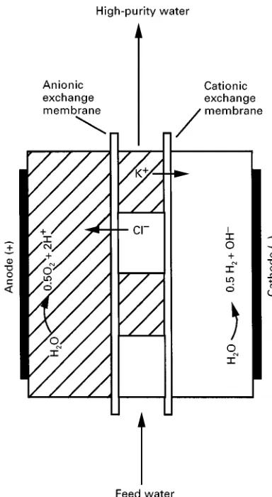
Some materials used in the EIX process are not active electrochemically, that is, they do not contain func-tional groups that can be reduced or oxidized. Exam-ples of commonly used separation techniques of this type include electrodialysisandelectrophoresis/ elec-trochromatography. In electrodialysis, the permselec-tivity of IX membranes is used in combination with an electric Reld to separate anions and cations. In a variation of conventional electrodialysis called elec-trodiaresis polishing, IX materials are packed be-tween the IX membranes; the IX material serves as an immobile electrolyte. The schematic of the process shown in Figure 1 shows that the water is processed through the IX materials. Due to the high concentration of ionic sites in the IX material, fairly resistive (up to 15 M) water can be produced at the outlet. In electrophoresis/electrochromatography where IX packing materials are used, IX inter-actions between the analyte and the column material enhance the separation capability over that available if differences in electrophoretic mobilities alone were used.
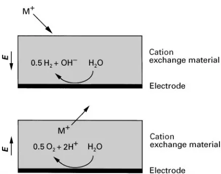
Another process in this category, a process termed EIXby the original researchers (Allenet al.), uses an assembly consisting of an electrochemically inactive IX material attached to an electrode as the separation agent. This approach, for the separation of cations, is shown inFigure 2. (It should be noted that the term
Figure 2 Cation uptake (top) and elution (bottom) at the EIX electrodes. Water reduction leads to production of hydroxyl ions resulting in the de-protonation of sites in the cationic IX resin. In turn, the IX resin will uptake cations to maintain electroneutrality. The electric field,E, present during the water-reduction process, serves to enhance cation transport to/within the cationic IX resin. The reverse reactions occur during cation elution.
Figure 3 (A) Cation intercalation/uptake during film reduction. (B) Cation de-intercalation/elution during film oxidation. (C) Anion intercalation/uptake during film oxidation. (D) Anion de-intercalation/elution during film reduction.
production of hydrogen ions from the splitting of water, which in turn displaces the sorbed cations as in conventional IX processes. In addition, an electric
Reld is generated which accelerates the transport rate
of cations. For anions, anionic IX materials are used; an anodic potential is applied to the assem-bly during uptake and a cathodic potential is applied during elution. The advantages of this approach over conventional IX processes are increased up-take rate due to the applied electric Reld and more efRcient use of hydrogen or hydroxyl ions for both uptake and elution. Although the thermo-dynamics of the elution process have not changed as compared to conventional IX, the close mity of the generated hydrogen or hydroxyl ions to the ex-change sites increases the overall process rate by re-ducing the time required for uptake and elution. In addition, fewer excess hydrogen or hydroxyl ions are required.
EIX Processes Using Electroactive
Ion Exchange Materials
Figure 4 EIX/EaIX columns consist of the EaIX electrodes and counterelectrodes. Connections to the elution solutions are closed during sorption of target ions from the process waste stream. Sorption can be with or without an applied potential (see eqns [2] and [3] in the text). Elution is achieved by applying a potential (see Figure 3B and D) and flowing the elution solution.
for a speciRc cation, then the cation uptake shown in
Figure 3(A) results in the selective separation of a ca-tion, M#1 , from, say M#2 . Elution of M#1 is simply achieved by oxidizing X\back to X, which is neces-sarily accompanied by the expulsion of M#1 (see
Figure 3B). The analogous uptake and elution of an-ions are shown in Figure 3(C) and (D), respectively. For anions, uptake occurs during oxidation, and elu-tion accompanies reducelu-tion. It should be noted that the same sequence of oxidation and reduction is used for the EIX/EaIX approach and the process shown in
Figure 2. More importantly, however, the two ap-proaches are very different with respect to the speciRc electrochemical reactions that take place during oxida-tion and reducoxida-tion. In the process shown inFigure 2, both oxidation and reduction reactions are water-split-ting. The reductive water-splitting results in hydrogen gas and hydroxyl ion production, whereas the oxida-tive water-splitting results in oxygen gas and hydrogen ion production. While this approach results in relative-ly efRcient use of the protons and hydroxyls, the ex-change ratio is not one to one. That is, more than one equivalent of protons is required to displace one equiv-alent of cations (or uptake one equivequiv-alent of anions). In addition, in the processing of radioactive materials, hydrogen gas generation is undesirable because of safety issues. On the other hand, with the use of EaIX materials (as shown in Figure 3A to D), only one equivalent of electrons is needed to elute one equiva-lent of ions. Therefore, using EaIX materials further reduces the amount of secondary waste generated. The electricReld generated within EaIX materials has two functions:Rrstly to increase the transport rate of ions through the EaIX material and secondly to attract (or expel) the ions to the binding sites since the electric
Reld is strongest near an oxidized or reduced site. The last point is particularly noteworthy since it implies that highly selective materials can be used. Although the requirements of high selectivity and ease of elution are typically in conSict, the two requirements are not mutually exclusive if the elution is purely electrostatic in nature.
EaIX materials have been applied for analytical-scale separation in a process called electrochemical chromatography. This process is very similar to con-ventional liquid chromatography except that the sta-tionary phase is electroactive. As in conventional chromatographic processes, the retention times for dif-ferent ions are largely controlled by interactions with the stationary phase. However, the redox state of the stationary phase allows additional control of the inter-actions between the analytes and the stationary phase. For example, anions can be easily separated from cations by applying a positive or anodic potential to the stationary phase. Separation of the different
an-ions, however, still relies on the speciRc interactions between the stationary phase and the ions.
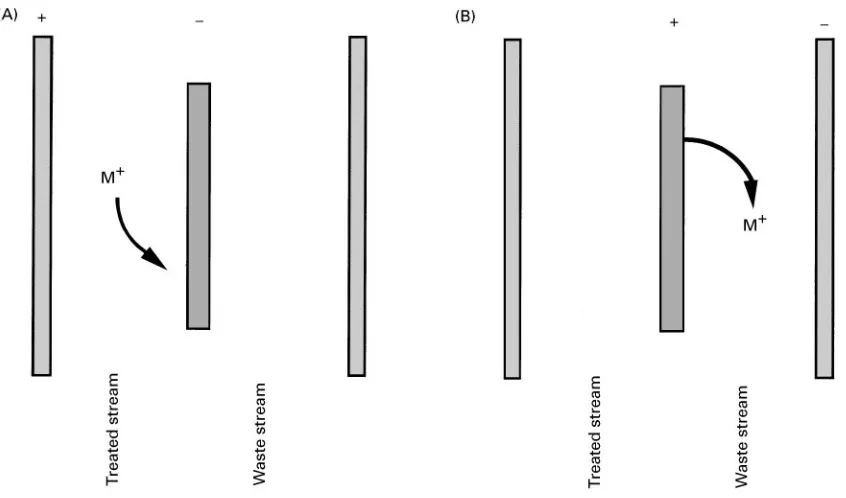
Figure 5 The EaIX membrane is always an electrode when used in the membrane mode. (A) Reduction of EaIX membrane (negative electrode) results in uptake of cations from the treated stream. (B) Oxidation of EaIX membrane (positive electrode) results in elution of cations to the waste stream. The treated and waste streams never come in contact.
Figure 6 Fraction of Na#recovered as a function of K# re-moved for various separation factor,Na
K.
dilute streams since more intimate contact between the process stream and the EaIX materials is possible. In addition, there are possibly more difRculties asso-ciated with preparing EaIX materials as membranes than as packed-bed materials.
Characterization of EaIX Materials
In the development and testing of an EIX/EaIX pro-cess, the ion-loading capacity and speciRc ion selec-tivity of the EaIX materials are of particular interest. Selectivity is deRned in terms of a separation factor2
1, which describes the selectivity for species ‘2’ over species ‘1’:
2 1"
x2/x1 x2/x1
[1]
The numerator is the ratio of ion mole fractions within the EaIX material, and the denominator is the mole fraction (or concentration) ratio in the bulk binary solution contacting the EaIX material. The separation factor is especially useful for estimating process performance. For example, Figure 6 shows the fraction of Na# recovered as a function of K#removed for various values ofK
Na. The plots show that if a minimum of 90% Na#recovery is required while expelling '70% of the K#, then an K
Na of approximately 30 is needed.
Electrochemical Methods
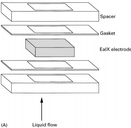
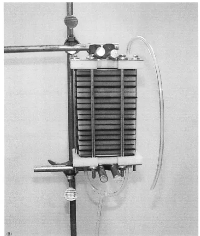
[image:4.568.295.514.526.685.2]Figure 7 (A) Single electrode with the associated spacers and gaskets. (B) Eight-stack cell used for flow-through studies.
the slowly ramped applied potential is less intrusive on the samples. Chronoamperometry, on the other hand, is more suitable for determining the capacity of EaIX materials deposited on a high-surface area elec-trode because mass transfer limitations affect mea-sured cyclic voltammograms (CVs).
A CV is obtained by measuring the current passed at the electrode as the applied potential is swept linearly at a Rxed scan rate between two potential limits. When a suitable potential window is selected, cations (anions) are loaded into the EaIX material during the cathodic (anodic) sweep and the ions are eluted during the reverse sweep. The total charge passes in a load or unload cycle, as determined by integrating the current over any linear sweep, is a di-rect measure of the ion-loading capacity when the charge transfer is only a result of a known electro-chemical reaction (see eqn [2] below). In chronoam-perometry, the potential is stepped from one potential limit to the other. The current is measured while the potential is held at a limit for aRxed period of time, and again, the integrated charge passed is a measure of the ions loaded into or eluted from an EaIX elec-trode assembly.
Electrochemical and Gravimetric Methods
The two electrochemical methods described above yield only the ion-loading capacity. In order to deter-mine the separation factor, an additional independent measurement is required. This is accomplished by combining the electrochemical measurements with gravimetric measurements. A common term for this combined method is electrochemical quartz crystal microgravimetry (EQCM). As the name suggests, mass accumulation within the EaIX material is monitored in addition to the total charge passed. Typically, quartz crystals are coated with an elec-trode on which a layer of an EaIX material is depos-ited. The fundamental frequency of the crystal is very sensitive to the mass loaded in the EaIX material; monitoring this fundamental frequency, the mass loaded during uptake and elution can be determined. For a crystal oscillating at 5.9 MHz, a 1 Hz decrease in the frequency corresponds to a mass increase of
&4.0;10\9g. In EQCM, the oscillation frequency is
monitored at the same time that the potential is swept to obtain a CV. This combination of measurements gives simultaneous information on electrochemical (ion) capacity and mass changes during load and elution cycles. Since mass change differs according to the molecular weight of the ions transported in and out of the EaIX Rlm, the selectivity of the EaIX material for an ion in a binary mixture of known composition can be determined using EQCM. The
analysis is complicated, but not prohibitively, by the simultaneous transport of solvent (e.g., hydration water) and other species with the ions of interest.
Flow Cell Methods
Flow cell methods for EIX/EaIX characterization dif-fer from conventional IX methodologies only in the material preparation. To achieve high volumetric ion-loading capacity, EaIX materials are typically coated on high surface-area electrodes (e.g., porous metal foam or mesh). These EaIX electrodes can be used in any of the modes represented in eqns [2] and [3]. To create an EaIX bed, multiple porous electrodes are used in series (seeFigure 7A and B). When used in the conventional mode in the uptake cycle, the process stream simplySows through the electrodes. The efS u-ent solution composition is analysed and break-through curves are obtained.
Properties of EaIX Materials
Functional requirements of EaIX materials are elec-tronic conductivity, ionic conductivity, selectivity for the ion of interest, and reasonable stability (physical and chemical). Of the numerous inorganic and or-ganic materials that fulRl all or some of the listed requirements, discussions will be limited to nickel hexacyanoferrate (NiHCF) as an example of a cationic EaIX material and polyvinylferrocene (PVF) as an example for an anionic EaIX material.
Figure 7 Continued
particular, are extremely selective for cesium (Cs#) over sodium (Na#) and potassium (K#). More re-cently, the preference of polyvinylferrocene for rhenate (nonradioactive chemical analogue of per-technetate) anions over nitrate anions has been dem-onstrated.
Nickel Hexacyanoferrate
Nickel hexacyanoferrate [NiIIFeII/III(CN)2\/\ 6 ] (NiHCF), an electroactive material, is known to com-plex reversibly with the alkali metal cations such as Na#, K#, and Cs#. Upon reduction of the iron (FeIII)
centre in NiHCF, an alkali cation associates with the ferrocyanide moiety to maintain charge neutrality through the following reaction, where M#is an al-kali metal cation:
MNiIIFeIII(CN)6#M##e\M2NiIIFeII(CN)6 [2]
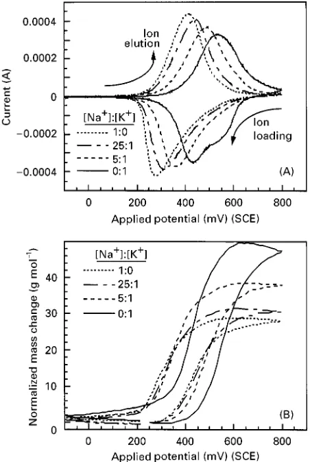
Figure 8 EQCM results for a series of 0.5 mol L\1Na 2SO4and 0.5 mol L\1K2SO4solution mixtures demonstrating selectivity of a NiHCF film for K#over Na#: (A) Cyclic voltammograms indi-cate sensitivity to K#in solutions'25 times more concentrated in Na#; and (B) QCM mass data, normalized by the ion-loading capacity and converted to units of apparent molar weight, indicate greater mass changes as solutions become more concentrated in K#and relatively more K#is loaded into the film. (Adapted, with permission from Rassatet al. (1999), Elsevier Science.)
deintercalation of alkali cations from the Rlm into a contacting solution, while the reduction of depos-ited NiHCFRlm leads to the uptake or intercalation of alkali cations from solution into theRlm (see Fig-ure 3B and A, respectively). The selectivity for alkali cations M# by NiHCF increases with molecular weights, Cs#K#'Na#. Therefore, K# or/and Na#is readily exchanged for Cs#; for example:
Na2NiIIFeII(CN)6#2Cs#Cs2NiIIFeII(CN)6#2Na#
[3]
Equation [3] shows that the EaIX material can be used in conventional IX. The Cs#is bound so strong-ly that elution is onstrong-ly possible through oxidation of the Fe centre from II to III. Chemical oxidation has been demonstrated with NiHCF as well as for the copper and zinc analogues. ApproximatelyRve col-umn volumes of 8 mol L\1nitric acid are required for effective elution of all the sorbed Cs#. The cost and hazard associated with this eluent are signiRcant. Use of the EIX/EaIX approach, therefore, provides an attractive alternative since the oxidation can be done more efRciently via the electrochemical approach.
It is imperative for the EIX/EaIX process that there is intimate contact between the EaIX material and the electronically conducting substrate. NiHCF can be conveniently deposited onto a conducting substrate electrochemically. A nickel surface corroded in a solution containing hexacyanoferrate ions results in the precipitation/deposition of NiHCF on the surface. The electrochemical route is particularly advantage-ous over other methods (e.g., precipitation and sol-gel) since deposition within the pores of a porous electrode can be carried out readily.
Applications The selectivity of NiHCF for alkali cations with an afRnity order Cs#K#'Na# is attributed to the relative sizes of the ions, both hy-drated and not, and the NiHCF cubic lattice structure that the ions must penetrate and then occupy. Be-cause NiHCF is both electronically and ion conduct-ing, is readily deposited as aRlm on conductive elec-trode substrates, and is alkali cation-speciRc, it is an ideal EaIX material for K# and Cs# separation ap-plications.
Potassium separation The forest products industry requires selective removal of K# and recovery of Na#. As the plots in Figure 6 show, the separation factor is critical in determining the extent to which Na#can be recovered for a required removal of K#. Therefore, quantiRcation ofK
Nais essential for scale-up purposes and capital cost estimation. Because
equipment capital costs scale roughly with the elec-trode costs, it is necessary to minimize elecelec-trode area to make the EaIX processRnancially attractive. The larger the separation factorKNa, the smaller the EaIX electrode area necessary to remove a given amount of K#. Electrode area is also reduced if the ion capacity of the EaIX material per unit electrode area is in-creased.
The selectivity of NiHCF for K# in preference to Na# was quantiRed by EQCM and by bulk-contact experiments. Separation factors K
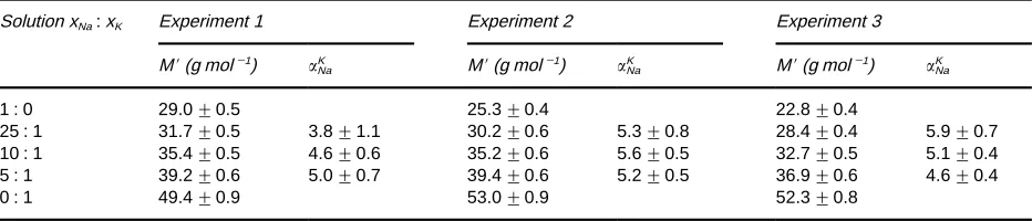
Table 1 Apparent molar masses and separation factors in mixtures of 0.5 mol L\1sodium and potassium sulfate solutions. (Adapted, with permission from Rassatet al. (1999), Elsevier Science)
Solution xNa:xK Experiment 1 Experiment 2 Experiment 3
M(g mol\1) K
Na M(g mol\1) NaK M(g mol\1) KNa
1 : 0 29.0$0.5 25.3$0.4 22.8$0.4
25 : 1 31.7$0.5 3.8$1.1 30.2$0.6 5.3$0.8 28.4$0.4 5.9$0.7
10 : 1 35.4$0.5 4.6$0.6 35.2$0.6 5.6$0.5 32.7$0.5 5.1$0.4
5 : 1 39.2$0.6 5.0$0.7 39.4$0.6 5.2$0.5 36.9$0.6 4.6$0.4
0 : 1 49.4$0.9 53.0$0.9 52.3$0.8
Table 2 NiHCF bulk-contact separation factors and experi-mental conditions. (NiHCF-coated circular disc electrodes
&5-cm diameter by&0.6-cm thick, 80 pores inch\1porosity, and
&60 cm2cm\3specific volume contacted with 18 mL of mixed ion solution)
Test [K#] (mM) [Na#] (mM) Capacity (C) K Na
Initial Final Initial Final
1 2.19 1.30 28.0 29.1 2.06 14
2 0.97 0.30 13.0 13.7 2.31 15
3 4.81 3.44 56.8 54.1 1.97 24
the reversibility of the cation uptake (negative cur-rents) and elution (positive curcur-rents). In addition, the area between the abscissa and either the negative or positive currents is proportional to the net ionic load-ing. Combined with the apparent molar weights shown in Figure 8(B), separation factors ranging from 3.8 to 5.9 were calculated (see Table 1). In addition to providing quantitative estimates of the separation factors,Figure 8(A) and (B) qualitatively show the preference of K# over Na#. As the mix-tures become more concentrated in K#, the peaks shift to higher potential, more in line with that of pure K2SO4 solution. Even in solutions Rve times more concentrated in Na#, the peaks shift substantially toward those for pure K2SO4solution, indicating the relative selectivity of NiHCF for K#. The shift to-wards higher apparent molecular weights in the mix-tures also indicates the preference for K#.
Bulk-contact tests of NiHCF, a more direct measure of selectivity, resulted in separation factors ranging from 14 to 24. Representative experimental details and results are shown in Table 2. In all the tests shown in Table 2, the Na#: K#molar concen-tration ratio was &12, which is the approximate ratio of the ions in pulp mill application. The amount of K# taken up by the NiHCF without any applied potential (IX mode, eqn [3]) was determined from the total solution volume and the difference in K#concentration before and after contact. The
sep-aration factor,KNa, determined by this bulk-contact method, is very sensitive to the total capacity value. Since there are more uncertainties in determining the total capacity for the foam electrodes (in comparison to the small planar EQCM electrodes), the variability and uncertainty of bulk-contact separation factors obtained are greater. Despite the uncertainties asso-ciated with the total capacity, the batch-contact tests are in agreement with the EQCM results in that NiHCF materials are selective for K#over Na#. The reason for the difference in the magnitude of the separation factors determined by the two techniques is presently unclear. Three possibilities are (1) differ-ences in NiHCFRlm preparations resulting from dif-ferences in the electrode substrate on which they were deposited, (2) differences in solution ionic strengths
(&1 mol L\1 alkali for EQCM and (0.1 mol L\1
alkali for bulk contacting), and (3) the potential was applied to NiHCF in the EQCM experiments but not in the bulk-contact tests.
[image:8.568.50.277.630.709.2]Cesium separation The radioactive isotope 137Cs, aRssion product of nuclear fuel processing and cor-rosion of fuel rods in commercial nuclear reactors, is a trace component of several process and waste streams in the nuclear industry. Because of the strong afRnity of NiHCF for Cs#, separation of this ion by EIX/EaIX is ideal. Figure 9(A) and (B) show the EQCM results for dilute Cs# in competition with excess Na#. The experiments are analogous to those described for K# separation above, but the shifts toward pure Cs#solutions observed in the mixtures are more pronounced.
Table 3 summarizes the apparent molar masses and separation factorsCs
Na for a series of Na#: Cs# mixtures. The separation factors range from 178 to 593, clearly demonstrating the enhanced selectivity of NiHCF for Cs#relative to Na#and K#(compare to
Figure 9 EQCM results for a series of 1.0 mol L\1NaNO3and 1.0 mol L\1CsNO3solution mixtures demonstrating selectivity of NiHCF film for Cs#over Na#: (A) cyclic voltammograms indi-cate sensitivity to Cs#in solutions&2400 times more concen-trated in Na#; and (B) QCM mass data, normalized by the ion-loading capacity and converted to units of apparent molar weight, indicate greater mass changes as solutions become more con-centrated in Cs#and relatively more Cs#is loaded into the film.
[image:9.568.291.516.91.192.2](Adapted, with permission from Rassatet al. (1999), Elsevier Science.)
Table 3 Apparent molar masses and separation factors in mixtures of 1.0 mol L\1 sodium and cesium nitrate solutions. Rassatet al. (1999), courtesy of Elsevier Scientific.
Solution xNa:xCs M(g mol\1) CsNa
1 : 0 14.4$0.2
H2390 : 1 31.1$0.9 593$40
H910 : 1 37.3$2.1 341$36
442 : 1 46.1$1.0 268$15
155 : 1 59.3$1.0 178$12
81 : 1 83.0$1.3 361$60
0 : 1 98.4$2.2
HGravimetric and/or electrochemical measurements not at steady state.
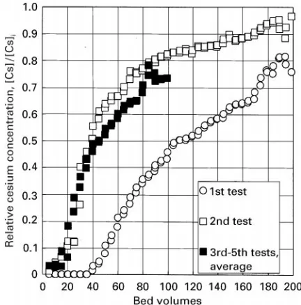
Figure 10 Breakthrough curves for a feed stream of 0.2-ppm Cs in a EaIX bed consisting of eight NiHCF-coated porous nickel foam electrodes operated in IX mode. The electrodes were regen-erated electrochemically in concentrated NaNO3 solution be-tween each test. Experimental conditions: 80 pores inch\1 or
&60 cm2cm\3 nickel foam; CsNO
3 solution flowed at 24 mL min\1; bed volume of&39 mL; and maximum ion capa-city&2.0 C.
In the limited range of K#and Na#mixtures tested, such a trend was not detected.
Flow-through EIX/EaIX experiments demonstrate the regenerability of the EaIX material without the use of highly oxidizing solutions. Breakthrough curves for a 0.2-ppm Cs#feed stream are shown in
Figure 10. Here, the EIX/EaIX system was operated in the conventional IX mode in the uptake cycle. The breakthrough curve for theRrstSow test shows that the breakthrough point (where the concentration of Cs#in the efSuent stream is one-half the feed concen-tration) occurs after&110 bed volumes were passed in the RrstSow test. In subsequentSow tests, each following regeneration of the NiHCF electrodes, the breakthrough capacity was reduced to&40 bed vol-umes and the breakthrough proRles were consistent.
Regeneration cycles were carried out by potential cycling in a solution of sodium nitrate. The reasons for the diminished breakthrough volume after the
[image:9.568.295.511.402.621.2]oxidiz-Figure 11 EQCM results for a series of 0.5 mol L\1NaNO3and 0.5 mol L\1NaReO4solution mixtures demonstrating selectivity of a PVF film for ReO\4 over NO\3: (A) cyclic voltammograms indicate sensitivity to ReO\4 in solutions nine times more concen-trated in NO\3; and (B) QCM frequency shifts indicate greater mass changes as solutions become more concentrated in ReO\4 and relatively more ReO4\is loaded into the film.
ing solutions (i.e., 8 mol L\1nitric acid used by pre-vious researchers).
Polyvinylferrocene
Polyvinylferrocene [!(FeII/III(C5H5) (C5H4CH2 CH2)1#/0)}], or PVF, is a well-studied organometallic polymer. In contrast to NiHCF, oxidation of PVF to the 1#state requires the uptake of anions to main-tain electroneutrality (see Figure 3C), making PVF a suitable anionic EaIX material candidate. Recently, the preference of PVF for perrhenate (ReO\4) over nitrate (NO\3) was demonstrated. The uptake and elution reactions are analogues to that shown in eqn [2]. As with NiHCF, PVF can also be used as conventional IX materials. SpeciRcally, the NO\3 in (PVF#)(NO\3) is readily exchanged for ReO\4. Other possible applications for PVF include the extraction of arsenates and chromates.
PVF has been prepared through chemical, electro-chemical, and plasma polymerization. Both plasma
and electrochemical polymerizations should be suit-able for depositing PVF within porous substrate.
Applications The preference of polyvinylferrocene for perrhenate (nonradioactive chemical analogue of pertechnetate) anions over nitrate anions has been demonstrated. Nitrates are the main competing an-ions for separation of pertechnetate in radioactive tank wastes. The current and the frequency responses of a PVF-coated EQCM as a function of a cyclic potential scan are shown in Figure 11(A) and (B). (The frequency response is shown rather than the normalized mass change because of complications due to the less rigid PVF Rlms compared to the NiHCFRlms.) The more negative (cathodic) potential peaks observed in the pure ReO\4 solution and in the mixture, compared to a pure NO\3 solution, indicate the preference of ReO\4 over NO\3. In addition, the frequency responses shown inFigure 11(B) indicate a substantial mass gained in the PVFRlm upon oxida-tion in a soluoxida-tion containing both NO\3 and ReO\4, more mass than can be attributed to NO\3 alone. This supports the contention that ReO\4 ions (which are heavier than NO\3) are preferentially taken up by the PVF. The data shown inFigure 11(A) and (B) corre-spond to a separation factor of 30.
Future Developments
EIX processes (using EaIX and nonelectroactive IX materials) are very promising methods for ion separ-ation due to the potential savings resulting from minimization of secondary waste generation. Better understanding of system performance through large-scale (e.g., pilot-large-scale) studies still needs to be carried out as well as the development of new materials. For example, EaIX materials selective for strontium (Sr2#) are of interest to the nuclear industry. Calcium (Ca2#) selective materials are valuable for preventing scale formation in many industries. Finally, effective removal of NO\3 and arsenate an-ions is critical for safe drinking water.
See also: II/Ion Exchange: Historical Development; Inor-ganic Ion Exchangers; OrInor-ganic Ion Exchangers; Theory of Ion Exchange.
Further Reading
Genders D and Weinberg NL (eds) (1992)Electrochemistry for a Cleaner Environment. East Amherst, NY: The Electrosynthesis Company Inc.
[image:10.568.49.279.53.382.2]Lewis TM, Wallace GG and Smyth MR (1999) Elec-trofunctional polymers: their role in the development of new analytical systems.Analyst124: 213.
Rassat SD, Sukamto JH, Orth RJ, Lilga MA and Hallen RT (1999) Development of an electrically switched ion exchange process for selective ion separations. Separation and PuriTcation Technology 15: 207.
Rose TL, Rudd E, Murphy O and Conway BE (eds) (1994) Proceedings of the Symposium on Water PuriTcation by Photocatalytic, Photoelectrochemical, and Electro-chemical Processes. Pennington, NJ: The Electro-chemical Society.
Tsuda T (ed.) (1995) Electric Field Applications in Chromatography, Industrial and Chemical Processes. Weinheim: VCH.
ELECTRODIALYSIS: ION EXCHANGE
G. Pourcelly, Laboratory of Materials and Membrane Processes, Montpellier, France Copyright^ 2000 Academic Press
Introduction
Separations with synthetic membranes have become increasingly important; today membrane processes are used in a wide range of applications and their number will certainly increase.
A membrane is a permselective polymer, inorganic or metal phase which restricts the motion of certain species. By controlling the relative rates of transport of various species it gives one product depleted in certain components and a second product concen-trated in these components. Membrane performance is characterized by two terms: Sux and selectivity. Flux (or permeation rate) is the volumetric massSow ofSuid passing through the membrane per unit area of membrane and unit mass time. Selectivity is a measure of the relative permeation rates of different components through the membrane.
Processes may be classiRed according to the driving force used: (1) a pressure differential leads to micro-, ultra- and nanoRltration and reverse osmosis; (2) a concentration difference across the membrane leads to diffusion of a species between two solutions (dialy-sis); (3) a potential Reld applied to an ion exchange membrane leads to migration of ions through the membrane (electrodialysis, membrane electrolysis and electrochemical devices). This last category and more speciRcally electrodialysis is the subject of this section. This electrically driven process uses ion ex-change membranes, a description of which follows.
Ion Exchange Membranes
Electrodialysis (ED) uses membranes containingRxed charged groups attached to the polymer backbone of its membrane. Two kinds of ion exchange mem-branes (IEMs) are used in ED:homopolar membranes
bearing Rxed charges of the same sign and bipolar membranes bearing positive and negative Rxed charges located on each side of the membrane.
IEMs are sheet-shaped materials through which a selective ion transport can be established under a driving force, generally an electricReld and/or a con-centration gradient.
Most of them are of a polymeric nature. They are constituted of reticulated macromolecular chains forming a tridimensional structure. In this network, ionizable functionalized groups are attached to the polymeric matrix and are at the origin of the brane selectivity. For example cation exchange mem-branes (CEMs) contain Rxed negative charges and mobile cations which can be exchanged with other cations present in an external phase in contact with the membrane. The ions balancing theRxed exchange sites are called counterions. The concentration of counterions is relatively high and therefore counter-ions carry most of the electric current through the membrane. TheRxed charges attached to the polymer matrix repel ions of the same charges (co-ions). This exclusion, which is a result of electrostatic repulsion, is called Donnan exclusion, named after F. G. Don-nan, who Rrst reported the phenomenon in 1910. However, as the membrane selectivity is never ideal, the membrane material can be penetrated by a non-negligible amount of electrolyte. A schematic structure of such a homopolar CEM is depicted in
Figure 1. Under an applied electric Reld, the CEM bearing sulfonic exchange groups (}SO\3) mainly allows the transport of counterions.