j/\-
3000
/-:" r
~t)
LIMITED WARRANTYMindset Corporation ("Mindset") warrants the product it manufactures for a period of six (6) months from the date of
purchase. During the warranty period,
Mindset at its option will repair or replace components that prove to be defective at no charge provided the
prcc~ct is returned to a Mindset dealer.
This warranty does not apply if, in the opinion of Mindset, the product has been damaged by accident, misuse, misapplica-tion, or as a result of service or
modification by other~than a Mindset
dealer.
NO OTHER WARRANTIES ARE EXPRESS OR
IMPLIED, INCLUDING, BUT NOT LIMITED TO, THE IMPLIED WARRANTIES OF
MERCHANTABILITY AND FITNESS FOR A
PARTICULAR PURPOSE. ANY IMPLIED
WARP~~TIES ARE LIMITED IN DURATION TO
THE >IARRANTY PERIOD SET FORTH ABOVE. IN
NO E-TENT SHALL MINDSET BE LIABLE FOR LOST PROFITS, LOSS OF GOODWILL, OR ANY OTHER SPECIAL OR CONSEQUENTIAL DAMAGES.
This warranty gives you specific legal
rights. You may also have other rights,
FEDERAL COMMUNICATIONS COMMISSION RADIO FREQUENCY INTERFERENCE STATEMENT
WARNING: This equipment generates,
uses, and can radiate radio frequency energy and, if not installed and used in accordance with the instructions manual, may cause interference to radio
communi-cations. It has been tested and found
to comply with the limits for a Class A
computing device pursuant to Subpart J
of Part 15 of FCC Rules, which are designed to provide reasonable pro-tection against such interference when operated in a commercial
environ-ment. Operation of this equipment in a
residential area is likely to cause
interference, in which case the user, at his own expense, will be required to take whatever measures 'may be required to correct the interference.
The information in this guide is subject to change; these changes will be incor-porated in later editions of this guide.
MINDSET is a trademark of Mindset Corporation.
Copyright 1987, Mindset Corporation.
All rights r~served.
206000-001
Printed in U.S.A.
TABLE OF CONTENTS
INTRODUCTION
SE~TING UP THE SYSTEM
Identifying System Components Plugging In Your System
Setting Up The Keyboard
Identifying Front Panel Adjustments &
Controls
Identifying Back Panel Connectors ,System Setup in Video Environments
Disk Drives
TROUBLESHOOTING
Diagnosing Your Problem
The Amber LED Doesn't Light on Power-Up The System Does Not Operate
No Picture on the Display No Response to Keyboard Input ON/OFF Switch Has No Effect The Disk Drives Do Not Operate The System Can't Read or Write to a
OPERATION GUIDE
Appendix I Application Notes
Appendix II Floppy Disk Drive
Appendix III Specifications
Appendix IV Drawing Devices
M-3000 User's Guide 2
Operation
OPERATION GUIDE
INTRODUCTION
This OPERATION GUIDE has been designed to help you start working with your
Mindset M-3000 System. It is strongly
recommended that you read through this short guide before you start using the
system. The guide will help you
identify system components, connect the components properly, and power up the
system. It also provides general
instructions for using software.
SETTING UP THE SYSTEM
IDENTIFYING SYSTEM COMPONENTS
Before you connect any of your
components, check to ensure that.you have received each of the followlng
items:
Main Unit:
Keyboard:
Mouse:
included with the Main unit is this Operation Guide and a six foot AC cord for connecting the unit to an AC outlet (110V/60Hz).
included with the Key-board is a cQiled cable
for connecting the Key-board to the Main Unit.
included separately for connecting to the
keyboard.
PLUGGING IN YOUR SYSTEM
The Mindset M-3000 has been designed to be either table-top mounted or mounted
in a standard 19" rack (using the
optional Mindset rack mounting shelf). The following considerations should be kept in mind when deciding how and where to place your system:
4
1. The system should be placed on a
level surface ensuring that the ventilation holes on the under-side of the Main Unit and the fan exhaust at the back are not
obstructed.
2. Locate your system near a power
outlet. Do not use a switched AC
outlet since this could result in the unit being inadvertantly
switched off while it is in use. Switching On and Off should only' be done by using the illuminated power On/Off switch on the front of the Main Unit.
3. The Main Unit comes with a
separate power cord which plugs
into the rear of the unit. After
you have located a place for your system, plug the power cord into the Main Unit, then into the outlet.
SETTING UP THE KEYBOARD
The keyboard is designed to be connected to the Main Unit directly by a cable. To attach the keyboard, locate the
coiled keyboard cable. Then find the
keyboard cable connector at the left corner of the keyboard, and insert one
OPERATION GUIDE
end of the cable into this connector. (Because the connectors on both ends of the cable are identical, it doesn't
matter which end of the cable you attach
first.) Attach the other end of the
cable to the Main Unit by plugging it into the socket in the lower left corner of the Main Unit.
CAUTION: The keyboard must be connected
to the Main Unit with the special
Mindset coiled keyboard cable. DO NOT
USE A STANDARD TELEPHONE CABLE!
Insert the other end of the cable into the keyboard connector at the left side
of the Main Unit. Figure 2-1 shows the
proper attachment of the keyboard to the Main Unit.
... """"'",...,. '1'''' _ _ _ ' _ t""! ... ..: ~~
OPERATION GUIDE
M-3000 User's Guide 7
IX:
~§
mw
~~
o
IDENTIFYING FRONT-PANEL CONTROLS
Figure 2-2 shows the front panel controls.
Input Source Select Push Button
When this switch is in the IIINIl
position, the input video source is
taken from the Component In connector at
the back of the Main Unit. The unit
ex-pects the video to be in Y, R-Y, B-Y format, and processes it accordingly.
When the Source Select switch is in the
IIOUT II position, th~ Main unit takes
its video from the-~--NTSC In connector.
This input is for NTSC IV p-p composite
video. Put the switch in the lIout"
position when using the M--3000 upstream
from a switcher. The NTSC In connector
is then used as Sync In.
The following adjustments should be made
only by a qualified technician with .uitable test equipment (i.e., waveform analyzer, vectorscope, etc.).
M-3000 User's Guide 8
IMPORTANT
Mindset M-3000 Manual Addendum
The following information is new or updated since the M-3000 Operations Guide was printed.
HARD DISK PARK---CAUTION
Every time the M-3000 is to be moved from one location to another or to be shipped, the hard disk heads MUST be
"parked.1I
This protects the heads and the data on your hard disk from any possible damage that can be caused by mechanical shocks to the system during
shipment. A function has been added
to the M-3000 Main Menu to park the
hard disk. This function MUST be
performed as the LAST thing you do before turning off the M-3000 and preparing it for transport.
INTERNAL/EXTERNAL SYNC SWITCH
The sync switch on the rear panel of the M-3000 (between the AC line socket and the 'Component Inl connector)
allows the user to operate the M-3000 in two distinct modes, depending on whether or not an external sync source
(ie., camera, VTR, black burst, etc.) is present on the 'NTSC IN' connector.
INTERNAL SYNC
With the switch in the UP position .
(INT~, the M-3000 will generate its
own 1nternal 3.58 MHz subcarrier and should not have any cable connected tc
the 'NTSC IN ' connector. This means
~hat the M-3000 in this configuration
1S not able to genlock to a video source and therefore must be used upstream of any other video equipment. The other video equipment will then genlock to the video output of the
M-3000. This mode would normally onll
be used if the operator wants to use the M-3000 in an off-line stand alone set-up or when a sync source may not be available •.
EXTERNAL SYNC
With the switch in the DOWN position (EXT), the M-3000 is in the external sync mode and requires a sync source to be present at the 'NTSC IN'
connector for proper operation. In
this mode the M-3000 genlocks to the external sync source and can then be used upstream or downstream of other video equipment such as a switcher. Using the M-3000 in an on-line mode is
the most common setup. When used in
-2-the external sync mode and -2-the sync is lost (eg., a VTR is the sync source and it is stopped or shuttle-searched) the M-3000 will (until sync is
restored) drop out of genlock.
NOTE: Once you have set-up the M-3000 with your video equipment to be either
internally or externally synced, the switch position should not be changed unless you also change your video
equipment set-up. When switching
between internal and-external m~es,
POWEROFF--your"sy~j:~-:--·
... -.-.... ---.
---~ "
KEY OUT SIGNAL
The key out connector from the back panel of the M-3000 is a chroma key signal of 0.7 volt p-p when terminated
into a 75 ohm load. The signal is 0.7
volt when the key is on (ie.,
displaying external video source) and at 0.0 volt when the key is off (ie., displaying M-3000 graphics).
KEY DELAY CONTROL
The values of the key delay controls on the front panel of the M-3000 have
changed. The coarse adjustment is ten
steps of 50ns per step and the fine adjustment is ten steps of 5ns per step.
-3-SOFTWARE BACK-UP DISK PACKAGE
All the software for the M-3000 is already installed on the hard disk
at the factory. In most instances
you will never have to worry about' installing software onto your hard
disk. However, if you cannot load a
p~rticular program from your hard
d1sk, you may need to re-install all software.
A package of diskettes with
instructions is included with your
M-3000. These are the BACK-UP DISKS
to the applications and data files that were ALREADY INSTALLED on your
hard disk at the factory. Put these
disks away in a safe place. DO NOT
USE THESE DISKS except as directed in the instructions provided with them.
-4-INTRODUCTION
The purpose of this section is to
provide a quick and easy way to set up and make sure your M-3000 system is
working properly. PLEASE REFER TO THE
OPERATION GUIDE SECTION OF THIS MANUAL FOR MORE DETAILS ON SYSTEM SETUP AND OPERATION IN DIFFERENT VIDEO
ENVIRONMENTS. The OPERATION GUIDE
contains helpful hints and illustrations and contains a detailed troubleshooting section.
SYSTEM ELEMENTS
You will find the following items
packed with your Mindset M-3000 System:
o M-3000 System Unit
o Keyboard and cable
o A.C. cord
o Mindset Mouse
o M-3000 Operation Guide (this manual)
If any of these items are missing, contact your Mindset Dealer where you purchased this system.
You must minimally provide the following equipment:
o Composite or Analog RGB monitor
o All BNC cables to connect the M-3000 to
SETUP
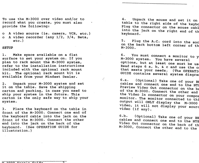
To use the M-3000 over video and/or to record what you create, you must also provide the following:
o A video source (ie. camera, VCR, etc.)
o A video recorder (any 1/2, 3/4, Beta,
etc.)
SETUP
1. Make space available on a flat
surface to set your system on. If you plan to rack mount the M-3000 system, refer to the installation instructions included with the optional rack mount
kit. The optional rack mount kit is
available from your Mindset Dealer.
2. Unpack your M-3000 system and set
it on the table. Save the shipping
carton and packing, in case you need to ship your system in the future. This carton is the only safe way to ship your system.
3. Place the keyboard on the table in
front of the M-3000. Connect one end of the keyboard cable into the jack on the front of the M-3000. Connect the other end into the jack on the back of the
keyboard. (See OPERATION GUIDE for
illustration.)
M-3000 Userls Guide 2
SETUP
4. Unpack the mouse and set it on the
table to the right side of the keyboard. Plug the connector on the mouse cable into the jack on the right end of the keyboard.
5. Plug the A.C. cord into the socket
on the back bottom left corner of the M-3000.
6. You must connect a monitor to your
M-3000 system. You have several
options, but at least one must be used.
Read steps 6 a, b, & c and use the one
that meets your needs. (The OPERATION
GUIDE contains several system diagrams.)
6.a. (Optional) Take one of your BNC
cables and connect one end to the NTSC Preview Video Out connector on the back
of the M-3000. Connect the other end to
the Video In connector on your composite monitor. The monitor connected to this output will ONLY display the M-3000 video, it will not display your source video (if any).
6.b. (Optional) Take one of your BNC
cables and connect one end to the NTSC Video Out connector on the back of the M-3000, Connect the other end to the
[image:10.802.81.743.43.586.2]Video In connector on your video
recorder. Connect a composite monitor to the Video Out jack on your recorder.You may connect a composite monitor directly' to the M-3000 instead of a recorder.
G.c. (Optional) If you have an Analog
RGB monitor you can connect it to your M-3000 in addition to or instead of your composite monitor. Take four of your BNC cables and connect each to the R, G, B, and SYNC outputs on the back of the M-3000, and the other ends to their respective inputs on your Analog RGB monitor.
7. (Optional) Connect the BNC cable
from your video source to the NTSC Video In connector on the back of the M-3000.
8. Remove the floppy disk head
protector by turning the lever on the drive counter clockwise until it is
horizontal. Remove the cardboard insert. Keep this insert in case you need to transport the M-3000 in the future.
9. Make sure the power switch is in
the off (down) position. Plug the A.C. cord into a wall or power strip outlet.
10. Put the Source Selector Switch (on
the front of the M-3000) in the NTSC posi tion. Slide the Fade Bar all t·he way to the left.
M-3000 User's Guide 4
11. Turn on your video source(if any)
and monitor(s). If your source is a tape deck, playa tape.
12. Turn the Power Switch (on the front
of the M-3000) ON. The amber light on
the switch will turn on.
13. The M-3000 will now complete its
power up diagnostics, and when its done, the M-3000 will display the MAIN MENU.
You have successfully set up your Mindset M-3000System. You can now go
to the Tutorial section of this manual to become familiar with each of the
M-3000's applications. Before you ~
permanently set up and use your M-30·00 on a daily basis, you should at least become familiar with the OPERATION, MAIN MENU, and TUTORIAL sections of this manual.
If you do not see the MAIN MENU on your monitor do the following:
Check that each piece of'equipment you
are using is plugged in and powered on.
Check that the BNC cables are connected properly and in working order.
SETUP
Follow each of the set-up steps again to see if there was any thing you missed.
If you are still having difficulties, please refer to the Troubleshooting Section of the OPERATION GUIDE, or contact your Mindset Dealer or Mindset Corporation'for further help.
M-3000 User's Guide 6
~ U) Q Q a: « l:
OPERATION GUIDE
~
..
III
en
e eC e C") Z :&
2
.-- I
--
-ICo --,
T
/[W]
~tr
8
0
0
0
0
0
[Q]
a:§
WW ..Jz CDZ «0 00 / z OJ: a:~ w-;=3: 0U) Q. w z u:: ~~ .... a:~g
> ( , )
w~~
~..Ic(
IW::C
C Q. > ....
W j!
~zw
l°l:
NLLa:
a:OY:! ::ca::
I~
m :;:) enI
I
~C~ wzz.... c(~ ,
w(,)o
"'-
U)U)Q. I-~:& :;:)20 Q. ..J w· z ~ ~ z o a: u.. o o ow C")
~ ::i
g
(J a: wa:
a: ~ m:::»
en
Subcarrier Phase Adjustment (Coarse and
Fine)
The two knobs immediately to the right of the Input Select Switch are for
Subcarrier Phase Adjustment. The left
knob is for coarse adjustments and has
four positions: 0-90, 90-180, 180-270,
and 270-360 degrees. The other
sub-carrier knob is for fine adjustment of the phase within the range set by the coarse knob.
The Subcarrier Phase Adjustment is used to change the phase of the subcarrier
with respect to sync. (This is not to
be confused with Hue Adjustment.) The
RS170A specification states tha~ t~e
phase of subcarrier should be wlthln +30 degrees of the. rising edge of sync, but the phase may need to be adjusted outside these limits in order to match some other piece of video equipment which itself is not within the RS170A
specification. In a basic se~up with an
M-3000 and a monitor, there wlll be no observable effect on the screen of adjusting the subcarrier phase.
When the unit leaves the factory, the phase is set within the limits imposed by E.I.A. RS170A, and the coarse and
fine adjustment knobs are both. positioned fully counterclockwlse.
M-3000 User's Guide 10
Horizontal Phase Adjustment
The middle knob is for the adjustment of
the Horizontal Phase. The range is
+/-3us.
The adjustment of the Horizontal Sync Phase is to allow the user to compensate for delays in his system due to such things as long runs of cable, other
equipment in the line, etc. Horizontal
phase is factory preset to be O~s when
the white mark on the knob is in the "12 o'clock" position.
Key Delay Adjustment
The two rightmost knobs are for the key
delay, the left one b~ing~the coarse
adjustment and the right being the fine
adjustment. There are ten steps on each
knob giving precise control of the key delay.
The M-3000 can be used either "upstream"
or. "downstream" of a switcher. In a
"downstream" configuration, the key
delay is not necessary. The key delay
switches should be left in their factory preset position, each knob fully
counterclockwise. However, if the
M-3000 is used "upstream" of a switcher,
OPERATION GUIDE
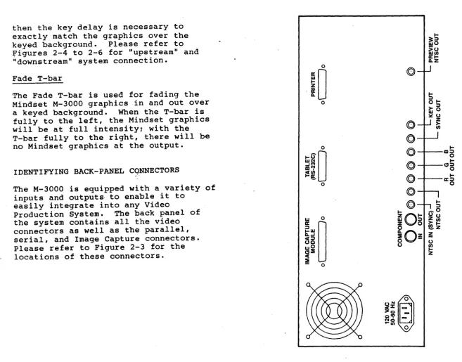
then the key delay is necessary to exactly match the graphics over the
keyed background. Please refer to
figures 2-4 to 2-6 for "upstream" and "downstream" system connection.
Fade T-bar
The Fade T-bar is used for fading the Mindset M-3000 graphics in and out over
a keyed background. When the T-bar is
fully to the left, the Mindset graphics will be at full intensity: with the T-bar fully to the right, there will be no Mindset graphics at the output.
IDENTIFYING BACK-PANEL CQNNECTORS
The M-3000 is equipped with a variety of inputs and outputs· to enable it to
easily integrate into any Video
Production System. The back panel of
the system contains all the video connectors as well as the parallel, serial, and Image Capture connectors. Please refer to Figure 2-3 for the locations of these connectors.
M-3000 User's Guide 12
OPERATION GUIDE
M-3000 User's Guide
IZ O I
-W :l
Z 0
o
~Oz
o
-o
I-3:::l wO
>0
We/)
Irl-Q.Z
I-:::;,
01->::l
wO
~o Z
>
e/)
I-:l
_ 0 0 0
Z e / )
>1-~Z
~ o
~
Z
[image:14.803.69.726.58.572.2]CONNECTORS
AC CORD
COMPONENT IN
COMPONENT OUT
NTSC IN (SYNC)
NTSC OUT
R, G, B
Provides power to the system.
For incoming Compo-nent video (Y, R-Y, B-Y) •
Provides Component video output (Y, R-Y, B-Y) •
For incoming NTSC composite video (IV p-p). [If the M-3000 is being used upstream without an NTSC video
feed, then in order to synchronize the unit to the other equipment downstream, a black-burst or sync pulse must be connected to
this input.]
Provides NTSC composite video output (IV p-p).
Provides the Red, Green, and Blue component video outputs.
M-3000 User's Guide 14
SYNC OUT Provides the sync
necessary for the RGB color signals.
KEY OUT Provides the delayed
key signal output.
PREVIEW NTSC Provides a lower
OUT quality NTSC video
output that can be used for previewing graphics appearing at the NTSC OUT output.
(The output from this connector should not be
r~corded: recording is
done from the NTSC OUT connector.)
IMAGE CAPTURE Conn'ector for the
MODULE optional M-3000
Image Capture Module.
TABLET(RS-232C) Serial I/O Connector
for external devices that communicate over a serial line, for example, a graphics tablet.
PRINTER Connector for printers
with a standard
parallel interface. Use a standard IBM com-patible printer cable for connection.
OPERATION GUIDE
SYSTEM SETUP IN VIDEO ENVIRONMENTS
The M-3000 is quite flexible and can be used in a variety of different video environments---from simple to
sophisticated. It offers professional quality performance in both upstream and downstream installations.
DOWNSTREAM OPERATION
The video circuits in the M-3000 process the signal at the "CAVil (Component
Analog Video) level. In a downstream
installation, the M-3000 does all of ~he
mixing and keying. The M-3000 may be used in a simple downstream system with
a single vi~eo input, edit controller,
and record VTR as in Figure 2-4. The M-3000 can be placed between the output of a source VCR and the recorder in an editing system. Of course, in the
simplest configuration all that's needed is a video source, the M-3000, a record deck, and an online monitor.
M-3000 User's Guide 16
OPERATION GUIDE
M-3000 User's Guide
ONAS
B
~no OS~N
M31A3Yd
~no :)S~N
NIOS~N
17
z
o
fi
a: w
a.
o
:i
c:(
w a:
t;
z
~
c
W
..J
a.
:i
In a more elaborate system, the M-3000 can be placed after the output of the switcher or special effects generator as in Figure 2-5.
In all downstream situations the user
gains the advantage of the M-3000's compon. mixing without having to purchase a componl
special effects generator. If the incominl
signal is NTSC, the M-3000 "decodes II it anc
produces a CAV signal which can be mixed w:
the graphics. The M-3000 then provides
either a component or NTSC output of the
mixed signals. Even when an NTSC output i:
used, the result is a signal with greatly reduced edge effects or chroma crawl and noise.
M-3000 Userls Guide 18
~
!!!->
WI-.
f8
M-3000 User's Guide
ONAS
a
1.no OS.LN
M31A3~d
NI (03011\)
:lNJ1
l.n0 OS.LN
NIOS.LN
19
z
o
~
a:
w
Q.
o
:IE
<t
w
a:
I-en
z
3:
o
)
OPERATION GUIDE
UPSTREAM OPERATION
In a typical upstream system, the M-3000 can provide a key signal and either
component or composite video sign~ls to
a special effects generator or sWltcher. There are front panel controls to adjust
SC phase, H-phase, and key dela~ •. The
key delay control reduces or ellmlnates the need for external delay lines. In an upstream installation, the user's S.E.G. (special effects generator) does all the keying and mixing of the M-3000's
signals with the video source. The
quality of the key depends largely upon the quality of the S.E.G. and type of
s~:gnal being used (CAV or NTSC). If. a
component S.E.G. is used, the resultlng quality should be much better.
Figure 2-6 shows the M-3000 in a typical upstream environment.
DISK DRIVES
The M-3000 contains a 20 megabyte hard disk drive. This make program loading much faster and easier, and leaves plenty of room to store hundreds of picture images, and thousands of pages
of text. The hard disk drive is
automatically powered on when the Main
unit is turned on. All of the character
generatioh, logo creation and paint, and
M-3000 User's Guide 20
OPERATION GUIDE
animation and effects software is
installed on the hard disk, as well as multiple font sets.
When the Main Unit is initially powered on, the MAIN MENU will be displayed on
the screen after about a minute. This
menu allows you to load and operate all of the M-3000's programs from the hard disk, to load an external program from the floppy disk drive, or do some
special functions. Please refer to the
MAIN MENU section of this manual.
The M-3000 also includes a single 5
1/4-inch floppy disk drive. For
information on floppy disk operation please refer to APPENDIX II at the back of this section.
AV130 .... ----~~:-:=:1
A3>1 AV130 A3>1
HI.
3~t:lnOS .1no ~S.1H
M-3000 User's Guide 22
TROUBLESHOOTING
With proper care and handling, your system should give you trouble-free
operation. However, when problems do
occur, you can use the procedures below to identify many of the sources of the problems yourself.
DIAGNOSING YOUR PROBLEMS
The following section lists some of the
problems that may occur. Try all the
suggestions listed before you contact your dealer or Mindset for assistance.
THE ORANGE "POWER-ON" LAMP IN SWITCH DOESN'T LIGHT ON POWER-UP
1. Check that you plugged th'e power
cord on the Main Unit into a working wall unit.
THE SYSTEM DOES NOT OPERATE
1. If nothing appears on the screen
when you turn the Main Unit on, unplug the Main Unit from the AC outlet and wait 5 to 10 seconds before plugging the system in again.
OPERATION GUIDE
2. Check that you turned the Main
Unit ON.
3. Make sure that the power cord
from the Main Unit is plugged into a working power outlet.
4. Ensure that you have properly
connected your display monitor to your Main unit.
NO PICTURE ON THE DISPLAY
1. Check the display power cord.
2. Check that the Main Unit power
cord is plugged in and that the keyboard cable has been properly connected •.
3. Ensure that the ON/OFF switch is
ON.
4. Check for proper connection of
the display monitor.
NO RESPONSE TO KEYBOARD INPUT
1. Check your keyboard for the
proper connections to your Main Unit.
M-3000 Userls Guide 24
OPERATION GUIDE
THE FLOPPY DISK DRIVE DOES NOT OPERATE
1. Make sure that you have correctly
inserted the diskette into the disk drive slot and returned the lever on the front of the disk drive to the closed position (see Appendix II, "Disk Drive
Operation," for information about inserting and removing
diskettes).
THE SYSTEM CANIT READ OR WRITE TO THE FLOPPY DISK
1. Make sure that the lever on the
front of the disk drive is in the closed position.
2. Check that the diskette you are
using is not write-protected, copy the information on that diskette to another diskette and use the second diskette.
If,
at this point, you are s t i l lexperiencing system problems:
o TURN OFF AND UNPLUG YOUR SYSTEM.
o DISCONNECT ALL CABLES.
o START OVER FROM THE BEGINNING OF
SYSTEM SETUP.
o FOLLOW EACH STEP CAREFULLY!
APPENDIX I
APPLICATION NOTES
1. Interlaced and Non-Interlaced Modes
The Mindset M-3000 can be set in either interlaced or non-interlaced mode,
depending on the application required by
the user. In video applications where
the NTSC signal is required, the Mindset M-3000 should be set in the interlaced
mode. It is either automatic or
adjustable within the software
application. Refer to each software
package for instructions. Examples of
such video applications are time base
correction, production switchi~g, video
processing, and video recording.
2. RS-l70 and RS-170A Signals
When the Mindset M-3000 is placed in the interlaced mode, it generates an RS-l70A NTSC signal from the Composite Video Out
connector. However, when the Mindset
M-3000 is used in genlocking applica-cations, the output tracks the sync of
the incoming external video signal. If
the incoming external video signal is RS-l70A, the output from the M-3000 is RS-l70A.
M-3000 User's Guide 26
3. Dithered Colors
The use of dithered colors* on a composite video monitor IS NOT
RECOMMENDED. Dithered colors will cause
severe interference in the chroma
channel, which will be seen as flicker on the screen in the areas where the
dithered colors were used. A similar
situation will occur when a single pixel
is being displayed. To avoid excessive
chroma crawl (an apparent motion of the pixels on the boundary between two color transitions), the color transitions
should be designed very carefully. The
chroma crawl can be minimized by using less saturated colors and proper hue
selection for the color t~ansitions.
(*Dithered colors are colors produced by creating a checkerboard pattern with two
different colors. For example, pink can
be produced by a fine checkerboard pattern of red and white.)
4. IIChainingl l
Two Mindsets
It is possible to genlock any Mindset
System to a Mindset M-3000. In such a
case, the composite video output of one Mindset is used as an external video
source for the Mindset M-3000. It is
very important that the Mindset System being used as a video source be set in
the interlaced mode. Otherwise,
OPERATION GUIDE
5. Absence of External Video
In the absence of external video being connected to the M-3000, the unit has
the ability to generat~ its own 3.58M~z
subcarrier which is then used to prov1de an RSl70A NTSC video signal, available at the NTSC OUT connector.
M-3000 User's Guide 28
OPERATION GUIDE
APPENDIX II
FLOPPY DISK DRIVE OPERATION
HOW YOUR SYSTEM USES DISKETTES
A diskette is a 5 1/4-inch diameter magnetic recording disk enclosed in a
protective cover. The disk drive places
information on a diskette in a pattern of concentric circles divided into
sections called sectors. Each
concen-tric circle is called a track.
The magnetic heads of the disk drive "read" the tracks as the diskette spins
in the drive. One magnetic head reads
and records information on the top side of the diskette and the other head reads and records on the bottom side •
. SELECTING THE PROPER DISKETTES
The Mindset M-3000 accepts
soft-sectored, double-sided, double-density diskettes.
LOOKING AT A DISKETTE
A diskette is contained in a protective cover (1 in Figure A).
A Diskette
There are several exposed areas that
you can see on this cover. One area is
the surface around the large hole in the center of the diskette (2 in Figure A). This hole is called the spindle hole because the spindle of the disk drive
fits into it to spin the disk in the drive.
Another area is the head-slot (3 in
Figure A). The head-slot area provides
access for the magnetic head of the disk drive as the diskette spins inside the cover.
Other important areas of the diskette are the write-protect notch and the
label. When covered with foil tape, the
write-protect notch (S in Figure A)
prevents the writing of data onto the
diskette. Your computer can still read
what's on the diskette but it can't
write anything on it. Covering the
write-protect notch ensures that your
computer doesn't replace valuable .
information on your diskette with new
information. You may want to cover the
write-protect notch on diskettes that you don't expect to change.
The label in the upper left corner of the diskette (6 in Figure A) is a
manufacturer's label. To help you
identify what is on your diskette, affix a temporary label next to the
OPERATION GUIDE
turer's label, and write on the label a
description of the diskette con~ents.
This way, you always know what.ls on
each diskette. To avoid damaglng the
diskette's surface, be sure to use a felt-tipped pen when writing on the
label. Do not press hard.
Diskettes are stored in
static-resistant envelopes (7 in Figure A).
The envelopes protect the exposed areas of the diskette.
OPERATION GUIDE
CARING FOR YOUR DISKETTES
To avoid frustration and extra work, follow these guidelines in caring for
your dis~ettes:
1. Always use a felt-tipped pen when
writing on a label affixed to the protective cover.
2. Do not touch the head-slot area,
spindle hole, or sector hole. These areas are sensitive to dust, scratches, and finger-prints.
3. Keep your diskettes' away from
metallic objects such as magnets, tape recorders, and
headphones. These objects may
cause distortion or erasure of your stored data.
4. When not using them, store your
diskettes in an upright position
in their envelopes. Position
the label at the top so that you can easily identify each diskette Diskettes usually come packaged
in stand-up boxes. These boxes
make excellent storage containers for your diskettes and their
envelopes.
5. Do not store your diskettes in locations'subject to extreme temperatures.
INSERTING AND REMOVING DISKETTES
To insert a diskette into a disk drive slot, follow these five steps:
1. Carefully ~emove the diskette
from the protective envelope.
2. position the diskette so that the label side is up and toward you. Face the head-slot notch toward the Expansion unit.
3. Insert the diskette into the slot <until it stops.
4. Turn the lever on the front of the disk drive clockwise
90 degrees to close the drive. To remove a diskette, turn the lever on the front of the disk drive counterclockwise 90 degrees and pull the diskette out of the
drive. Return your diskette to
its protective envelope for storage.
NOTE: Do not remove a diskette when the
red activity LED is on.
... A
BACKING UP INFORMATION STORED ON DISKETTES
Earlier in this section, you learned that you can save important information on your diskette by covering the
write-protect notch with foil tape. Another
way to protect information is to "back up" your diskette.
When you back up your diskette, you make
another copy of it. This second
diskette contains everything the
original diskette contains. Backing up,
therefore, ensures that you always have another copy of your important programs or data.
To back up your diskettes you do need to
use a diskette copy routine. This
routine is sometimes provided as part of
your applications program. Most of the
MINDSET software allows you to back up on a diskette or the hard disk.
OPERATION GUIDE
APPENDIX III
SPECIFICATIONS
PHYSICAL CHARACTERISTICS
Main Unit
Width Depth Height Weight
Keyboard
Width Depth Height Weight Angle of
17.5 inches (445mm) 14.0 inches (356mm) 7.0 inches (178mm)
Approx. 30 pounds (13.6Kg)
16.0 inches (407mm) 7.0 inches (178mm) 2.0 inches ( Slmm)
Approx. 3 pounds (1.4Kg)
inclination Total Shipping Weight
9.0 degrees
Approx. 33 pounds (15Kg)
Electrical Inputs:
Composite Video Sync. (NTSC)
Component Video Y,R-Y,B-Y (SEMPTE) Outputs:
Composite Video (NTSC)
Component Video Y,R-Y,B-Y (SEMPTE)
Composite Video Preview (NTSC)
RGB & Sync
Key Delay
M-3000 Userle Guide 36
OPERATION GUIDE
Input/Output: RS232C Port
Parallel Printer Port (Centronics)
General Characteristics
CPU Intel 80186, l6-bit
microprocessor
5l2K - System Memory
l28K - Dual Graphics Frame Buffer
Custom VLSI Graphics Processor
Custom VLSI Video Display Processor
360KB 5 1/2 inch Floppy Disk
20MB 5 1/4 inch Hard Disk
640x400 Pixel Resolution (4 colors at one time)
Secondary Resolution Modes
640x200 4 colors (interlaced &
non-interlaced)
320x200 16 colors (quadruple
buffered, interlaced & non-·
interlaced)
'Power Requirements
APPENDIX IV
DRAWING DEVICES
The Mindset M-3000 system can be used with the following drawing devices:
o MINDSET Mouse
o
o
o
MINDSET Graphics Tablet
Kurta Series One Graphics Tablet
GTCO Digipad 5 Graphics Tablet
o Summagraphics Bit Pad One
Graphics Tablet
o
o
o
Hitachi Puma Graphics Tablet
Hitachi Data Tablet Digitizer
Other tablets fully compatible with the list above
CONNECTING MOUSE TO KEYBOARD
The mouse cable is plugged directly into the right side of the keyboard.
M-3000 User's Guide 38
CONNECTING GRAPHICS TABLET TO MAIN UNIT
Some graphics tablets may be used with
the M-3000. The Main Unit includes an
RS-232-C connector on the back panel.
Both the digitizing tablet and the
serial interface should be set for 9600 baud, binary (not ASCII) data.
As a minimum, the following connections must be present in your RS-232-C cable:
SYSTEM
DB-25 connector
pin #
2
3
6
20 7
DIGITIZING TABLET
DB-25 connector
pin #
3
2
20
6
7
OPERATION GUIDE
TABLET SWITCH SETTINGS
KURTA TABLET/MINDSET TABLET
Switches are at the back of the tablet. The appropriate settings are these:
Upper Set: 1 2 3 4 5 6 7 8
on
x x x
off
x x x'x x
Lower Set: 1 2 3 4
on x
off
x x x
GTCO DIGI-PAD 5
Switches are on the underside of the
digitizing tablet. The appropriate,,::
settings are these:
Sl I' 2 3 4 5 6 7 8
on off
x x
x x
x x x x
52 1 2 3 4 5 6 7 8
on
x
off
x x x x x
x x
·53 1 2 3 4 5 6 7 8
on x
x x
x xoff
x
x xM-3000 User's Guide 40
OPERATION GUIDE
SUMMAGRAPHICS BIT PAD ONE
Remove the bottom of the digitizing tablet to expose the printed circuit
board. Set switches SW-2 and SW-3 as
shown below (Switch SW-1, used for calibration, is factory set and its settings should not be changed.).
SW-2 1 2 3 4 5 6
on
x
x x x
off x
x
SW-3 1 2 3 4 5 6 7 8 9 10
on x
off
x
xx
x xx x
x xHITACHI PUMA TABLET
Compatible with Summagraphics Bit Pad 1
series. The switch settings are:
SW1 1 2 3 4 5 6 7 8 9 10
on x x x
off x x x x x x x
SW2 1 2 3 4 5 6 7 8 9 10
on x x
HITACHI DATA TABLET DIGITIZER
HICQMSCAN HDG series tablet switch
settings are: Table of Contents
SW1 1 2 3 4 5 6 7 8 9 10
on
x
x
x
off
x x x x
x x x
Introduction
SW2 1 2 3-4 5 6 7 8 9 10
on
x x
x
off
x x
x x
x x x
The MenusGetting Started
Main t-1enu
More Functions Menu
File Management Menu
MAIN MENU
INTRODUCTION
The M-3000 MAIN MENU allows you to load programs easily and to go from one
program to another quickly. It also
allows you to ~anage your disk files
conveniently without having to learn complicated and confusing commands. The purpose of this section is to explain the MAIN MENU functions.
The Menus
The program is menu driven, that is, all functions are displayed on the screen
like a menu. Any selection can be made
by simply piessing one of the function keys FI through FlO located at the top
of the system keyboard. Generally,
anytime you want to cancel a selection or return to a previous menu you press
the ESC key on the keyboard. ESC is an
abreviation for ESCAPE.
There are three primary menus, the MAIN MENU, the MORE FUNTIONS MENU and the
FILE MANAGEMENT MENU. Each, of these
menus is displayed in a different color so that you can easily tell in which menu you are currently working.
GETTING STARTED
With the keyboard attached, turn on the
power to the M-3000. After about a
minute the M-3000 MAIN MENU \-/ill be
displayed on the screen, as in Figure 1. figure 1.
THE MAIN MENU
The HAIN HENU is the menu used most
of the time. This is the menu which
allows you to load and operate all of the M-3000 programs from the hard disk, to load an external program or go to the
HORE FUNTIONS MENU. Press one of the
function keys FI through F6 to load a program.
Fl RUN PC PAINTBRUSH II - this
function loads PC Paintbrush II fron
the hard disk. When you see the message
'Frieze was not previously loaded, continue anyway?', press the Y key. Frieze is a program which is not
normally required by the PC Paintbrush II program.
l... ':l ('\ ('\ ('\ T 1 ... _ I.... I'" •• .: ~ ....
Fl F2
F3
F4
HINDSET M-3000
MAIN MENU
Run PC Paintbrush II
Run Animation
&
EffectsRun Video Titler II Run Glyph
F5 Run I_age Capture
F6 Run External Progra.
FlO More Functions
MAIN MENU
F2 RUN ANIMATION & EFFECTS - this
function loads Animation & Effects
from the hard disk.
F3 RUN VIDEO TITLER II - this function
loads Video Titler II from the hard disk.
F4 RUN GLYPH - this function loads
Glyph from the hard disk.
F5 RUN IMAGE CAPTURE - this function
loads the Image Capture program from
the hard disk. You must have the Image
Capture Module attached to the M-3000 to use this program.
F6 RUN EX~ERNAL PROGRAM - this
function loads a program not listed
in the MAIN MENU from either the hard or floppy disk . This applies to Mindset products purchased separately from the M-3000 or other programs meant to run on the Mindset system. You choose the disk
drive containing the program and then
type in the name of the program. Some programs will not load and run properly using this selection. In that case, you must exit this menu and load your
program directly.
FlO MORE FUNCTIONS
vfuen you press the FlO key,the MORE FUNCTIONS menu will appear.
Refer to Figure 2.
M-3000 User's Guide 5
MAIN MENU
MINDSET M-3000
MORE FUNCTIONS
FI Display Full Directory
F2 Display Picture Directory
F3 Display Animation Directory
F4 Display Sequence Directory
FS Display Font Directory
F6 Change Paintbrush Settings
F7 Show Document Updates
Fa Print Titler Sequence
F9 Adjust Screen Position
FlO File Management
Press ESC to return
THE MORE FUNCTIONS HENU
This menu provides many functions which you will find handy to use, but which are required less often then those in
the HAIN MENU. Notice the prompt,
'Press ESC to return' at the bottom of
the menu. By pressing the ESC key at
the upper left of the keyboard, you will exit this menu and return to the MAIN MENU.
The DISPLAY DIRECTORY functions
The DISPLAY DIRECTORY functions allow you to view files on the disk drive
selected. Each entry in a directory
contains five fields of information: name, extension, size, date created,
time created. The information is
displayed as follows:
NAME EXTENSION SIZE DATE TIME
For example:
PICTURE.PCX 23566 4-17-87 2:28p
The "name" field contains the name of the file you have assigned in one
of the programs, such as PC Paintbrush
II. Each file name may contain an
extension. In the example above, the
M-3000 Userls Guide 7
extension is PCX. The file name and extension are separated by a period. Generally, extensions are assigned by the program and you cannot enter or
alter them. There are places, such as
the FILE MANAGEMENT menu, in which you
can enter file name extensions. You
should never use the extensions PCX,
SEQ, FNT, FON, ASF, EXE, COM or BAT, since these are reserved for system use.
The "size" field contains the size of the file in bytes. "Bytes" is a computer
term m~aning 8 bits of information (a
bit is the smallest piece of
informa-t~on). The M-3000 system is capable of
storing 20 million bytes of information on the internal hard disk and 320
thousand bytes of information on each floppy disk.
The "date" field displays the date on
which the file was created.
The "time" field displays the time at which the file was created.
The "dat" e an d "t' 1me " f ' 1elds can be very
helpful when you need to determine which
files are old and which are new. In
order for the date and time to be accurate you need to set the date in the FILE MANAGEMENT Menu.
MAIN MENU
If there are more directory entries than will fit on the screen, the directory will be divided into screen sized
sections. To see the next section of
the directory, press a key. To
interrupt the directory function, hold down the CTRL key then press the C key. When all directory entries have been displayed, you will see the message
'THIS IS THE END OF THE DIRECTORY.
FI DISPLAY FULL DIRECTORY - displays a list of ALL files on the disk.
F2
DISPLAY PICTURE DIRECTORY - displaysa list of all PICTURE files on the disk
.which \'/ere created using PC Paintbrush
~II, Video Titler II, or Image Capture.
F3 DISPLAY ANIMATION DIRECTORY
-displays a list of all ANIMATION &
EFFECTS sequences on the disk which were
created using Animation & E~fects.
F4 DISPLAY SEQUENCE DIRECTORY
-displays a list of all VIDEO TITLER II sequences on the disk which were created using Video Titler II.
FS DISPLAY FONT DIRECTORY
-displays a list of all Video Titler II FONTS on the disk which are provided with the M-3000 system or which were created using Glyph.
M-3000 User's Guide 9
MAIN MENU
F6 CHANGE PC PAINTBRUSH SETTINGS
-loads the menu which allows you to change the settings used for PC Paintbrush II, such as screen resolution, input device, etc.
F7 SHOW DOCUMENT UPDATES
-periodically, Mindset will release
updates to the software. A quick and
convenient way to let you know of any changes is through a file on a disk which can be displayed on the screen.
Fe
PRINT TITLER SEQUENCES-loads the program which allows you to print the contents of SEQUENCES created
using the Video Titler II. You must
have a printer attached to the M-3000 to
use this function. Consult the Video
Titler II section in the manual for an explanation of how to use this menu.
F9 ADJUST SCREEN POSITION - allows
you to adjust the position of the
display screen. Many display devices are
not centered correctly. This function
allows you to center the display
properly. Once you have set the screen
position, the M-3000 remembers it and will always adjust your screen to this setting when you t'urn the system on.
FlO FILE MANAGEMENT - takes you
THE FILE MANAGEMENT MENU
You will find this menu handy after you have used the M-3000 system for a while and have created many files. You may want to delete, rename, or copy some of
your files. Refer to Figure 3.
Fl DISPLAY FULL DIRECTORY - displays
a directory of ALL files on the disk drive selected.
F2 CHANGE DISK DRIVES
-Refer to Figure 4.
There are two disk drives which can be used on the M-3000, the internal disk d r i ve , ref err ed to "a s the HARD (C) disk and the external disk drive referred to as the FLOPPY (A) disk
drive. You can direct the system to the
floppy disk drive by pressing FI, and to the hard disk by pressing F2.
F3 COpy A FILE - this function allows
you to copy a single file from one disk
to another. You choose the disk drive
to copy FROM, a disk drive to copy TO, and the name of the file you want to copy. Files will always be copied from the hard disk to the floppy disk or from the floppy disk to the hard disk.
File names must be entered with the extensions. For example, if the directory reads:
M-3000 User's Guide 11
HINDSET H-3000
FILE t'ANAGEHENT
Fl Display Full Directory
F2 Change Disk Drives
F3 Copy a File
F4 Delete a File
F5 Rename a File
F6 Copy a Diskette
F7 Set Time and Date
Fe Format a Diskette
F9 Erase a Diskette
FlO Return to Main Menu
Press ESC to return
Press a Function Key
MAIN MENU
HINDSET H-3000
WHICH DISK TO USE:
A
=
Floppy Disk Drive (A:)C
=
Hard Disk Drive (C:)Press keys A or C to select
M-3000 User's Guide 13
MAIN MENU
PICTURE.PCX 23566 4-17-87 2:28p
you would enter: PICTURE.PCX - a
period must separate the name and the
extension. If there is no extension,
then just enter the name. If you have entered the name incorrectly or the file is not on the disk drive, a message will be displayed advising you of this.
F4 DELETE A FILE - this function allows
you to delete a single file from a disk. You choose the disk drive which contains the file you want deleted and then enter the name of the file you want to
delete. Use the format described in "F3 COpy A FILE" for entering file nam:es.
The M-3000 will not allow you to delete
certain files. If you attempt to do so,
a message will advise you of this.
Keep in mind that once a file has been deleted from a disk, it is gone forever and cannot be used again, ever, no
matter how hard you try. So, use caution whenever you use this function.
r5 RENAME A FILE - this function
allows you to rename a single file on a
disk. You choose the disk drive
Then you enter the OLD name of the file
and then the NEW name of the file. Use
the format described in .. F3 COpy A FILE" for entering file names.
The M-3000 will not allow you to rename
certain files. If you attempt to do so,
a message will advise you of this.
Keep in mind that once a file has been renamed on a disk, the old name will no longer appear in the directory, only the
new name. If you attempt to rename a
file to a name that already exists, the system will display a message advising you of this.
-'
F6 COpy A DISKETTE - this function allows you to make an exact duplicate of
a diskette. This is very helpful when
you want to make a backup copy of a
data diskette. This process always
copies from one floppy diskette to another, so you will be required to exchange diskettes in the disk drive several times during the operation. Just follow the prompts on the screen.
During the diskette copy operation, the reference to SOURCE diskette refers to the diskette which you want to copy and DESTINATION diskette refers to the diskette which you want to copy to.
Keep in mind that any old information on
M-3000 User's Guide 15
the DESTINATION diskette will be
destroyed by this operation and replaced by the information from the SOURCE
diskette.
F7 SET TIME AND DATE
-You should set the time and date each time you power on the M-3000 so that all files will have the date and time at which they were created. The M-3000 remembers the time and date which you have set as long as the system has the
power turned on. If you don't set the
time and date upon powerup, the date will be set to January 1, 1980, and the time will start from 00:00.
The time is entered in 24 hour time, where 1:00 is 1 a.ro.and 13:00 is 1 p.m.
Enter the time in the format of HOUR:MINUTES:SECONDS:HUNDREDTHS OF
SECONDS. For example, 15:40, where 15
is the hour and 40 is the minutes. To
figure p.m. time, add 12 hours to the
a.m. time. In the example above, 3:40
p.m. would be 15:40.
You do not need to enter the seconds or
hundredths of a seconds. The system
sets them to 00:00 if you do not enter
them before you press the RETURN key.
MAIN MENU
The date is entered in the format of
MONTH-DAY-YEAR. For example, 3-23-87
would be March 23rd, 1987.
You can use hyphens (-) or slashes (/)
as separators between the numbers. For
example, 6-1-87 and 6/1/87 are both acceptable formats.
If you enter an invalid date or form of date, the system prompts you again with
"Enter new date:".
Fe FORMAT A DISKETTE - this function
allows. you to prepare a floppy diskette which the M-3000 can use to store
information. The magnetic information on a diskette must be laid out in a certain format so that the information can be stored and retrieved. Formatting can also be used to completely remove any
data from a used diskette. Brand new
floppy diskettes must always be
formatted before they can be used by the
M-3000. Once a diskette has been
formatted, it does not need to be formatted again, even after being erased.
You can only format diskettes, you cannot format the hard disk drive.
M-3000 User's Guide 17
MAIN MENU
Keep in mind that once a diskette has been formatted, ALL FILES that were on
the diskette are DESTROYED forever and cannot be used again, ever, no matter how hard you try. So, use caution whenever you use this function.
F9 ERASE A DISKETTE - this function
allows you to remove all files from a
diskette. This is a quick (but risky)
way of cleaning off a diskette for new
use. Risky because all files will be
REMOVED,from the disk and you will not be able to access those files again,
ever, no matter how hard you try. So
use caution whenever you use this function.
FlO RETURN TO THE MAIN MENU - this
function allows you to return directly to the MAIN MENU without going back through the MORE FUCTIONS MENU.
VIDEO TITLER II TUTORIAL
INTRODUCTION
This tutorial is designed to provide you with a quick orientation to Video Titler
II and it's operation. The tutorial is
divided into five sections.
1. HOW THE KEYBOARD WORKS
2. HOW TO START THE PROGRAM
3. HOW THE MENUS WORK
4. HOW TO CREATE TITLES AND CREDITS
5. HOW TO DISPLAY TITLE SEQUENCES
The first time you use the system you
should go through all the sections. As
VIDEO TITLER I I TUTORIAL
MATERIALS
For this tutorial you need the following:
MINDSET M-3000 system Display Monitor
M-3000 Users's Guide 2
VIDEO TITLER II TUTORIAL
1.
HOW THE KEYBOARD WORKSOBJECTIVES
The keyboard is your control panel for the Mindset system: therefore, it is important for you to become familiar
with what the keys can do. Some keys
perform general tasks for all software applications, while others perform very special tasks unique to the program you are using.
You will learn to identify typing keys, function keys, and the most frequently used special keys.
Figure 1-1 shows the placement of the keys ., .. on the Mindset keyboard.
Figure 1-1
M-3000 Users's Guide 4
THE KEYBOARD
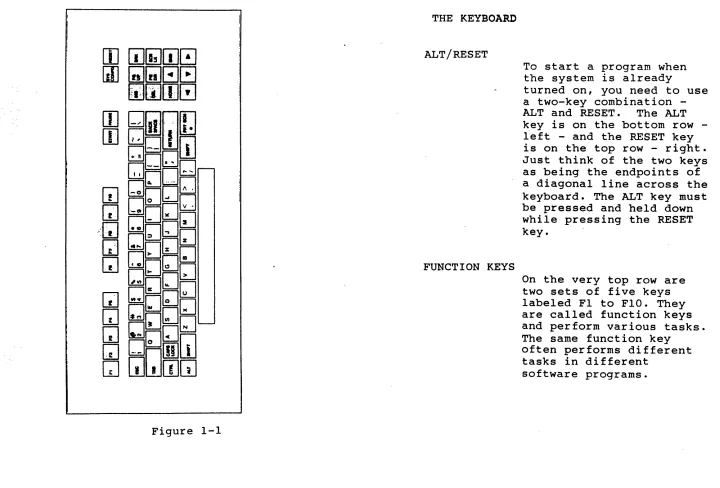
ALT/RESET
FUNCTION KEYS
To start a program when the system is already
turned on, you need to use a twokey combination
-ALT and RESET. The ALT
key is on the bottom row -left - and the RESET key
is on the top row - right.
Just think of the two keys as being the endpoints of a diagonal line across the keyboard. The ALT key must be pressed and held down while pressing the RESET key.
On the very top row are two sets of five keys labeled Fl to FlO. They are called function keys and perform various tasks. The same function key
often performs different tasks in different
software programs.
[image:41.792.41.761.59.547.2]TYPING KEYS
SHIFT
SPACE BAR
RETURN
BACKSPACE
The white set of keys used to type in text. works just like a typewriter keyboard.
is It
To type capital letters, press and hold either SHIFT key on the sides of the bottom row while
typing the letter to be capitalized.
This is the long. key on the very boitom of the keyboard. It is used to create blank spaces between words.
The RETURN key is the wide key on the right of the
keyboard. It is used to
enter commands, to set new values, or to start a new line of text.
The BACKSPACE key above the RETURN key acts as an eraser as you back over the text you have created.
M-3000 Users's Guide 6
VIDEO TITLER II TUTORIAL
.
< (LEFT ARROW)
If you want to backspace without erasing, use the left arrow key on the right hand block of keys.
> (RIGHT ARROW)
The right arrow key moves the cursor to the right without erasing.
A & v (UP and DOWN ARROWS)
ESCAPE
The up and down arrow keys allow you to move up or down one line at a time in most software
applications. In others, it allows you to move an image up and down in small increments.
This key, labeled ESC, is located next to the
numbers on the top left. It is probably the most frequently used key. As you can guess, it helps you to get out of wrong
processes. It gets you
out of menus or it gets you out of doing something
~ ..
HOME
END
DEL
INS
you didn't mean to do, a kind of an "oops" key.
This key puts you back to the start of a page or the start of a sequence,
depending on the software.
If you want to go to the end of a page or a
sequence, use this key.
This key acts as an eraser without moving the cursor. As you are typing text, it erases the character right above the cursor. In the manual mode of the Video Titler II program, DEL blanks out the entire screen, provided the motion was set to "CUT".
With this key you can insert blank spaces or characters into text when you are in the typing mode. In the manual mode
M-3000 Users's Guide 8
PG DN
PG UP
START
PAUSE
of Video Titler II, INS
~alIs ba~~ a ~6~~en t~~t
has just been deleted.
This key gets you to the next page.
This key gets you to the previous page.
This key is used in Video Titler II to start manual mode.
This key stops motion in Video Titler.
2. HOW TO START THE PROGRAM
OBJECTIVE
This section describes how to load the Video Titler II program into the system so that you can use it to create titles and credits or display prepared title sequences.
HOW TO START THE SYSTEM
Turn on the system with the on/off switch located on the front of the
system. A red light on the power switch will turn on.
After a few seconds -- and a few
diagnostic messages.-- you will see the MAIN menu screen giving you seven
choices.
If the M-3000 is'already on, and the MAIN MENU is displayed, you may proceed
from here.
This will start the loading process.
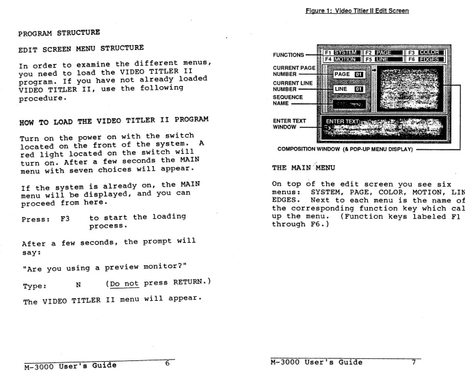
HOW TO LOAD THE VIDEO TITLER II PROGRAM
Press: F3
The Video Titler II program will be
M-3000 User's Guide 10
VIDEO
TITLER II TUTORIALSloaded.
Type: N
After a few seconds, the
prompt will say: "Are you
using a preview monitor?"
(Do not press RETURN.)
The Video Titler II menu will appear and you are ready to go to the next section of this tutorial.
3.
HOW THE MENUS WORKOBJECTIVE
In this section you will learn how to get around the different menus using the
keyboard. We will describe briefly what
the main function of each menu is.
TO GET STARTED
Load the Video Titler II program using the instructions from section 2, IIHOW TO
START THE PROGRAM. II When the ed i t
screen appears, continue.
THE MAIN MENUS
On top of the EDIT SCREEN you see six
menus: SYSTEM, PAGE, COLOR, MOTION,
LINE, EDGES.
Next to each menu is the name of the corresponding function key which calls up the menu.
The menus form three basic groups, each controlling one of the following:
M-3000 User's Guide 12
1.
TITLE SEQUENCESThe SYSTEM menu controls