Performance of Space-Division Multiple-Access Systems Communicating over
Nakagami Fading Channels
Lie-Liang
Yang and Lajos Hanzo
Dept. of ECS. University of Southampton, SO17 IBJ, UK.
. Tel: +4423-8059 3125, Fax: U - 2 3 - 8 0 5 9 4508
Email: Ily,[email protected]; http://www-mobile.ecs.soton.ac.uk
Abslracf- Performance of a space-division multiple-access
(SDMA) system is investigated, when the space-time block coded signals based on two transmit antennas are transmitted over Nakagami-m fading channels. The receiver employs multiple re- ceive antennas, each consisting of several antenna array elements.
In order to gain insight into the multiuser interference resistance of SDMA systems, we consider the employment of a single-user detector. Our simulation results show that in SDMA systems the interfering signals arriving from directions different from that of the desired signal can he efficiently suppressed with the aid of the antenna arrays. However, due to the time-varying characteristics
of wireless channels, aggressive interference may he imposed on
the desired signal, when the interfering signals have a similar di-
rection of arrival (DOA) to that of the desired signal. Therefore, in SDMA systems special emphasis must be put on the suppression of the multiuser interference aggravated by the effects of multipath fading.
I. INTRODUCTION
In wireless communications Multiple-Input-Multiple-Output (MIMO) systems equipped with multiple antennas at both the transmitter and receiver hold the promise of substantial spec- tral efficiency improvements relative to what is achieved at the current state-of-the-art [I], [2], [3]. Recently, MIMO systems have attracted intensive research interests in the context of both their theory and applications, as indicated by [4], [5] and the references in them. It is widely recognized that MIMO systems can he employed for achieving a high capacity 121, [3], a high diversity order [6], [7], for mitigating various types of interfer- ing signals [8], and for supporting multiple users with the aid of space-division multiple-access (SDMA) [8]. The core principle behind the high spectral efficiency achieved by MIMO systems is that when communicating over a rich scattering propagation environment providing nearly independent transmission paths from each transmit antenna to each receive antenna, the mul- tiple antennas employed by the transmitter and/or receiver are capable of providing extra degrees of freedom in the spatial- domain, in addition to the degrees of freedom provided in the conventionally exploited time-domain and frequency-domain.
This
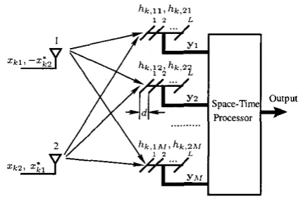
increased degrees of freedom allows wireless systems to increase their capacity, to provide increased diversity, or to sup- press the effects of interference, etc.In this contribution the application of the MIMO principle in the context of SDMA is investigated. Specifically, the uplink communication scenario of Fig. 1 is considered, where each mo- bile user employs two transmit antennas and the hase-station
(BS) employs h I number of receive antenna mays, each of which invokes L number of array elements or sensors. At the transmitter side Alamouti's space-time coding scheme [6] is employed by the mobiles for encoding the transmitted symbols, in order to achieve transmit diversity gain. By contrast, at the BS the signals obtained by sampling the receive antenna arrays' output are linearly combined, in order to detect the informa- tion transmitted by the different SDMA users. In this contribu- tion the employment of single-user detection schemes is stud- ied, where we assume that the receiver has explicit knowledge of the desired user's parameters, including the desired user's direction-of-arrival (DOA) and the corresponding channel im- pulse responses (CIR) with respect to the A I number of receive antenna arrays. However, no knowledge of the other users' pa- rameters is assumed.
The single-user detector considered in this contribution ex- hibits similarities to the conventional correlation or matched- filter (MF) based receivers designed for direct-sequence code- division multiple-access (DS-CDMA) systems [9]. Therefore, it is referred to as the spatial correlation receiver. In contrast
to the popular Rayleigh fading channel model typically used for studying the performance of MIMO systems, in this contri- bution the performance of the SDMA system using the above- mentioned spatial correlation receiver is studied, when com- municating over Nakagam-m fading channels. This generic channel model is used, since the Nakagam-m distribution is a generalized distribution, which often gives the best fit to land- mobile and indoor-mobile multipath propagation environments, as well as to scintillating ionospheric radio links. Furthermore, the Nakagam-m distribution includes the Rayleigh distribution as a special case f o r m = 1. It can also accurately approximate the Rician distributed fading, when m
>
1, with one-to-one mapping between the fading parameter m and the Rician IC- factor. Let us first consider the space-time signals received over the spatial channels considered.Fig. I . Stylised schematic of the space-time block coding assisted tmnsmitter, channel model as well as space-time receiver invoked for the SDMA system using TWO tmsmit mtennz and M receive antenna m a y s .
symbols x1 and x 2 are space-time block coded according to Alamouti's scheme [6] at the kth user's mobile transmitter. The resultant space-time coded symbols are then transmitted dur- ing two consecutive symbol periods. In the first symbol period the symbol transmitted from antenna 1 is Xk1 and the symbol transmitted from antenna 2 is X k 2 . By contrast, in the second symbol period the symbol transmitted from antenna I is - x i 2
and the symbol transmitted from the antenna 2 is zcl, where the superscript * denotes the complex conjugate.
Again, at the base-station there are M number of receiver antenna mays, as shown in Fig. 1. We assume that all the A1
different antenna arrays are located sufficiently far apart so that their received signals experience independent fading. As shown in Fig. 1, each of the Ad antenna arrays consists of L number
of array elements, which are linearly correlated elements sep-
arated by a
distanceof
d.
The
distanced
typically assumesa
value of
5,
namely half a wavelength. We assume thatI<
users are supported by the SDMA system. These users transmit their data synchronously over flat Nakagami fading channels. Fur- thermore, we assume that the complex fading envelope remains constant across two consecutive space-time coded symbol pe- riods. Consequently, based on the above assumptions, the re- ceived signal vectors of the mth BS antenna array during the two consecutive symbol periods can he expressed asK
can be expressed as
where rk.lm and rk,2m represent the mth m y ' s outputs cor- responding to the first and second space-time coded symbol periods, respectively, while dk, represents the L-dimensional complex array vector in terms of the ktb user and the mth an- tenna array. Since we assumed that the array elements are sep- arated by half a wavelength. we have
where
&,,,
represents the direction-of-arrival (DOA) corre- sponding to the kth user and the mth receive antenna array.In ( 2 ) hs,;, = lhk,;mlejek,*-L represents the channel's im- pulse response in the context of the ktb user, the ith, i =
1 , 2 , transmit antenna and the mth, m = 1 , 2 , . . . , A l , re- ceive antenna m a y , where ) h k . i m l represents the fading attenu- ation, while
&,;,
represents the phase rotation imposed by the complex-valued Nakagami fading channel. More specifically, we assume that the fading attenuations { Ihk,imI} are indepen- dent Nakagami random variables having a probability density function (PDF) ofwhere
r(
,) is the gamma function, m is the Nakagami-m fading parameter, while R in (4) is the second moment of.lhk,,,l, i.e., we have R = EIJhr.tmlZ].Let
Then, rk, in (2) can be written as
T
Furthermore, let Y = [yy yz
. .
. yTf].
Then it can be read- ily shown that the received signal of ( I ) can be written as ym =1
rk,+
nmr m = I , 2 , . . . , M , (1)k=l K
Y = D k H k X k
+
n,(7)
where ym is a 2L-dimensional vector representing the outputs of the mth antenna m a y associated with a space-time coded pe- riod bv two consecutive svmbol oerids. and n, is
k=l
where Dr represents the ktb user's array-related matrix, which a 2L-dimensional vector representing the additive white Gaus-
sian noise (AWGN). Each element of n, is modelled as an independent identically distributed (iid) complex Gaussian ran-
can be expressed as
D k l 0
...
00 D k 2 . _ _ 0 dom variable with zero mean and a power spectral density of
No12 per dimension. Furthermore, in (1) rk, represents the
received signal component contributed by the kth user, which
D~ =
.
.
0 0
. . .
D k n r, k = 1 , 2
,...,
K (8) [image:2.614.107.319.68.209.2]while Hk is the channel-related matrix of user k , which can he expressed as
Ht =
[HZ
HC2. . .
Hrn',,]T,k
= 1 , 2 , . . .,
K. (9)Finally, in (7) n = [nT nS . . . n t ] IS a 2ML-dimensional AWGN vector, which is a zero-mean Gaussian vector having a covariance of
T .
R, = E [nn"] = NoIznr~, (10)
where the superscript represents the conjugate transpose op- eration, while Iznrr. is the identity matrix of size 2AtL.
Having characterized the SDMA signal, below the single- user spatial correlation detector is investigated, where we as- sume that the receiver only employs the knowledge of the de- sired user's parameters. More explicitly, this knowledge in- cludes both that of the array vector in (3) and that of the channel states in (5) in the cnntext of the desired user. Specifically, let us assume that the first user is the user-of-interest, and assume that the receiver employs the knowledge of dll, d12,.
. .
,
dlnr as well as the knowledge of Hn. H ~ z , . . .,
Hlnr. The objec- tive of the receiver is to detect x1 = [ q i , 2121 transmitted by the user-of-interest associated with the user-index of k = 1.111. SPATIAL CORRELATION DETECTION OF SDMA T
SIGNALS
In this section we consider the spatial correlation detection of SDMA signals. Firstly, the specific case of supporting I<- = 2 users is considered. Then, the results obtained for K = 2 users are extended to the general case of supporting K
>
2 number of users.Alamouti's space-time code 161 has the property of
HfmHlm = (Ihi,im
Iz+
lh1.2, /')Iz. Consequently, in the spe- cific case of K = 2 users, the decision variables corresponding to the two symbols transmitted by the first user can he obtained by multiplying both sides of (7) with ( D I H ~ ) ~ , which can heexpressed as
'11 = ( D ~ H ~ ) H D H X
+
n,
(11)z l =
[
'12I
where(12)
It can he shown that for a given set of fading values associated with user I , 6 is a zero-mean Gaussian vector having a covari- ance matrix expressed as
H n = ( D I H 1 ) n.
Upon substituting DI of (81, and Hi of (9) into (1 I), it can be shown that the expression of Z1 can be simplified to
A1
ZI = L (lhi,im12
+
Ih1,zml2) (xi+
Rizxz)+
6 , (14)m = l
where R12 represents the correlation matrix evaluated for user
1 and user 2 in terms of the array responses as well as channel states, which can he expressed as
R12 =
(.
g ( l h 1 , l m l Z+
Ih1,zml ? ) - I m = 1AI
x
1
H F ~ D F ~ D ~ , H ~ , .
(15) "L=1Since the channel amplitudes are random variables, we infer from (15) that user 2 will impose interference on user I , if there is a non-zero correlation between the array vector D1, of user 1 and the array vector Dzm of user 2 for
m
= 1 , 2 , .. .
, A t ,i.e. if we have DfmD2,
#
0 for any value ofm,
where 0represents a matrix having elements of zero. By contrast, when these two users' signals are spatially orthogonal, i.e. when we have Dfm!,D2;, = 0 for any value of m , then we have Rlz = 0. Consequently, in this scenario user 2 imposes no interference on user 1. Furthermore, upon substituting DI,, Dzm. HI, and
Hzm from (5) into (15), Rlz can he written as
),-I
M
~ 1= 2
L1
C
(Ih1.1mI2
+
1h1,2,1').
x 2 [
h;.imh2,1mP1z.m+
h 1 . 2 m h L & ~h ; , z m h ~ , l m ~ 1 2 , m - h ~ , ~ m h k n ~ ? z , m m = l
h;,imh2,2n~12,m - h ~ , ~ m h ; , l m ~ L . m
1,
(16)where plz.,, represents the spatial correlation factor between the array vectors of user 1 and user 2 associated with the mth
antenna array. Explicitly, ~ 1 2is given by . ~
K , Z ~ ~ Z . Z ~ P I Z , ~
+
h1,1mh;,lm~72.m(17) 1
~ 1 2 , ~ = -dFmdzm. L
Having considered the detection of K = 2 users, the results can he readily extended to an arbitrary value K . By remem- bering that the received signal was expressed in (7), it can he readily shown that when
K
number of users are supported, the decision variable Z I corresponding to the symbols transmitted by the first user can be formulated aswhere n is given by (12), while Rlk represents the correla- tion matrix evaluated for the desired user and the kth interfer- ing user. The correlation matrix Rlk has the same form as (16),
except that the user-related subscript of 2 is now replaced by k .
IV. PERFORMANCE RESULTS
In this section we provide a range of simulation results, in order to illustrate the achievable performance of the SDMA system considered in conjunction with the spatial correlation receiver. As an example, we assumed that in the SDMA sys- tem each mobile user was equipped with two transmit anten- nas, while the BS employed AT = 2 receive antenna arrays, each having L = 2 array elements. Furthermore, in order to provide an insight into the effects of the multiuser interference as a function of the users' specific spatial signature, we assumed that only K = 2 users were supported by the SDMA system, where one of them was the desired user and the other one was the interfering user.
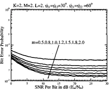
Fig. 2 shows the bit error rate (BER) versus signal-to-noise
(SNR)
per hit, i.e. E 6 / N o performance of the SDMA sys- tem, with respect to the Nakagami fading parameters of m = 0.5, 0.8, 1.0, 1.2, 1.5, 1.8 and 2.0. In this scenario we as- sumed that the SDMA system supported K = 1 user. Hence, no multiuser interference was imposed on the desired user. As shown in Fig. 2, the BER performance improves, as the fading becomes less severe, i.e. as the Nakagami fading pa- rameter's value increases. According to the results of Fig. 2 we also observe that in the presence of a single interfer, the MlMO based SDMA system is capable of achieving a low BER even in the low SNR per bit range. As shown in Fig. 2, for the worst transmission environment considered, which corre- sponds to m = 0.5, a BER of can he achieved at an SNR of &,/NO = 8dB. By contrast, for the best case consid- ered, namely for m = 2.0, a BER of lo-' may be achieved at an SNR of ETJ~VO = 6.5dB. Note that these low BERs are achieved, since the SDMA system is capable of efficiently ex- ploiting the joint benefits of combined transmit diversity, re- ceive diversity as well as receiver beamforming.In Fig. 3 we show the BER versus SNR per bit performance of the SDMA system considered, when it supports K = 2 users. In our simulations we assumed that the DOA angles were $11 = $]2 = 30' for user 1 and = dJZ2 = 60° for user 2. According to the results of Figs. 3 we observe that as in Fig. 2, the BER performance improves, when increasing the Nakagami fading parameter's value. However, as a conse- quence of the identical DOA angles of the desired user and the interfering user, aggressive multiuser interference is imposed on the desired signal. Consequently, in contrast to the results of Fig. 2 , Fig. 3 demonstrates that the BER performance was sig- nificantly degraded and hence relatively high error floors were observed in both of these figures.
In order to demonstrate the effects of various DOAs on the achievable BER performance, Fig. 4 and Fig. 5 show the BER versus the DOA performance of the SDMA system considered. As in Fig. 3, in Fig. 4 we also assumed that the DOAs recorded, when transmitting from a mobile user to different BS receive antenna arrays are perfectly correlated. More quantitatively, for the desired user we assumed that we had GII = = O',
while for the interfering user we had = $22. which as- sumed angles spanning the range [-180°, 180'1. In the context
of Fig. 5 we assumed that the DOA recorded when transmitting from each of the mobile transmit antennas to each of the BS re- ceive antenna arrays were independent. The results of Fig. 5 were obtained by assuming that we had QI1 = $12 = Oo,
and that both and +22 assumed values in the range of [-180", 180'1. From the results of Figs. 4 and 5 we observe that when the interfering signals are spatially orthogonal to the desired signal, the multiuser interference can be efficiently mit- igated by the BS's receiver with the aid of the associated beam- forming applied to the BS's receiver m a y output signals. Fur- thermore, the results of Fig. 5 suggest that the BER perfor- mance can he significantly improved, provided that the inter- fering signal is orthogonal to the desired signal at either of the BS's receive antenna arrays. However, when the interfering sig- nals impinging upon both of the BS's receive antenna arrays have similar DOAs to that of the desired users' signals, then the interfering user will impose strong interference on the desired users.
V. CONCLUSIONS
In this contribution a SDMA system has been proposed, where each mobile transmitter has two transmit antennas and the BS receiver is constituted by AT number of antenna ar- rays, each having L elements. The performance of the pro- posed SDMA system has been investigated, when the SDMA signals considered are detected using the so-called spatial cor- relation detection scheme. The achievable BER performance of the SDMA system has been evaluated, when assuming that the SDMA signals are transmitted over Nakagami-m fading channels. Our simulation results demonstrate that the proposed SDMA system is capable of suppressing the interfering mul- tiuser signals having DOA angles sufficiently different from that of the desired signals. By contrast, strong multiuser in- terference may be imposed on the desired signals, when these interfering signals arrive from similar directions.
REFERENCES
[I] J. H. Winters, "On the capacity of ndio communication systems with diversity in a Rayleigh fading environment." lEEE Joumol on Selected
Areos in Cornmunicnrions, vol. SAC-5, pp. 871478. June 1987.
[2l 1. E. Telatar. "Capacity of multi-antenna Gaussian channels," Eumpeon
Transactions on Telecommunicorions. vol. IO, pp. 585-595. Nov./Dec.
1999.
[3] A. Goldsmith. S . A. lafar. N. Jindal, and S . Vishwanath. '.Capacity limits of MlMO channels,"lEEEJoumol on Selecfed Amas iu Cormununicafiow,
vol. 21, pp. 68G702. June 2003.
[4] "Special issue on MUlO systems and applications," lEEE Joumol on Se- IecredArear in Communications. vol. 21, April 2003.
[SI "Special iswe on M M O systems and applications," lEEE Joumol on Se- IecredAreos in Communications, vol. 21. May 2003.
[61 S. M. Alamouti, ' A simple " i t diversity technique for wireless communications:' IEEE Joumol on Selected Areos in Communications, vol. 16, pp. 1451-1458. October 1998.
[7] V. Taroh. N. Seshadri, and A. R. Calderhd, "Space-time cades for high data n t e wireless communication: performance criterion and code con-
struction," lEEE Tmnrncrions on h,fonnofion Theoq, vol. 4 4 , pp. 7 6 765. March 1998.
[SI A. F. Naguib and R. Calderbank, "Space-time codin% and signal process- ing for high data rate wireless communications:' Wireless Communica- rims andMObile Computi&, vol. I, pp. 13-34, Januaq-March 2001.
m=0.5
m=1.0
[image:5.614.324.512.107.257.2] [image:5.614.87.272.114.261.2], a ~ K=2, M=2. L=2. E,/N&dB
...
-
60 120 180-120 -60 0
lo",,
DOA difference between user 2 and user I
Fig. 4. BER performance of the SDMA system as a function of the duection- of.arrival (DOA) angular difference of the interfering signals. In our simula-
= transmit antennas, = receive antenna Of each having tions we assumed that for a given user. the DOAs recorded the first and second
i.e. we assumed ill = q,,2 = 00
and Q~~ = d,22, ~h~ DOA difference is defined as d2,
-
$,,.me
pamameters used were T, = 2, M = 2 , L = 2 and the Nakagami-m fading
Fig. 2. UER VCKUS SNR per bit performance of the SDMA system using L = 2 senson, and supporting K = 1 number of user. when communicating
over the Nakagami-m fading channels corresponding to the fading p x m e t e r s o f m = 0 . 5 , 0 . 8 , 1 , 1 . ? , 1 . 5 , 1 . 8 , 2 . 0 .
were perfectly
panmeters were m = 0.5, 1, 1.5.
K = 2 , M = 2, L = 2,m = 1.5, Eb/No = 5 d B
Fig. 3. UER versus SNR per bit performance of the SDMA system using
Tr = 2 transmit antennas, M = 2 receive antenna "ays, each having L = 2 sensors, und supporting IC = 2 number of user, when comunicvting over vuous N & ~ - . ~ fading channels corresponding
of m = 0.5,0.8,1,1.2,1.5,1.8,2.0. Funhemore, in our simulations we as.
sumed that, for a given user the DOAs recorded at the first and receive we assumed ill = iI2 = 300 and
$21 = $22 = 60".
Fig. 5. BER versus DOA perfomlance of the SDMA system using T z = 2 mobile transmit mtennas, M = 2 US receive antenna " a y s each having L =
2 Sensors. and supponing A' = 2 Users, when comunicating over Rayleigh fading channels corresponding 10 the N k a g h P-eter Of m = 1. In this
figure DOA 1 and DOA 2 represent the DOA differences between the signals of user 2 and user 1 as received. by the first and second BS antenna m a y s respectively.
the fading
were perfectly correlated,
[image:5.614.302.540.396.544.2] [image:5.614.89.274.399.548.2]