CRYSTALLIZATION
Additives: Molecular Design
J. H. ter Horst and R. M. van Rosmalen, Delft University of Technology, The Netherlands R. M. Geertman, Akzo Nobel Chemicals Research, Arnhem, The Netherlands
Copyright^ 2000 Academic Press
Introduction
Crystallization is the nucleation and growth of a solid phase in a mother liquor. It can be used as a separ-ation technique, because the process results in the separation of the mother liquor and the solid phase. If the mother liquor and the solid phase have differ-ent compositions it can also be used as a puriRcation technique. In such cases the mother liquor must con-tain impurities. The deliberate addition of impurities during the crystallization process, has been widely used to improve both the product quality and the process performance. However, most impurities pres-ent during crystallization processes are not added on purpose, but are by-products from previous reac-tions, dissolved salts and solvents that can have the same kinds of effects.
In industrial crystallization additives are generally used to improve the handling characteristics of the crystalline product or to prevent scaling. By employ-ing correctly selected additives it is possible to reduce caking, improve the free Sowing behaviour of a powder, increase the bulk density of a crystalline product, change the crystal size distribution, induce certain polymorphs and improve Rltration behaviour.
Varied though this list may seem, all these ef-fects can be achieved by using additives that have very speciRc interactions with the crystal surface. This fundamental physical effect causes a change in the system parameters when additives are introduced. Detailed knowledge of the molecular structure of the solid}liquid interface is very important for design of additives. Once this interface is understood, it is possible to design molecules that have speciRc interactions with one or more of the faces of a crystal. Often the same additive can be used in different application. For instance a growth retarder used to prevent scaling of a given compound can, when ad-ded after crystallization, also act as an anticaking
agent. Blocking a single crystal face with a certain additive can induce morphology changes, but the same additive can also be used to act as a template for the nucleation of that same crystal face.
In many cases additives are not wanted in the product application. Ferrocyanide is a very effec-tive anticaking agent for salt (NaCl), but the ferro-cyanide complex must be destroyed and the iron precipitated prior to electrolysis of the salt for the production of chlorine (Cl2). Nitrosyltriacetamide is also an effective anticaking agent for salt, but during electrolysis nitrogen trichloride (an explosive) is formed.
Apart from having a very speciRc inSuence on a crystal face, additives must also be effective at very low concentrations. Because one of the main uses of additives is in cheap bulk products (costing less than US$1 kg\1) the price of the additive also acts as an incentive to keep the additive concentra-tions as low as possible. Expensive additives, even if used in very low amounts, will adversely affect the cost of these cheap bulk products. High additive concentrations always give rise to signiRcant additive incorporation in the crystal and thus decrease the product purity.
Additives that effectively control crystallization processes are also found in nature: the shells of crus-taceans are formed as a result of bio-templated growth of calcium carbonate; the growth of the min-eral components of our bones and teeth is carefully regulated; and studies of Rsh in polar regions have revealed some proteins that very effectively block the growth of ice crystals.
After describing the fundamental effects of the additive in the crystallization system, a general procedure for the molecular design of additives will be given. The review ends with some case studies.
Interaction of Impurities and
Crystal Surfaces
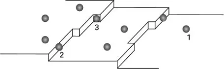
Figure 1 Additive adsorption at various positions on a crystal surface: 1, flat surface; 2, step; 3, kink site.
Adsorption of the impurity can take place onSat surfaces, at stepped surfaces and at kink sites ( Fig-ure 1). The adsorbed compound can impede the movement of steps on the surface. This is a kinetic effect and causes a reduction in the growth rate of the corresponding crystal surface. For instance the induction time, i.e. the time that elapses until the outgrown nuclei are detectable, can increase because the outgrowth of nuclei takes longer.
Origin and Type of Impurities
In solution crystallization the solvent is an inevitable impurity. Additives play a role in the improvement of product quality (e.g. shape of the crystals, crystal size distibution) or process performance (e.g. Rlterability). One source of impurities in the crystalli-zation process is the synthesis of the crystal com-pound, as synthesis by-products greatly affect crystallization.
Impurities can also be classiRed based on their character. Apart from organic and inorganic com-pounds, a special group of impurities is the polyelec-trolytes, long carbon chain molecules with many functional groups. Because of the large number of functional groups the interaction between polyelec-trolytes and crystal surfaces is strong. The large num-ber of functional groups also makes the molecule kinetically very hard to remove, as all the bonded functional groups have to be detached from the sur-face. One of the detached functional groups remain-ing bonded to the polyelectrolyte and is thus posi-tioned very near the crystal surface. The attachment of that one functional group onto the surface is faster than the detachment from the surface of the other functional groups of the polyelectrolyte molecule. The strong interaction and the large number of inter-action points make polyelectrolytes highly effec-tive addieffec-tives at very low concentrations. Another special group of impurities is the crystallizing com-pounds themselves. Long chain hydrocarbons such as fats may cause self-poisoning on certain surfaces if the fat molecules in the melt near the surface have a different conformation from the fat molecules in the surface.
Predicting the Effects of
Impurities
The deliberate addition of an impurity is intended to cause a particular effect, such as a reduction in mineral scale formation or a change in morphology. This effect comes from changes in the kinetic process involved, e.g. for a change in morphology the relative growth rates of the different crystal faces have to change. The function of the additive is thus very speciRc: the morphology changes if the growth of a speciRc face is blocked. This is illustrated in Table 1 for a number of desired additive effects. The Rrst column gives the desired effect, the second the kinetic process involved and the third the action acquired by the additive. Table 2 shows whether an interaction with a speciRc face or all faces is required, at what particular moment the additive should be added and whether it blocks a face or acts as a template. This table shows the close relationship between additives used for different purposes. An anticaking agent is simply an antiscaling agent added after crystallization, and an additive used to block a speciRc crystal face can in some cases also act as a template for that same face.
IdentiRcation of an unintentional impurity and un-derstanding of its effect on the crystallization process requires a kind of reverse engineering. Many impurities are formed as by-products during the syn-thesis of the compound to be crystallized. By observ-ing how the crystallization process changes in the presence of impurities, the kinetic process involved can be identiRed. The effect on the process then can be matched with the expected (predicted) ef-fect of one of the impurities present. This is a rather complicated procedure because not all the impurities present that can act on the kinetic processes involved will be known.
Table 1 Additive effects on the crystal growth process
Desired effect Kinetic process involved Action required
Anticaking Dissolution and regrowth of crystalline material
Complete blocking of growth
Antiscaling Complete blocking of nucleation and/or growth
Complete blocking of growth
Changing morphology (filtration, flowability) Ratio of growth rates of different faces Block specific faces
[image:3.568.52.520.583.712.2]Control of polymorphism Nucleation of a given polymorph Mimicing a face of the desired polymorph Changing crystal size distribution Changing nucleation/growth ratio Block specific faces, or block all faces
Table 2 Details of additive effects on product properties
Effect on product property
Interaction with Addition Effect on face
Specific face
All faces Before During After Blocking growth
Template induced growth crystallization crystallization crystallization
Anticaking ; ; ;
Antiscaling ; ; ; ;
Morphology ; (;) ; ;
Polymorphism ; ; ;
Crystal size distribution
(;) ; ; ;
nuclei can be deduced. From these effects the inSuence on the crystal quality and the product hand-ling characteristics and ultimately the product prop-erties can be determined. The starting point for de-signing and studying additives is therefore a study of the molecular structure of the crystalline interface.
Molecular Structure of the Crystal
Surface
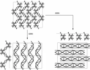
Both the impurity and the crystal surface determine the strength of the interaction. A crystal has several crystal surfaces, which might have totally different mo-lecular structures. Crystal faces are identiRed by Miller indices, which indicate how the faces are cut from the crystal unit cell. Figure 3 shows a unit cell and two crystal surface structures for the compound RDX (cyclotrimethylene trinitramine) with different Miller indices. Since the molecular structures are very different, the interactions of the impurity with the surfaces might also be very different. The growth of one face might be blocked because of strong interac-tions, while the other face can grow freely because the interactions are only minor. This can cause face-speci-Rc growth retardation.
Prediction of the Molecular Structure
of the Crystalline Interface
A morphology can be geometrically constructed by drawing planes with an orientation (hkl) having a
dis-tance from the origin proportional to the growth rate. The central volume enclosed by the set of planes is the growth form. A face with a large growth rate is positioned far from the origin, and thus its surface area will be small. In contrast, a face with a small growth rate will be close to the origin and have a large surface area (Figure 4). This means that the morpho-logy is determined by the slowest growing (hkl) faces and that a morphology prediction can be made if the relative growth rates of all the different (hkl) faces are known.
Figure 4 also shows the effect of a growth-retarding impurity. Before a crystal face can grow the adsorbed impurity has to be removed from the sur-face. This takes energy, and thus the growth rate decreases. When face-speciRc adsorption occurs, sur-face concentrations of the impurity vary from sur-face to face. The growth retarding effect will then also vary from face-to-face. When face-speciRc adsorption occurs, the relative growth rates may change, as shown in Figure 4.
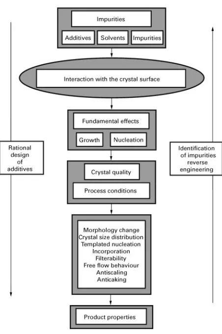
Figure 2 The interaction between the surface and the impurity is the key to the effect of the additive in the crystallization process. This effect translates to changes in the growth and nucleation behaviour of the crystal compound, which in turn affect the crystal quality and process parameters and thus the product properties change.
crystal unit cell is the attachment energy method. The attachment energy is deRned as the energy release per growth unit upon adding a growth slice of thickness dhkl onto the corresponding crystal surface. The assumption that the attachment energy is linearly proportional to the relative growth rate of the corresponding crystal surface gives the morphology prediction.
The Design Method
These vacuum morphology prediction methods do not take into account the actual growth processes taking place on a molecular scale at the crystal surfa-ces. Our goal is to predict the effect of an impurity that affects these growth processes. Such a method should include calculations of the interaction energy between the impurity and the surface. This interac-tion energy affects the molecular growth pro-cesses taking place at the surface.
To make such a prediction, knowledge mustRrst be obtained about the crystal surface structures present. Simple energy calculations determine the mor-phologically important surface structures. Then more sophisticated calculation methods such as molecular mechanics, molecular dynamics, Monte Carlo tech-niques or even quantum mechanical calculation methods are needed to calculate the interaction ener-gies of the morphologically important crystal surface structures with the impurity. These interaction ener-gies can be translated into growth rates of the surface structures by assuming a model which interrelates growth rate and interaction energy. The general method for the design of additives is shown in Fig-ure 5.
A good way of determining surface structures and their morphological importance is by performing a periodic bond chain (PBC) analysis. A PBC is an uninterrupted chain of strong bonds between growth units in which periodicity is based on the unit cell parameters and symmetry and which is stoichiomet-ric with regard to the unit cell content. Two sets of intersecting PBCs make a connected net. The connec-ted net can be considered a (hkl) growth slice or growth layer. If a surface does not contain a con-nected net, the surface cannot grow with a layer growth mechanism and is rough. This means that the relative growth rates of (hkl) surfaces that do not contain connected nets, are very large. These surfaces are not present on the crystal morphology, as a surface needs to contain a connected net to be present. If a surface contains more than one connec-ted net (slices at different heights) more surface structures are possible for one crystal surface. Energy calculations should determine which of the surface structures actually occurs on the surface. However, it is important to remember that the morphologically important surface structure for a particular (hkl) surface may change because of interactions with impurities.
The morphologically important surface structures can be determined by calculating the attachment en-ergyEaof a surface slice containing a connected net from the bond energies in the slice (the slice energy Esl) and the lattice energyEcr. The attachment ener-gies of all the possible surface structures can be used to determine the relative growth rates of these surface structures:
RJEa"Ecr!Esl
Figure 3 The RDX (cyclotrimethylene trinitramine) unit cell (top left), and the (2 0 0) and (0 2 0) slices, indicating their surface structure. For the (2 0 0) slice the connected net is given on the right of the molecular view of the slice while for the (0 2 0) slice the connected net is given below the molecular view of the slice, as they occur in the unit cell. The surfaces are given perpendicular to the paper. The dotted line in the molecular view of the surfaces indicates the surface.
Figure 4 The faces with the smallest growth rates determine the morphology. A growth rate decrease (R3PR3) because of
a face-specific interaction of the foreign compound causes a mor-phologically more important surface and thus a change in the morphology.
Commercial software packages nowadays have several tools to calculate interaction energies of one or more impurity molecules on these surface struc-tures.
Once the interaction energies have been calculated, they should be related to the growth rates of the crystal surface structures. The models used for this relation are generally based on the assumption that interaction reduces the growth rate. First the impurity has to be removed from the surface before the face can grow. This takes energy and thus the growth rate decreases. An energy correction termEsfor the vac-uum attachment energy can be introduced, which is a function of the interaction of the impurity and the Sat crystal surface structure:
RJEa"Ea!Es
In most cases only the interaction of a single ion, complex or molecule with the different crystal surfaces has to be considered. By determining the strongest interactions the corrected attachment ener-gies can be calculated and changes in the morphology can be predicted.
[image:5.568.52.277.502.653.2]Figure 5 Method of calculating the effect of an impurity on the growth rates of the different crystal faces.
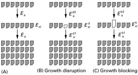
Figure 6 Tailor-made additives can act as growth disrupters or growth blockers.
crystalline interface can be estimated, and thus the interaction energyEscan be calculated. The proced-ure has to be repeated for all important faces. Though this procedure is somewhat tedious, it yields impor-tant insights as to how a solvent can inSuence the morphology.
Tailor-Made Additives
Tailor-made additives are usually organic additives that are especially designed to aid in the crystalliza-tion of a particular organic crystal compound. The additive can be designed to work only on a very speciRc crystal surface. Again, the additive works by blocking the growth of this crystal surface, making the surface morphologically more important. A char-acteristic tailor-made additive is very similar to a building unit. The interaction energies needed for adsorption of the building unit and the additive to the surface are similar. Therefore if the additive is adsor-bed, it will be relatively hard to remove it from the surface. To retard the growth of the crystal surface, the additive molecule needs a functional group that differs from the growth unit. The functional group may be chosen so that the additive molecule still resembles the building unit, but is smaller. The tailor-made additive is then of the disruptive type. If, because of its functional group, the additive molecule is much larger than the building unit, the additive is of the blocking type (Figure 6).
The attachment energy of a growth unit that be-longs to a certain crystal surface can be assumed to be linearly proportional to the growth rate of that crys-tal face. If the slice to be attached contains an addi-tive, the slice energy changes. However, this change will be small if the additive strongly resembles the building unit (as is the case in both Figure 6B and Figure 6C: Esl+Edsl+Ebsl). Slices with tailor-made additives will also have a similar attachment energy:
Ea+Ed1a+Eb1a. The difference between crystalli-zation with and without a tailor-made additive is the attachment energy of a subsequent normal slice onto the slice with the additive in it. This attachment energy (Ed2
a, Eb2a) is decreased because of the func-tional group of the additive.
A disruptive type of additive will cause a decrease in the attachment energyEd2
a compared with the nor-mal attachment energy Ea because some bonds be-tween the attaching slice and the surface cannot be made. Because the attachment energy decreases, the growth rate of the crystal surface decreases. During crystallization the disruptive additive can be incor-porated in the lattice.
A blocking type of additive will cause a very large decrease in the attachment energyEb2
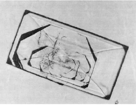
[image:6.568.288.519.557.682.2]Figure 7 An RDX (cyclotrimethylene trinitramine) crystal grown from the solvent cyclohexanone. A blocking type impurity in the system causes very large macrosteps on a particular surface and inclusions in the interior of the crystal.
a blocking additive can also have a functional group that is differently charged from the growth unit, and therefore rejects an incoming growth layer.
This approach can also be used for reverse engin-eering to Rnd an impurity in the system that causes problems such as incorporation in the lattice or inclu-sion formation, especially when synthesis by-prod-ucts that strongly resemble the building units are known to be present as impurities. Disruptive impu-rities, which have a tendency to incorporate into the lattice, can be distinguished from blocking impurities, which can cause macrosteps and thus inclusion formation. Inclusion formation is the incorporation of pockets of mother liquor into the crystal. A crystal grown from a solution containing a blocking impu-rity is shown in Figure 7. Very large macrosteps are visible on the crystal, and small inclusions also appear in the interior of the crystal.
Incorporation of Impurities
Impurities obviously reduce the purity of the crystal-line product and are seldom beneRcial to the crystalli-zation processes or the product characteristics. As with the design of additives, it is important to under-stand how the impurities are incorporated in the crystalline product to reduce their uptake.
In general an impurity is included in the crystalline product through either direct incorporation in the lattice (solid solubility), the formation of inclusions, surface adsorption or poor washing of agglomerates. These incorporation mechanisms will be discussed in more detail.
Solid solutions can only be formed when the impu-rities mimic the main compound in form and charge.
They are especially likely to occur with organic crys-tals where closely related by-products are formed during synthesis of the product. Examples are 2,6-dimethylnaphthalene in naphthalene, cyclohexanone in caprolactam and bromide in sodium chloride. This phenomenon can only occur when the crystallization enthalpy of the impurity is very close to that of the main compound. If that is the case, not only will the impurity be easy to include in the crystal lattice, but the growth will not be retarded. In other words, compounds that form high concentration solid solu-tions have a very limited inSuence on the growth of the main compound. If the impurity resembles the main compound to a lesser extent the solid solubility will decrease and growth will be hindered. The free enthalpy involved in the incorporation of polymers or polyelectrolytes, which are the most effective ad-ditives in mineral scale prevention, is so large that they are not incorporated in the lattice by direct substitution for molecules or ions of the main com-ponent.
A second incorporation mechanism is inclusion formation. Inclusions can be formed in several ways. The most common mechanism in industrial crystalli-zation involves imperfect regrowth of corners damaged by attrition. Pockets of mother liquor are then trapped. The concentration of impurity in the inclusion is then directly related to the concentration in the mother liquor. The overgrowth of poisoned areas is another type of inclusion formation, and occurs at higher driving forces for crystallization. This is essentially the only way to overcome the blocking effects of polymers and polyelec-trolytes. As discussed previously, the concentration of polymers or polyelectrolytes in solution is low be-cause these additives are effective at low concen-trations and most of the additive is adsorbed on the crystal surface. The amount of additive in the product will therefore not increase much, but of course the amount of other impurities present in the mother liquor, such as solvent, will increase.
A third incorporation mechanism is adherence to the surface. ‘Normal’ impurities, which cannot be incorporated in the lattice, can be washed off fairly easily. Tailor-made additives, however, are designed to adhere to the surface and are difRcult to remove. Partial dissolution of the crystals is not an effective solution as these additives may also hamper the dissolution process. Washing is therefore very useful for the removal of ‘normal’ impurities, but less so for tailor-made additives.
Figure 8 The-lactose hydrate crystal grown in the presence of-lactose. The (0 1 0) surface on the right is blocked because
-lactose can adsorb on the surface, causing a blocking impurity as shown in Figure 6C, while on the left the (0 1 0) surface is not blocked because the-lactose can not adsorb on the surface. product through a combination of careful
crystalliza-tion and after treatments (washing, etc.). Compounds such as tailor-made additives are much harder to remove.
Case Studies
To illustrate the general principles four cases will be discussed. These cases show the variety of possible applications of additives and the problems sometimes associated with the presence of impurities in the mother liquor. Scaling inhibition is demonstrated us-ing barium sulfate as an example, diesel fuel additives illustrate how the crystal size distribution can be changed, crystallization of -lactose is a good example of self-poisoning, and the template directed crystallization of calcium carbonate is also discussed. Scaling problems are often encountered in oil pro-duction. The two major scaling problems involve gas hydrates and mineral scaling. Gas hydrates occur when methane and water crystallize under high pres-sure to form clathrate structures; this can happen in gas pipes on the bottom of the sea. These crystals can scale and block the pipes. Nowadays much research effort is put into the design of additives to pre-vent these clathrate crystals from blocking the pipes. Mineral scaling occurs in secondary oil recovery. When the immediate vicinity of a borehole becomes depleted in oil, water is injected in the surrounding rock strata to push the remaining oil from the pores towards the borehole. The pores also contain water that at these deep levels contains a high concentration of barium. When seawater (which contains large amounts of sulfate) is injected, barium sulfate precipi-tates and the pores silt up. In the worst case the pores are plugged and a new hole must be drilled, which is a very costly operation. Scale formation is inhibited by the addition of low amounts (ppm levels) of electrolytes, for instance polycarboxylates and poly-sulfonates. Experiments have shown that the molecu-lar structure of the polyelectrolyte determines the effectiveness of the additive. Polyelectrolytes containing sulfonate or phosphonate groups, which closely resemble the sulfate groups in the crystal lat-tice, are more effective than polyelectrolytes con-taining only carboxylate groups. Also the way the sulfonate groups are attached to the backbone is important: molecules with the sulfonate group directly attached are more effective than molecu-les with the sulfonate indirectly attached. The length of the backbone allows each sulfonate group to re-place a sulfate in the lattice, thus binding the additive very strongly to the crystal surface, in a zipper-like manner, and inhibiting growth. For instance, 0.1 ppm of a polymaleic acid (polyvinyl sulfonic acid
at a pH of 3.8) decreases the growth rate of barium sulfate by nearly two orders of magnitude (depending on the supersaturation).
Waxes in diesel oil can crystallize at low temper-atures. The crystals clog up the fuelRlters in cars and prevent the motor from starting. To prevent this problem either wax crystallization should be pre-vented or only very small crystals should be allowed to form, which can pass through the fuelRlter with-out any problem. As the former option is not very practical (it requires either removal of the waxes or storage of the fuel at higher temperatures) the only option is to add additives that block crystal growth. The design of an additive for such a purpose has been carried out using xylene containing n-C32H66 as a model fuel. A copolymer of fumarate vinyl acetate with different alkyl side chain lengths was used as an additive. The effective concentration at which the additive started to inSuence the growth of n-C32H66was determined at aRxed supersaturation as a function of the alkyl side chain length. A clear relationship between the side chain length and the growth inhibition was shown, with a maximum ef-fectiveness when the chain length was very close to the chain length of the solute. This shows that the structural match between the additive and the solute is critical for the effectiveness of the additive.
A substance that is capable of crystallizing into structurally different but chemically identical crystalline forms exhibits polymorphism. A very com-mon compound that can form polymorphs is water. Under atmospheric pressure and slightly below 03C ice is formed with a density lower than that of water, so the iceSoats on the water. Under higher pressure the ice can crystallize into polymorphs with higher densities that sink. Different polymorphs crystal-lize under different conditions. However, these conditions may be almost equal for rather complex organic compounds such as pharmaceuticals. In the pharmaceutical industry a strong desire exists to con-trol the crystallization of polymorphs for a number of reasons. The polymorphic form of a pharmaceutical inSuences its effect and its lethal dosage. The crystallization processes of particular polymorphs are therefore protected by patents.
One way of controlling the crystallization of the correct polymorph is by means of template-directed nucleation of the polymorph. The template mimics a crystal face of the desired polymorph and nuclei of that polymorph can form onto the template. Up to now attention has mainly focused on templates con-sisting of Langmuir}Blodgett (LB) layers.
Calcite and vaterite are polymorphs of the com-pound calcium carbonate (calcite is the polymorph that forms under ambient conditions). Stearic acid spreads at the air}water interface, which when com-pressed as a LB monolayer is highly structured. When the acid group is ionized at higher pH the monolayer surface facing the solution consists of carboxylates that can bind calcium ions from the solution. At higher calcium concentrations calcite grows from the (1 1 0) face under the monolayer, while at lower calcium concentrations vaterite grows from the (0 0 1) face under the monolayer. It is suggested that the surface concentration of calcium under the monolayer is important: at high concentrations the calcium ions bonded to the monolayer mimic the (1 1 0) face of calcite while at lower concentrations they mimic the (0 0 1) face of vaterite, which is less densely packed with calcium ions. Many examples of template-induced growth are found in nature, as mentioned before and only recently has this technique for controlling polymorphs been exploited.
Concluding Remarks
Additives can be used to improve the handling and quality of crystal products from an industrial crystal-lization process. The large number of effects that an additive can have on the handling and the quality
all come down to the interaction between the additive and the different crystal surfaces. A general method was given for the design of additives, which involves gaining knowledge of the morphologically important crystal surfaces and on the interaction be-tween these surfaces and the additive.
Further Reading
Allen MD and Tildesley DJ (1987)Computer Simulation of Liquids. Oxford: Clarendon Press.
Beiny DHM, Mullin JW and Lewtas K (1990) Crystalliza-tion ofn-dotriacontane from hydrocarbon solution with polymeric additives Journal of Crystal Growth 102: 801d806.
Clydesdale G, Roberts KJ and Docherty R (1994) Model-ling the morphology of molecular crystals in the pres-ence of disruptive tailor-made additives. Journal of Crystal Growth135: 331}340.
Clydesdale G, Roberts KJ, Lewtas K and Docherty R (1994) Modelling the morphology of molecular crys-tals in the presence of blocking tailor-made additives. Journal of Crystal Growth141: 443}450.
de Goede R (1992) Improvement of melt crystallizations efRciency for industrial applications. In: Pilavachi PA (ed.) Energy EfTciency in Process Technology. Elsevier Applied Science.
Donnay JHD and Harker D (1937)American Mineralogist 22: 446.
Frenkel D and Smit B (1996) Understanding Molecular Simulation. New York: Academic Press.
Hartmann P and Bennema P (1980) The attachment energy as a habit controlling factor. I. Theoretical consider-ations.Journal of Crystal Growth49: 145}156. Hurle DTJ (ed.) (1993)Handbook of Crystal Growth, vols
1A}3B. Amsterdam: Elsevier Science.
Jacquemain D, Wolf SG, Leveiller F, Deutsch M, Kjaer K, Als-Nielsen J, Lahav M and Leiserowitz L (1992) Angewandte Chemie International Edition English31: 130}152.
Lin CH, Gabas N, Canselier JP and Pe`pe G (1998) Predic-tion of the growth morphology of aminoacid crystals in solution. I.-Glycine.Journal of Crystal Growth191: 791}802.
Mann S and Heywood BR (1988) Antifreeze polypeptides come out of the cold.Nature335 (6190): 502}503. Mann S, Heywood BR, Rajam S and Birchall JD (1988)
Nature334: 692d695.
Mann S, Heywood BR, Rajam S and Birchall JD (1989) Interfacial control of nucleation of calcium carbonate under organized stearic acid monolayers.Proceeding of the Royal Society of London,A423: 457.
Mann S, Heywood BR, Rajam S,et al., (1990)Advanced Materials2: 257.
Mullin JW (1993)Crystallization, 3rd edn. Oxford: Butter-worth-Heineman Ltd.
Myerson AS, ed. (1999)Molecular Modeling Applications in Crystallization. Cambridge: Cambridge University Press.
Sherwood J (1969) Defects in organic crystals.Molecular Crystals and Liquids9: 37.
Sloan ED Jr (1990)Clathrate Hydrates of Natural Gases. New York: Marcel Dekker Inc.
Biomineralization
D. Volkmer, University of Bielefeld, Bielefeld, Germany
Copyright^ 2000 Academic Press
Many organisms have developed sophisticated strategies to direct the growth of the inorganic con-stituents of their mineralized tissues. Active control mechanisms are effective at almost all levels of struc-tural hierarchy, ranging from the nanoscopic regime }the nucleation of a crystallite at a speciRc site}up to the macroscopic regime, where the biophysical prop-erties of the mineralized tissue have to be matched to a certain function.
Among the many open questions, one of the most challenging scientiRc problems is to gain insights into the molecular interactions that occur at the interface between the inorganic mineral and the macromolecu-lar organic matrix. Biogenic crystals often express exceptional habits that are seemingly unrelated to the morphology of the same type of crystals when grown under equilibrium conditions. For the most wide-spread calciRed tissues it is frequently assumed that a structurally rigid composite matrix consisting of Rbrous proteins and thereon adsorbed acidic macro-molecules acts as a supramolecular blueprint that templates nucleation of the inorganic phase. Sub-sequent crystal growth proceeds within a specialized compartment which encloses a suitable aqueous microenvironment. The particular composition of solutes, which often comprises a complex mixture of dissolved electrolytes and macromolecules, has a strong inSuence on the morphology of the crystals. In the course of mineral deposition, growth modiRers may interact with the maturing crystal in different ways: dissolved macromolecules may be adsorbed onto speciRc crystal faces, thus slowing down or inhibiting deposition rates along certain crystallo-graphic directions. Adsorbed macromolecules may be completely overgrown by the mineral to produce lat-tice defects or to introduce discontinuities in the crys-tal texture.
Efforts in trying to separate and mimic aspects of these complex interactions with simple model sys-tems will help to improve our understanding of crys-tallization processes that are under biological control.
A proRtable knowledge transfer in the direction of biologically inspired design strategies for building new and improved composite materials can be pre-dicted for the near future.
The following account of biomineralization fo-cuses on two special topics of this wide research Reld, namely ferritin and mollusc shell mineraliz-ation, which are considered here as illustrative examples. For a more comprehensive survey which includes further important types of biominerals (e.g. bone or biogenic structures made of amorphous silica) the reader should consider one of the many excellent monographs and review articles on the sub-ject.
Ferritin
:
From Iron Storage
to Nanoparticle Synthesis
Mineral deposition in the iron storage protein (fer-ritin) may be regarded as an archetypal biological model for the formation of a nanocrystalline mineral phase within a conRned space. The structure and function of ferritin have been reviewed in great detail. Ferritin consists of an oligomeric protein shell (apoferritin) and a core of poorly crystalline Fe(III) oxyhydroxide (presumably ferrihydrite, 5 Fe2O3) 9 H2O). Iron is temporarily stored within and re-leased from the central cavity of the encapsulating protein shell. The availability of several high resolu-tion three-dimensional structures of apoferritins ori-ginating from different organisms provides a reliable basis to discuss possible pathways of iron biomineral-ization. Current biomimetic strategies to achieve similar properties include mineralization in oil} water microemulsions, block copolymer micelles, or biotechnologically produced capsule-forming proteins.