PCLV~~-.J
MULTIFUNCTION UNIT
TECHNICAL MANUAL
~
WEBSTER
PCLVll-3 MULTIPUNCTION UNIT
TECHlfICAL MAlWAL
Version 1.0
Copyright (C) 198& WEBSTER COMPUTER CORPORATION 17 Malvern Street
Bayswater, Victoria 3153 Australia
(03) 729 8~~~ Telex: 36251
~9 Falcon Street
Crows Ne.t. New South Wale. 2065 Australia
(02) 922 2011 Telex: 20801
333 Cobalt Way, Suite 106 Sunnyvale, CA 9~086
USA
(~08) 7~9 1089 Telex: 1729~3
3~6~ Pacific Highway Springwood. Queensland ~127
Australia
WEBSTER COMPUTER CORPORATION PCLV11-J Multifunction Unit
CHAPTER 1 CHAPTER 2 CHAPTER 3
CHAPTER ,
CHAPTER 5
TABLE OF CONTENTS
PCLVI1-J General Description PCLVI1-J Specifications
PCLV11-J Installation Procedures 3.1 Configuration Options
3.1.1 - Tape Cartridge 3.1.2 - Serial Lines 3.1.3 - Bootstrap 3.1.4 - Break Option. 3.1.5 - Interrupt Priority 3.2 Connector Pinouts
3.2.1 - Tape Cartridge Interface 3.2.2 - Serial Lines.
3.2.3 - Front Panel 3.3 Jumper Plug Settings 3.4 Optional Accessories
3.4.1 Cartridge Control Cable 3.4.2 Serial Cable . . . 3.4.3 RS232 Distribution Panel 3.4.4 Software . . . .
3.4,5 Creation of a Boatable Cartridge PCLVII-J Programming
4.1 4.2 4.3
Cartridge Tape Programming Serial Line Programming Bootstrap Programming PCLV11-J Punctional Description
5.1
5.2 5.3 5.4 5.5 5.6 5.7 5.8System Clock Generator . . Microprogrammed Sequencer Data Plow . . . . . Arithmetic Logic Unit (ALU) Line Addressing
Interrupt Logic . . . . RS232 Interface . . . . Cartridge Tape Interface
WEBSTER COMPUTER CORPORATION PCLVII-J MultifunctIon Unit
CHAPTER 6 PCLVI1-J Circuit Diagrams
AppendIx A Bootstrap Program - Descr1pt1on Controlle Menu . . . . Exclusion Byte . . . . SerIal Line ConfIguration
11
39
WEBSTER COMPUTER CORPORATION PCLV11-3 Multifunction Unit
CHAPTER 1
PCLV11-3 General Description
GENERAL DESCRIPTION
1
The Webster PCLV11-J is a multifunctional unit, combining on one DEC-dual-sized board the following components :
(1) 4 enhanced serial lines
(2) a 16 Kbyte comprehensive bootstrap ROM (3) a 45 Mbyte cartridge tape interface.
Qbus Interface
The PCLV11-J plugs directly into the Qbus. Originally introduced in 1975 by Digital Equipment Corporation to support the LSI-I1 Qbus range, the Qbus architecture has evolved in speed and functionality to the point where it now outperforms most small computer bus systems. The PCLV11-J supports many current DEC Qbus enhancements. including 22-bit addressing and 4-level interrupt structure.
Programmable Configuration The PCLVI1 features per-line length, parity, and stop bits. the DLV1I are rarely or never options for these codes to
(19200 and 38400 baud).
Component Compatibility
programmable baud rate, character Many of the baud rates available with used, and so the PCLV11 provides permit access to newer, faster rates
The PCLVI1-J bootstrap 1s functionally compatible with DEC's KDFII-B bootstrap. and the four serial lines with DEC's DLVJl (DLVll-J) type serial lines. The Cartridge Tape Interface is hardware and software compatible with the Cartridge Tape used in Webster SPECTRUM and PRISM computers, and is supported by an RT-11 handler (SC.SYS) which is program compatible with the DEC standard MM. MS and MT handlers.
Controls and Indicators
COMPONENT FEATURES
1. Serial Lines
The unit provides four independent, full duplex, asynchronous RS232C serial line interfaces to the LSI-II Qbus. Each line is separately programmable for baud rate (see Chapter 4). and variable character format. For the latter. the following options exist :
No. of data bits 7 or 8 No. of stop bits 1 or 2
Parity ODD. EVEN or NO PARITY
One serial line (line zero) is configurable as the computer console device interface. including halt or boot on received break.
The PCLVII-J bootstrap features an EPROM with a large 16 Kbyte capacity. accessible by means of two banks of thirty-two 2S6-byte pages. These are made sequentially available via a Page Control Register through octal addresses 773000 to 773776 (standard DEC addresses for the boot) or. optionally. through addresses 771000 to
771776. This large capacity also accommodates diagnostic software (see appendix A) inherent in the design of PRISM and future SPECTRUM computers.
3. Cartridge Tape Interface
WEBSTER COMPUTER CORPORATION
PCLVI1-J Multifunction Unit 3
CHAPTER 2
PCLV11-j Specificationa
Bus Interface: Qbus Loads:
Power Requirement: Physical Specifications: On-board LED Indicators:
TTL output: TTL input:
DEC Qbus
1 DC, lAC
5 Volt at 2.5amp; 12 Volt at 0.25amp 132mm. x 219 Mm.
Green: Cartridge Tape Access in progress Red: Board Failure
Cartridge Tape Access in progress Write Protect switch
Online switch
~~ifications - Serial Lines
Emulation:
CSR Base Address:
Interrupt Vector:
Baud Rates: Data Format:
Terminal Interface: Connector:
Character Buffer:
DEC DLVJl 4 Independent serial lines 776500 or 776540 (Plug-selectable)
Serial line zero selectable as console at 777560
300 or 340 (Address plug-selectable) Console: 60
50 to 38400 (Software programmable) 7 or 8 bits
1 or 2 stop bits Odd, even or no parity (Software programmable) RS232 Data Leads Only 40-way Berg-style
Specifications - Bootstrap
Hardware Compatibility: KDF11-B (11-23+) Emulation Bootstrap Address - PROM 1575W WO option:
Low : 773000 - 773376 High : 773400 - 773776 - PROM 1575W WI option:
Low : 771000 - 771376 High: 771400 - 771776 Page Control Register Address: 777520
Capacity: 16 Kbyte 27128 PROM comprising two banks
of:-16 pages of 256 bytes in low address range
16 pages of 256 bytes in high address range
Software: Self-test. Auto-bootstrap and
Interactive modes
Specifications - Cartridge Ta~_Inier!~£~
CSR Base Address: Interrupt Vector: Interface:
Front Panel Interface:
Connectors:
Data Transfer Mode:
771340 214 QIC-02
Inputs: Online. Write Protect switches Output: Access line
WEBSTER COMPUTER CORPORATION PCLV11-J Multifunction Unit
CHAPTER 3
PCLV11-J Installation
3.1 Configuration Options
5
Miniature movable configuration plugs permit easy selection of base address. vector. break option and interrupt priority.
3.1.1 Tape Cartridge - No configuration possible; fixed addresses.
3.1.2 Serial Lines
Serial Line Address and Vector Assignmenl~
Two option links on the MFU (N1 and N2) provide the following serial line addressing options
N2mO
1 LINE IADDRESS 1 VECTOR IADDRESS 1 VECTOR
1 1776500 300 1776540 340 1
2 1776510 310 1776550 350 1
1 3 1776520 320 1776560 360 1
10(Nl;1) 1176530 330 1776570 370 1
10(N1=0) 1777560 60 1777560 60 *1*Console option
--- selected by N1
3.1.3 Bootstrap
The Bootstrap address is selected by PROM 1575W. Three different PROMs are available
:-WO 773000 - 773776
W1 771000 - 771776
W2 No Bootstrap
3.1.4 Break Option
Configuration Plug (L1-L3) Position: L1
L2 L3
Break received on console causes CPU halt No effect
Break received on console causes CPU reboot
3.1.5 Interrupt Priority
Configuration Plugs (P1-P3)
P3.P2.Pl: 000 001 010 110
Priority level: 4 5
6
WEBSTER COMPUTBR CORPORATION PCLV11-J Multifunction Unit
3.2 Connector Pinouts
3.2.1 Tape Cartridge Interface
Connector Pinouts - Tape Cartridge (31)
PIN FUNQJ'ION
2,4,6,8 Reserved
10 Reserved for host odd parity
12 Host bus bit 7
14 Host bus bit 6
16 Host bus bit 5
18 Host bus bit 4
20 Host bus bit 3
22 Host bus bit 2
24 Host bus bit 1
26 Host bus bit 0
28 Online
30 Request
32 Reset
34 Transfer
36 Acknowledge
38 Ready
40 Exception
42· Direction
44,46,48,50 Reserved
3.2.2 Serial Lines
Connector Pinouts - Serial Lines (32)
~IN ~!ON
2,5,8 Ground
3 Line 0 Transmit data
8 Line 0 Receive data
10 +12V.
12,15,19 Ground
13 Line 3 Transmit data
18 Line 3 Receive data
20 +l2V.
22,25,29 Ground
23 Line 2 Transmit data
28 Line 2 Receive data
30 +12V.
32,35,39 Ground
33 Line 1 Transmit data
38 Line 1 Receive data
40 +12V.
3.2.3 Front Panel
Connector Pinouts - Front Panel (33)
1
2
3
Write Protect Input - Connect to Ground for Write Protect
Offline Input - Connect to Ground for Offline
WEBSTER COMPUTER CORPORATION PCLVII-J Multifunction Unit
3.3 3uaper Plug settings
RED LED
GREEN LEO
SERIAL LINES (ONNECTOR - J2 L-I_~
___
J....J nD--+--FRONT PANElCONNECTOR
CARTRIDGE TAPE CONNECTOR - JI
L:= . ___
---'
1 g
(ONSOLE ON - HI 0
=
BASE ADDRESS-n6500 -H2o=
PRIORITY LEVEL-4---.
{
l312Ll
~
BREAK OPTIOH-HALT 0 0
00 fl PI
=
0 I:l P 2 = 0P 3 = 0
3.4 Optional Accessories
The available accessories comprise LSPCLV/C
LSPCLV/L SDBPCL SDKPCLV/F SDKPCLV/C
Cartridge Control Cable Serial Cable
RS232 Distribution Panel
Support Software on RX01/RX02 single density diskette Support Software on Bootable QIC-02 Cartridge
3.4.1 Cartridge Control Cable
The Control Cable consists of a flat or twisted pair cable joining a 50-way displacement-type flat cable socket at the controller end, and a 50-way displacement-type flat cable PC edge connector at the drive end. The cable has a maximum length of 6 metres.
3.4.2 Serial Cable
The Serial Cable consists of a flat cable joining a 40-way displacement-type flat cable socket at the controller end, and four lO-way displacement-type flat cable sockets at the other end. These plug in to the 1574E/Ol (or equivalent) RS232 distribution panel.
3.4.3 RS232 Distribution Panel
WEBSTER COMPUTER CORPORATION PCLV11-J Multifunction Unit
3.4.4 Software
Distribution Media :
a) Diskette, RX01/RX02 single density.
b) Cartridge tape (QJV13/U/S/MDC300XL - QIC-02), bootable. For cartridge tape, an RT-11 run-time system is required and will be charged for, as the tape is distributed as a bootable RT-11 system.
Software modules distributed to support the PCLVII-J are
• - CUTIL.SAV the cartridge diagnostic utility
** -
SCINIT.SAV the cartridge tape initialization program- SC.MAC driver handler for RT-11/TSX+ operating systems - SC.RSX driver handler for RSX-11M+ operation systems - SBRU.TSK the modified RSX-11M+ BRU utility
- SAVRES.SAV the Webster save/restore image mode utility
•••
- SCBOOT.SAV the bootable tape generator - SB.SYS the bootable device handler• CUTIL - Cartridge utility
11
CUTIL is a diagnostic program for the cartridge tape drive. The following commands are supported:
A - Set transfer count. Default is one block (256 words). B - Rewind cartridge to beginning of tape.
E - Write file mark.
F - Search forward and find next file mark. G - Compare read and write buffers.
L - List, in ASCII, the number of bytes specified from the read buffer. (Defaults to forty bytes unless number length supplied:)
M - Move data from read to write buffer. N - Select drive.
P - Position. Space forward one block. R - Read a block.
S - Read status information. U - Issue a reset.
W - Write a block.
X - Examine the specified register: Cl command and status
we
transfer count BA base addressBX base address extension Y - Retension cartridge.
**
SCINIT - Cartridge InitializerThis program initializes a cartridge, erasing the entire tape and writing a dummy file as the first file. An initialized cartridge has the format:
VOL1 HDR1 * dummy record
*
EOF1 • blank tapewith the dummy file having the name 'ZEROED.FIL' and a zero sequence number. This file will not appear on any directory of the cartridge. A cartridge must be initialized by SCINIT before it is first used otherwise errors will occur during read or write operations.
Note
VOL1 ANSI volume label
HDR1 ANSI file header label
*
File markEOF1 ANSI end of file label blank tape: Erased tape
***
SCBOOT - Boatable Cartridge CreatorA boatable cartridge has the same format as a boatable magtape: VaLl SCBOOT HDR1 *. disc image
*
ROF1*
WEBSTER COMPUTER CORPORATION PCLVII-J Multifunction Unit
Device Handlers
5C:
13
The SC: device handler which emulates the DEC MT handler. SC.MAC is the device handler for RT-ll/TSX+ operating systems and SC:RSX is the device handler for RSX-IIM+ operating systems.
5B:
3.4.5 Creation ot a Boatable Cartridge
An additional device handler (SB) has been provided to allow RT-11 to be booted and run from cartridge tape. A bootable cartridge tape is created as follows :
INB assume master distribution RT-11 on device DK:)
First create a logical disc image of the required RT-ll system including the SB.SYS handler.
a) create rt2.dsk/allocate:3000. b) mount IdO rt2
c) init/noq IdO: d) copy/sys dk: IdO:
Put the SB handler's bootstrap in block zero on the logical disc as the primary boot.
e) copy/boot:SB 1dO:rtllsj.sys ldO:
Load the cartridge tape into the drive and initialize it. f) r scinit
Create the cartridge tape boot file SCBOOT.BOT. When SCBOOT.SAV executes, it requires the boot file (SCBOOT.BOT) be on device OK:. The SCBOOT.BOT file is created as follows:
Copy the RT-l1 disc image to a file g) copy dk:rt2.dsk dk:scboot.bot
Find the boot file's starting block number h) dir/block scboot.bot
Delete the boot file. (You may have to unprotect it first.) i) unpro scboot.bot
j) del scboot.bot
Recreate the boot file as a one block file containing the S8 handler'S bootstrap.
k) create scboot.bot/start:n./allocate:l
where n is the starting block number from step h.
Now create the bootable cartridge.
WEBSTER COMPUTER CORPORATION PCLVII-J Multifunction Unit
CHAPTER •
PCLVII-3 Programming
The components of the PCLVII-J comprise the interface, four serial lines, and the bootstrap.
15
Cartridge tape
This chapter discusses the internal registers of these components, and the function of each register bit.
4.1 Cartridge Tape Programming
The MFU controller contains four usable I6-bit device registers used to interface with the Cartridge Tape drive and Qbus. These registers are loaded and/or read under program control to initiate selected commands, and monitor subsystem status and error conditions. Device register bits are generally cleared by a Qbus Initialise (INIT). With the exception of CTBAX, all registers must be written as words.
,
,
,CARTRIDGE TAPE REGISTER ADDRESSES,
,
,
, REGISTER NAME ~DDRESS'
, C T C S R 777340,
, C T W C 777342,
, C T B A 777344,
,CTBAX 777346,
Control Status Register (CTCSR)
BIT
15 14 13 12 11 10 09 08 07 06 0& 04 03 02 01 00
I I I ICONI I I I IROYIIE I 0 I 0 IEXCIPE IWLEINEOI I F8 I F7 I F6 I F5 I F4 I F3 I F2 I F1 I I I
I
I I I , ,R/W R/W R/W R/W R/W R/W R/W R/W R R/W R R R R
CTCSR<OO> - Non Existent Drive (NED)
Set when the front panel access button has been depressed, forcing the drive into an off-line condition.
CTCSR<Ol> - Write Lock Error (WLE)
When set, indicates that a Write data, Write File Mark, or Erase Tape command was issued while the front panel write protect button was depressed.
CTCSR<02> - Parity/Timeout Error (PE)
When set indicates that a Qbus parity or timeout error occurred during a OMA transfer.
CTCSR<03> - Except.ion (EXe)
Alerts the controller to a condition which has terminated the execution of a command. The only legal response to EXC being set is for the controller to issue a Read Status command and transfer all six status bytes.
EXC is set for an error condition or for two other conditions; whenever the drive reads a file mark or as the result of a power-up.
CTCSR<06> - Interrupt Enable (IE)
When the Interrupt Enable (IE) bit is set, the allowed to interrupt the processor under conditions:
WEBSTER COMPUTER CORPORATION PCLVII-J Multifunction Unit
CTCSR<01> - Controller Ready (ROY)
Resets wben a drive command is issued; sets when it is completed.
CTCSR<12> - Continue (CON)
11
When set, indicates that a furtber read or write is desired at the completion of a given Read Data or Write Data command. (Refer to explanations of "Read Data" and "Write Data" on the following pages.) It also indicates, when set, that the Drive's Select light is on.
CTCSR<08-15> - Drive Command runction Code (FI-F8)
All commands to the drive are single byte commands. The command byte bas two fields. The three most significant bits (15, 14, 13) define the type of command; the five least significant bits (12, II,
la, 09, 08) contain the command data.
Tbe configUration of the command type field (Function bits F6-P8), allows the drive to respond to the following commands:
Drive Select Position:
Retension Erase Tape Rewind to BOT Write Data Write Pile Mark Read Data Read FUe Mark Read Status
F8
o
o
o
0-o
o
1 1 1 P1o
o
o
o
1 1a
o
1 P6o
1 1 1o
1o
1o
*Lo
oo
o
o
o
o
o
o
o
o
o
o
o
o
o
o
o
1 oo
o
o
o
o
oo
o
1o
o
o
o
o
a
n
1o
o
1a
o
o
o
a
001 044 042 041 100 140 200 240 300*
Note: If L-O, the Drive's Select ligbt will be off at BOT, and on otherwise.L=l is an "optional" command which causes tbe Drive's select light always to be on. (Select Drive, Lock Cartridge) .
The drive will accept a command when ROY CTCSR<07> is set. If EXC is set, Read Status is the only command that will be accepted. Select (OOl)
The position command is used to perform one of the three following functions. This command will have 001 in bits 15 through 13, and either bit 08, 09 or 10 set to identify the function.
Retension (04!.l
The Retension command is used to re-tighten the tape. The drive will first bring the cartridge to BOT and then move the tape from BOT to EOT and back to BOT. Best results are obtained if a retensioning pass is used prior to writing, when excessive read errors are encountered, or prior to reading for hard tape errors.
Erase Tape (04~1
The Erase Tape command is used to completely erase the cartridge. This command will cause the drive to rewind the tape to BOT, erase from BOT to EaT and then rewind the tape to BOT. During a normal write operation, the erase head is activated, erasing ahead of the write head for the full width of the tape. However if new data is written to a cartridge and that file is less than the length of track 0, old data may remain on the tape.
Rewind to BOT 1041)
The Rewind to Beginning of Tape command permits the controller to position the tape prior to executing a Read or Write function. When a Rewind command is received, the drive will check if a cartridge is inserted. If a cartridge is not fully inserted, the command is aborted and EXC CTCSR<03> is set. At the completion of the Rewind command, if no abnormal condition eXists, the controller will set RDY CTCSR<07>.
The drive will pOSition the tape to BOT if the controller does not issue a Position command (Tension, Erase, Rewind) before a Read, write, Read Filemark or write Filemark command.
WEBSTER COMPUTER CORPORATION
PCLVl1-J Multifunction Unit 19
The controller can terminate a write operation by issuing a Write File Mark command after transmitting the last data block. The drive will stop accepting new data from the controller and then finish writing and read-checking the remaining data in its buffers before writing and read-checking a file mark.
Having issued a WFM command, the controller can resume writing and either issue another Write command, another WFM command, or return to BOT by issuing a Position command.
When the Early Warning Hole of the last track is detected, the drive will stop accepting new data from the controller on a 512 byte block boundary. The drive will then write and read-check the remaining data in its buffers, stop tape motion, and set Exe CTCSR<03>. The controller must respond with a Read Status command. The Status bytes inform the controller of the End of Media status.
When End of Media is reached, the controller may issue a write command or WFM command. If a Write command is issued, two blocks of data will be accepted by the drive and the End of Tape procedure will be repeated. The controller should use these blocks to note that the file, if it is not complete, is continued on another cartridge. A file mark should be written after these blocks so that when the cartridge is read. the file mark will indicate that all the data was recovered.
write File Mark (1401
The Write File Mark 'command will have 011 in bits 15 through 13, and all zeros in bits 12 through 08.
File marks can be used to separate data into smaller segments. when a drive is in a write mode, a Write File Mark command will terminate the write operation and the tape will not rewind to BOT.
A file mark is a full block of data consisting of a unique code that cannot appear in a user data field. The controller issues a WFM command but the drive creates the pattern.
Read Data i£OO}
The Read Data command will have 100 in bits 15 through 13 and all zeros in bits 12 through 08.
The Read Data command is used to read user data from tape. If no POSition command was issued prior to a read operation, the drive will move the tape to BOT.
When a Read data command is issued and a cartridge is not completely inserted, the drive will assert EXC CTCSR<03> and abort the read operation.
The drive terminates a read operation after reading a file mark. or after transferring a Block-In-Error (B.I.E.) when an irrecoverable read error occurs. or upon detecting erased tape. If the controller wishes to continue reading the next file after a file mark or the next data block after a B.I.E .• it must issue another read command. If the B.I.E. was a file mark. the next block of data will be the first block of the next file.
During a read operation. the controller may issue a Read Pile Mark command. If the first few blocks of a file have been read during a read operation. and a user has determined that the required data is not in that file, a Read File Mark command will cause the tape drive to read to the next file mark without transferring data. Until a read operation is terminated. an RFM command is the only legal command that may be issued.
Read File Ma~~!Ql
The Read File Mark (RPM) command will have 101 in bits 15 through 13, and all zeros in bits 12 through 08.
except that no data is sets EXC CTCSR<03> and
been found. If the
file, it must count the after each file mark. The RFM command is the same as a Read command
transferred. At each file mark. the drive informs the controller that a file mark has controller is looking for a particular number of file marks found and re-issue RFM
Read Status Command~l
The Read Status command will have 110 in bits 15 through 13, and all zeros in bits 12 through 08.
This command is used by the controller to request a status report from the drive. The controller must read status anytime the drive sets EXC CTCSR<03>, and should read status at the completion of a read or write operation to receive the error report for the operation and clear the error count in the drive.
WEBSTER COMPUTER CORPORATION PCLV11-J Multifunction Unit
Status Bytes Byte 0
Byte 1
Bytes 2 and 3
Bytes 4 and 5
Bit 7 Exception Byte 0
Bit 6 Cartridge Not In Place Bit 5 Drive Not Online Bit 4 Write Protected Bit 3 End of Media
Bit 2 Irrecoverable Data Error Bit 1 B.I.E. Not Located Bit 0 File Mark Detected
Bit 7 Exception Byte 1
Bit 6 Illegal Command Bit 5 No Data Detected Bit 4 8 or More Read Retries Bit 3 Beginning of Media Bit 2 Reserved
Bit 1 Reserved
Bit 0 Reset/Power-up Occurred
Write Operations Read Operations
Number of Blocks re-written Number of Soft Read errors
write Operations Read Operations
Number of Write Underruns Number of Read Underruns
21
bytes (0 and 1) will define the condition that causes Bit 03) to be set. In both bytes, the most significant set if any other bit in the byte is set. If bit 7 is other bit should be set.
Status Byte 0
Bit 7 - Exception byte 0, set if any other bit in the byte is set. Bit 6*- Cartridge Not in Place, set if cartridge is not
!yllY
inserted into the drive.Bit 5*- Drive Not Online, set if drive not physically connected to controller or not receiving power.
Bit 4*- Write Protect, set if the cartridge WRITE PROTECT is in file protect position.
Bit 3 - End of Media, set when logical Early Warning Hole of Track 3 is detected during a write operation and remains set as long as the drive is at logical End of Media. Will not be reset by a Read Status command, nor will it be set during a normal Read operation. Bit 2 - Irrecoverable Data Error, set when drive experiences a hard error during read or write operations. After 16 retries to write/read block of data, bit is set and tape rewinds to BOT. Resets atter the Read Status command.
Bit 1 - Block In Error Not Located, set when an Error occurs and the drive cannot confirm transmitted was the Block In Error. Resets after command.
Irrecoverable Data that the last block the Read Status
Bit 0 - File Mark Detected, set when a file mark is detected during a read or RFM command. Read Status will cause this bit to reset.
WEBSTER COMPUTER CORPORATION PCLV11-J Multifunction Unit
Status Byte 1
Bit 7 - Exception Byte 1, set if any other bit in the byte is set. Bit 6 - Illegal Command, set if any of the following occurs:
23
Select Command is issued with no drives or more than one drive selected.
Position Command is issued with no qualifier bits.
The drive is not online and a Write, Write File Mark, Read or Read File Mark command is issued.
A command other than Write or Write File Mark is issued during the execution of a Write command.
A command other than a Read File Mark is issued during the execution of a Read command.
De-selecting a drive when the tape cartridge is not at BOT, Track O.
A Read Status command causes this bit (6) to reset.
Bit 5 - No Data Detected, set when an Irrecoverable Data Error occurred due to lack of recorded data. Absence of recorded data is the failure to detect a data block within a drive time out period (32 block times). Resets after a Read Status command.
Bit 4 - Eight or more Read Retries, set when 8 or more read retries required to recover a data block. (Indicates tape cartridge nearing end of life).
Bit 3 - Beginning of Media, set whenever tape is logically at the BOT, Track O. As the tape moves away from beginning of tape, bit resets.
Bit 2 - Reserved
Bit 1 - Reserved
Status Bytes 2 and 3
These two bytes will contain a 16 bit binary count of tape data errors. For write operations, this count increments for each data block that is rewritten due to read after write error. Byte 2 contains the MSB (most significant byte) and Byte 3 the LSB (least significant byte). The counter will increment twice for each error as the rewrite sequence rewrites two data blocks for each error.
Status Bytes 4 and 5
WEBSTER COMPUTER CORPORATION PCLVI1-J Multifunction Unit
Word Count Register-1CTWCl
I
WORD COUNTI
115 114 113 112 III 110 109 108 107 106 105 104 103 102 101 100 I
R/W R/W R/W R/W R/W R/W R/W R/W R/W R/W R/W R/W R/W R/W R/W R/W 25
Loaded with the 16-bit twos words to be transferred incremented by 1 after each transfer of 65,536 words.
complement of the desired count of data to or from main memory. The register is bus cycle and accommodates a maximum
Bus Address Register (CTBA)
I
BUS ADDRESSI
115 114 113 112 111 110 109 108 107 106 105 104 103 102 101 100 I
R/W R/W R/W R/W R/W R/W R/W R/W R/W R/W R/W R/W R/W R/W R/W R Initially loaded with the low order 16 bits of the transfer address.
115 I
Bus Address Extension Register (CTBAX)
UNUSED
BIT
108 107-106 105 00
I
0I
0I
BUS ADDRESSI
I I 121 120 119 118 117 116 I
R/W R/W R/W R/W R/W R/W Contains the memory address extension bits, which in conjunction with the low order address bits tram CTBA, forms a 22-bit starting address for tape transfers.
In the above diagram, bits 0 through 5 represent the high-order 6 bits of the DMA address.
4.2 Serial Line Programming
SERIAL LINE REGISTERS iFou~per-±inel
*
See Section 3.1.2 for base address for each line.RCSR RBUF TCSR TBUF
base address b.a.+2 b.a.+4 b.a.+6
Control and Status Registers (RCSR and TCSR)
These two registers contain ready status and interrupt control bits associated with their respective data buffers. The high bytes of both these registers are used for the programmable Communications Characteristics function.
Data Buffers (RBUF and TBUF)
WEBSTER COMPUTER CORPORATION PCLV11-J Multifunction Unit
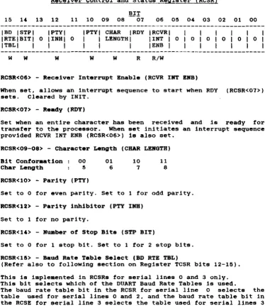
Receiver Control and Status Register (RCSR)
15 14 13 12 11 10 09 08 BI!
07 06 05 04 03 02 01 00 27
IBD ISTPI IPTYI IPTYI CHAR IRDY I RCVRI I I I I I I
IRTEIBITI 0 IINHI 0 I I LENGTH I lINT I 0 I 0 I 0 I 0 I 0 I 0 I
ITBLI I I I I I I IENB I I I I I I I
w W W W W R R/W
RCSR<06> - Receiver Interrupt Enable (RCVR INT ENB)
When set, allows an interrupt sequence to start when ROY (RCSR<07» sets. Cleared by INIT.
RCSR<07> - Ready (RDY)
Set when an entire character has been received and is ready for transfer to the processor. When set initiates an interrupt sequence provided RCVR INT ENB (RCSR<06» is also set.
RCSR<09-08> - Character Length (CHAR LENGTH)
Bit Conformation 00 01 10 11
Char Length 5 6 7 8
RCSR<10> - Parity (PTY)
Set to 0 for even parity. Set to 1 for odd parity.
RCSR< 12 > - Parity inhibitor (PTY INS) Set to 1 for no parity.
RCSR<14> - Number of Stop Bits (STP BIT)
Set to 0 for 1 stop bit. Set to 1 for 2 stop bits. RCSR<15> - Baud Rate Table Select (BD RTE TBL)
(Refer also to following section on Register TCSR bits 12-15). This is implemented in RCSRs for serial lines 0 and 3 only. This bit selects which of the DUART Baud Rate Tables is used.
The baud rate table bit in the RCSR for serial line 0 selects the table used for serial lines 0 and 2, and the baud rate table bit in the RCSE for serial line 3 selects the table used for serial lines 3 and 1.
[image:35.420.22.396.57.488.2]Receiver Data Buffer Register (RBUF) BIT
15 14 13 12 11 10 09 08 07 06 05 04 03 02 01 00 I ERROR I OR IFR IPARI
I IERRIERRIERRI
R R R R
RBUF<00-07> - RECEIVED DATA
RECEIVED DATA
R
These bits hold the character just read. If less than eight are selected, then the buffer is right-justified into the significant bit positions. In this case, the higher or unused are read as zeros. Not cleared by INIT.
RBUF<12> - Parity Error (PAR ERR)
bits least bits
When set, indicates that parity received does not agree with the expected parity. This bit is always 0 if no-parity operation is configured for the channel. Cleared by INIT.
RBUF<13> - Framing Error (PR ERR)
When set indicates that the character read had no valid stop bit. Cleared by INIT.
RBUF<14> - OVerrun Error (OR ERR)
When set, indicates that the reading of the previously received character was not complemented (RCVR DONE RCSR<07> not cleared) prior to receiving a new character. Cleared by INIT.
RBUP<l~> - Error Condition (ERROR)
WEBSTER COMPUTER CORPORATION PCLV11-J Multifunction Unit
Transmit Control and Status R~is!~~-1!CSR)
15 l ' 13 12 11 10 09 08 IPBRIPBRIPBRIPBRIPBRI
ISELISELISELISELISELI I 3 I 2 I 1 I 0 IENBI
W W W W W
07 06 05 0' 03 02 IXMITIXMITI
IRDY I INT I I IENB I
R R/W
TCSR<OO> - Transmit Break (XMIT BREAK)
When set. this bit transmits a continuous space to the
device. Cleared by INIT. When not set, normal
transmission can occur. This bit is not implemented for which is usually configured as the console.
TCSR<06> - Transmitter Interrupt Enable (XMIT INT EMB)
01
29
00
IXMIT I
I
I
I BREAK I R/W
external character line O.
When set, allows an interrupt sequence to start when XMIT ROY TCSR<07> is set. Cleared by INIT.
TCSR<07> - Transmitter Ready (XMIT ROY)
This bit is set when the transmitter buffer XBUF can accept another character. When set it initiates an interrupt sequence provided XMIT INT ENB TCSR<06> is also set.
TCSR<11> - Programmable Baud Rate Enable (PBR SEL EMB)
This bit must be set to select a new baud rate indicated by TCSR<12-15>.
TCSR<12-15> - Prograamable Baud Rate Select (PBR SEL)
BAUD RATE SELECTION TABLE
PBR Bit DLVII/E/F PCLV11 ucode V.1 PCLV11 ucode >-V.2
15 14 13 12 RCSR15=0 RCSR15=1 RCSR15~0 RCSR15=1
0 0 0 0 50 50 75 50 75
0 0 0 1 75 110 110 50 75
0 0 1 0 110 134.5 134.5 110 110
0 0 1 1 134.5 200 150 134.5 134.5
0 1 0 0 150 300 300 200 150
0 1 0 1 300 600 600 300 300
0 1 1 0 600 1200 1200 600 600
0 1 1 1 1200 1050 2000 1200 1200
1 0 0 0 1800 2400 2400 1200 1200
1 0 0 1 2000 4800 4800 1050 2000
1 0 1 0 2400 7200 1800 2400 2400
1 0 1 1 3600 9600 9600 2400 2400
1 1 0 0 4800 38400 19200 4800 4800
1 1 0 1 7200 NIU NIU 7200 1800
1 1 1 0 9600 R/U N/U 9600 9600
1 1 1 1 19200 N/U NIU 38400 19200
---
---o
=
program bit cleared 1=
program bit set NIU .. Not UsedTransmit Data Buffer~ister {TBUFI
15 14 13 12 11 10 09 08 07 06 05 04 03 02 01 00
o
o
o
o
o
o
o
01 TRANSMITTER DATA BUFFERw
TBUP<00-07> - TRANSMITTER DATA BUPPER
WEBSTER COMPUTER CORPORATION PCLVII-J Multifunction Unit
Serial Line Configuration
31
The PCLV11-J module provides tour RS232 DLVJ1-compat1ble serial line ports, one of which may be configured as the console. The programming requirements are identical for each port. Thus there 1s a total ot 16 device registers (four per line) within this component
ot the MFU. Of these, t h e ' pairs ot control and status registers (RCSR and TCSR) are used to configure the ports. The high bytes of both these registers are used for the programmable Communications Characteristics function. The actual bit values were detailed in the previous pages. To illustrate this, consider the tollowing examples: (Note that we will use the convention of programming the Receive CSR with a high-byte write (as it won't respond to a word write), and the transmit CSR with a word-write).
a) Required: Line 0- 9600 Baud, 8 data-bits, No parity, 1 Stop bit (format: 9600 8N1)
Assuming a Version 2 or greater MFU, the high-byte value for the TCSR is 11101000. This gives a word value of 160000. The value for the RCSR is 00010011, or 23 octal. Combining these two words gives a "configuration word" of 160023.
b) Required: Line 1- 300 1E2. 0101100001000011 = 054103 c) Required: Line 2- 19200 8N1 1111100010010011
=
174223.Note that in this case, the required baud rate is in the RCSR15=1 column of the table, and thus the high (200) bit of the lower byte must be set:.
d) Required: Line 3- 9600 8N1 1110100000010011 = 160023
Configuration Hierarchy
1. The bootstrap PROM contains a table of default serial line configuration parameters in the last 4 words (8 bytes). These are in the exact format detailed in the previous examples, i.e. for 300 7E2 the word 054103 would be stored.
2. The bootstrap program in the EPROM also has the capability of using the console's Answerback Message for the line configuration function. See Appendix A for details on this.
WEBSTER COMPUTER CORPORATION PCLVI1-J Multifunction Unit
4.3 Bootstrap Progr . . . ing
Page Control Regi~ter (PCR)
BIT
15 14 13 12 11 10 09 08 07 06 05 04 03 02 01 00
IDIAGI ILED&I IBANKI ISEL I
R/W
IPSHIPSHIPSHIPSHI 0 I 3 I 2 I 1 I 0 I
I I I I I
I
I
I
I
I
R/W R/W R/W R/W
o
o
o
IPSLIPSLIPSLIPSLII
3I
2I
1101
I I I I I I I I I I
R/W R/W R/W R/W 33
This register comprises byte-addressable and can Select bit determines which currently selected.
two 8-bit bytes, is
be read from or written to. one of the two 8K banks of the
word- or
The Bank PROM is The low 4 bits of each byte are used to select a page between 0 and 15 (depending on the bit value) in one of two different places in the boot PROM (depending on the bus address). As each page comprises 256 bytes, this gives a total boot capacity of
2 x 256 x 16 x 2 = 16384 bytes.
PCR<00-03> - Page Select Low (PSLO to PSL3)
These bits select one of 16 256-byte pages in the boot PROM. The selected page is then accessible through boot locations 173000
-173377 .
PCR<08-11> - Page Select High (PSHO to PSH3)
These bits also select one of 16 256-byte pages in the boot PROM. However, the selected page is then accessible through the higher boot locations 173400 - 173777.
PCR<1~> - Diagnostic LED (DIAO LED) - Bank Select <BANK SEL)
Setting this bit causes the diagnostic LED to light.
WEBSTER COMPUTER CORPORATION PCLVll-3 Multifunction Unit
CHAPTER 5
PCLV11-3 Functional Deacription
34
This section describes the general operation of each principal section of the PCLV11.
5.1 Syatem Clock Generator
Two clock signals SYSCLK (7.3728 MHz) and BCLK (3.6846 MHz)are generated by the 74LS321 oscillator chip at 02. BCLK is used by the two dual uarts (DUARTS) to generate the various transmit and receive baud rates. SYSCLK is used by the microprogrammed sequencer to step through the instructions in sequence.
5.2 Microprograamed Sequencer
The heart of the sequencer is the Next Address PROM at G5. This PROM, like all the others in the sequencer, is a 512 x 8 fusible link PROM with an output register. The function of this PROM is to produce, . at each positive edge of SYSCLK, the address of the next step of the routine currently being executed. The output from this PROM is the next address bus uAl - uA8, which, combined with uAO, connects back to the inputs of the same PROM, so that at all times the PROM is using the current value of the next address bus to look up the next value to be placed on this bus.
The least significant bit of this bus, uAO, can be made to assume the state of anyone of the 22 system signals which are connected to the inputs of the 8 input multiplexers K3, K4 and 34. These multiplexers are under the control of the sequencer, so that at any step of a sequence, anyone of the 22 inputs to these chips can be connected to uAO, causing the next address to be conditionally odd or even, based on the selected input. This mechanism allows the sequencer to make decisions based on various system states, including Tape Data Alarm and ALU zero, and then take the appropriate action. A permanently high input and a permanently low input to K4 allow for the more common situation where no conditional test is required.
PROM takes control and steps through to the end of the sequence. At this point the P PROM is re-enabled by the TRAP/ signal so that a new routine may be initiated.
5.3 Data Flow
Eight of the P PROM inputs are derived from Qbus signals so that the P PROM can recognise data transfer requests from the Qbus and initiate the appropriate microcode sequence to handle the request.
As an example, assume that the LSI-11 reads the Console Receiver Status Register in the PCLVll. First, the address of the Console RCSR appears on the Qbus data and address lines BDALOL - BDAL15L. The W PROM at C6 decodes DAL3 - DAL12 and RBS7, and produces a four - bit output corresponding to the device being addressed. In the case of an access to the Console RCSR, the output is the number 11 Octal. This number, together with DALO - DAL2 is clocked into the 74LS374 at 35 by RSYNC. On receipt of BDINL, J5 will be enabled to drive the P PROM by the RDIN signal synchronized with the system clock by K5. The P PROM determines from these signals that either the Console CSR (device 11) or the Boot Prom (device 10) is being accessed, and prompts a microcode routine to handle the request. The ambiguity Is resolved by the microcode routine, which examines the LSB of the device number. using the 10 input to 34, and branches accordingly. This routine first loads register E2 from the data bus using the PAGE/ signal. The signals LINADO and LINADl select the appropriate half of the appropriate DUART for the Console operation. It then falls into -a common routine (used by all 4 RCSRs) and has to choose between the options of DIN, DOUT, DOUTB lo-byte and DOUTB hi-byte. For this case (DIN) the routine extracts the RIE bit from bit S of register 10 in the RALU, and then reads the selected OUART using the RDN/! signal to get the RROY bit. This data, after appropriate manipulation, is loaded into the Qbus transceivers 07 and C7 by the signal LDBRL/. Zero is loaded into B7 and A7 by LOBRM/ to complete the RCSR image.
WEBSTER COMPUTER CORPORATION PCLVII-J Multifunction Unit
0.4 Arithaetic Logic Unit (ALU)
36
The 8-bit ALU, consisting of the two 2901C bit slice chips A4 and B4, is used primarily for emulating the register sets of the PCLVII - in particular 4 sets of RSCR, RBUF, TCSR and TBUF registers for each of the serial lines, as well as registers MTCSR, MTHC, MTBA and MTBAX for the Cartridge controller, and the Boot PROM PCR. An image of all of these is maintained in internal storage in the ALU. It is updated when written to by the LSI-II or by other events such as the Magtape or Duarts becoming ready.
0.0 Line Addressing
The ALU also maintains a pointer which is used by a microcode routine to scan each DUART in succession. looking for a change in status. The contents of this pointer are loaded by the PAGE/ signal into the a-bit latch at E2. The two low order outputs of this latch, LINADO and LINADI determine which channel of which DUART is to be accessed.
0.6 Interrupt Logic
5.1 RS232 Interface
The four RS232 serial data inputs. RXO - RX3. are received by the RS232 receive chip A2. The outputs of this chip are connected directly to the receive inputs of the DUARTS RO - R3. Within each
DUART there are two separate channels operating entirely
independently. Each channel converts incoming serial data into 8-bit bytes. which are then referred to an internal 4-character SILO. When requested by the LSI-li reading one of the four receive buffer addresses. the output of the appropriate one of these 4 SILOs is enabled onto the Data bus DO - D7. From here the characters, along with a status byte containing the Data Valid. Overrun. Framing and Parity Error bits. are transferred to the Qbus.
Serial transmit data from the DUARTs is buffered by the RS232 driver chip Al to become TXO - TX3. These RS232 drivers consist of NAND gates which are selectively enabled/disabled by the outputs of the upper half of latch E2. Under sequencer control. this latch reflects the state of the Break Control bits as written into the Transmit Control and Status Register (TCSR).
5.8 Cartridge Tape Interface
An a-bit, bi-directional bus, HBO- to HB7-, is used to transfer all cartridge data. commands and status information.
When the control signal DIR- is high. data flows from the PCLV11-J to the cartridge drive via the octal latch at F2. When DIR- is low. data flow is in the opposite direction via the octal buffer at 02. Data transfer is controlled by a handshake protocol implemented by the signals XFER- and ACK-.
WEBSTER COMPUTER CORPORATION
PCLVII-J Multifunction Unit 38
An alternate form of the REQ- signal is generated by pin 10 of J3, and is used in the transfer of status bytes from the drive to the PCLVII-J during a Read Status command.
Pin 6 of J3 generates the RST- signal which causes a power-up reset to occur in the drive.
DEC, DZll,DZV11,Qbus,UNIBUS,H3271 MicroVAX and MICRO/PDP-II are trademarks of
CIlAP'I'ER b
CIRCUIT DIAGRAMS
SWTSH AK2 O---+-iH ~-=)
____
RWTIT IDAl21l Bfl c>--- 290&IDAl20lIEI C>-
-D7
DL 06 D4
LOBRH/_
IU5EN/_
IDAlI5lIV2o- _ _
mt:ftm~
__ _
IOAU2l 152<>-_ _ _
OL~
~t-DL.~~ lOIR"L~
IOAlIll IR2<>---_T_ aOAllOl 1P2c>
~
+
~~mt ~M~~ ~t~
g!=-+
~ OL_ O'--~_ 2908A7
_JERR DALIS DA1I4 -::m:~IDU71 112 0----~-
-is"
~~mm
m~-___ 2908IOAl4l IH2o--~_._
OL __ OL
~~-LD&RLL.
IOAl3l If2 <>_~
IDAl2l IU
cr----IDAlll AV2 0 . -IOAlOl AU2 cr---~-,
Dl~
1
gt=±::
°Lt-r-·~~R5YN[ I ROIN a5YNU A12 C>.~ BBl8 -RODUT IDINl .H2 o---~--~_qL I _ _ RRPlY
151 ' l ' F 1 S Y N [ IODUTl AU ()--~----"J Cj _~_.--=10IN
n ro~T
mm Af2 <>---~-~_: ~ 1RPlY
WEBSTER
COMPUTER
CORPORATION
39
1157__ -~=l
g~m 275185 OALIO _~
OAl9 R~SYNC~~_. OAll _
OA17 DAl6 OAlS DAl4 DAl3
5Y5[l."--_ _ ---,
ROIN~4l527 H6
[2. _ _
ROOUL_ m~c TDINL ..
INIL
~.-~OOUTL-t
K6~~
__- - 741500
NITl
I - - -
~-~---'pGl
---"62__
<~ 7415374 ~ToGI-~. JlAl21
~~~--.. .:...li JS :s.-:=-JlAlIl OAlO_ -"L-t~L-JOO
I
--5
4 __ ._~--""O
74lSm
lOIN -R5YNU 4=ROOUI
RSYMC
lt~~}L
Jl5YW141500
MULTI
P[LVll--J
FUNCTION UNIT
CrTICUIT DIAGRAMS
SYSUK _ _ _ _ _ _ ... _ _ _ _ _ _ _ _ ~
1K S.1.P,- oS
DMA'AId:,H 5 1HTAL _ _ ASYN(I_
[f]
MTROYI_TRAPI 19 2 _
TRAPI
741S27
~
05 SIP.., TWPI
~ mCESSI
So
70
~ 0 TONLINE
lH~
I~
J4-FRONT PANEL [DUPLER
·7~~:-J=~=--==~--=-=-=:=;;:+::===
O_~ ______________ _2 ________ _
H4-l~-6 TOOUTA ARPLY.-+++++_-j~
f]1 5 _TOlNA AWTlL
L!:!J RDDUT
PERi:~Et=ll=~~
I 00
u
10!i::j::j:+t==~ ADO_
)4-Z 5 _
13 IS 14 16 17 10 12 _ _ 11
MTA(KF ZERO ___ F? CB_ MTWP/ ___ MTONLINL-_____ K3 HTDALARH __ EX(EPTlON _ _ _ _ _
17 --~~~~~I
27S25
_ _ IUSENI
05 LOIRHI LOBRLI
[5J
_HILO OALIOEY: OAL/ _ _ _ 21 HILD
OA1I5_ OA1I4 _ _ _ DALlL _ _ OALl2 _ _ _
____ J I om_
_-'A'EI CAL! JANI OALS
E5 _JON! OAL4 _ _ _ ----10 0 TEN 1
[]
____ ..J.KI ___ 18 _______ .1:0I
--i---IS OALII.____ 6 -OALlO __OAL9__ 7415257 OALB _ _ _ _ OALL
~~~-- B6
OALO
19 21
PCLV11-J
WEBSTERCUr--IPUTER
CORPORATION
M
LJ
L T I FU NeT ION UN IT
SHEET 1 OF 4
CIRCUIT DIAGRAMS
BIACKOL AN2o~ _ _ _ _ _ _ _ _ _ _ _ _ _ _ _ _
2 X llO &S'CKL INI
Il SI.CKIL AM2 0---+-+---'~
!Bsn AP2o--_
&INITl ATlo- _
15
SOMm AR2cr--H __ ~ BBl7
F7
7 9
Pili
P2 PI-= 0
12 lACK I 10 RaS7 _IN IT
14 OH. OH'O
&OMRL ANlo--_ _ _ _ _ _ _ _ _ _ ,0M.Ol AS20-_ _ _ _ _ _ _ _ _ _
a HALTl AP I o---.!:!..o
BOCOK
_
r
190
oS
T
190HALTI BOOL _ _ _
2"'569
190
[0 _________ _
SYSClC___ ________________ _
18 __________________________ _ 17 ______________________ _
16 ___________________ _
15 __________________________ _ 14 _ _ _ _ _ _ _ _ _ _ _ _ _
Il ________ ~ ________ _
12 ______________ _
"
______
----10 _ _ _ _ _ _ _
R ________ _
il==-..::.==~
AO_ ----~t++_
:~---81=~=~:f::j~t~t+==~
'O~
DEY
1--H-+l+H--t---EK/ __ -
+-t+H-t---COr/PUTER CORPORATION f7 190 41 ·5 llO 6BO NTRI 6BO
ZII ERO
_______ 07 _________ 06 __________ 05
_____________________ 04
+-+-_+_. _____________________________ Ol
~ ______________________ 02 __________ . __________ . ______ .. ____ .. _D! _______ _ ___ _________ _ _ _____ DO
PCLV11--J
MULTI FUNCTION UNIT
CIRCUIT DIAGRAMS
11K
MTRPI
INI''--_ _ ...
IRIITL-l--l--_-,
KTDRACKl
711.500
11K 220
WE8STER
COMPUTER
CORPORATION
PCLVll-
J
MULTI FUNCTION UN IT
SHEET UF 4
42
SO WAY
CART OVE CONN All 000
WEBSTER COMPUTER cORPORATION PCLVII-J Multifunction Unit
Appendix A
Bootstrap Information
Bootstrap Program Description
43
The bootstrap program dialogue normally consists of progress and error messages. It can run in one of 2 modes - Reports On or Reports Off. If reporting is enabled, many of the tests print informative messages advising details of system configuration, testing and errors. The normal mode is Reporting Off - (no news is good news). If a test produces a serious error, i t enables reporting and then restarts the whole program; all reports will then be printed including the one that gave the error.
The functions of the V2.1. bootstrap are executed in the following
sequence:-1. Tests bank switching hardware.
2. Soft-senses V.l or V.2 uCode and sets appropriate 9608Nl default. 3. Programs MFU lines at 777560, 776500-776520 from the PROM default serial line configuration table. If the table is unblown, uses 9608Nl default.
4. Executes quick memory test below 100000, then sets SP ~ 100000. 5. Prints "MFBoot V2.1.".
6. Tests the lower 64Kb of memory. Reports and halts if error.
7. Copies a loader into RAM at 600 and runs it.
8. Copies the 16Kb bootstrap into RAM starting at 1000, performs checksum function, and runs it.
9. Sets up all of vector memory (0-776) to pOint to a trap-table so as to report any unexpected or wrong interrupts.
10. Redetermines uCode level and sets appropriate table pointers.
There are 4 current versions of MFU microcode. The bootstrap senses the differences and prints
" . 1" for V. 1 ucode ".2" for V.2 ucode
".4"
for V .• ucode ".6" for V.6 ucodewith with with with
non-DLVll/E/F-compatible Baud Rate Table. DLV11/E/F-compatible Baud Rate Table. speed-improved cartridge code.
bug fixes to V.4
11. Enables interrupt on console. In the event of a Control/C being entered the ControllC Menu will display. See next section.
13. Tests page control register (PCR), reports if failure.
14. Initializes and tests all memory management registers (only if memory management enabled).
15. Determines and prints pro?essor type, options, memory size, and
parity. I
I
"
*16. Solicits an answerback from the console. (see section on Serial Line Configuration for details on valid formats). If not valid, then uses PROM default serial line configuration table. The PROM defaults are checked, and if invalid a message is printed to that effect. If the PROM is unblown or invalid, uses 9608Nl.
*17. Checks for DY:, SC:, MS: and DU; controllers. Prints status (online or offline), and in the case of the DU: unit, the size of the disc in blocks and Mbytes, and sets the 1st. online device as the boot-device. (Note that the MS: test will not run if an MT controller is detected).
*18. Scans for all DLV type serial lines from 776500 and tests the CSR, interrupt vector and level. Scans and tests addresses 760000-760200 for SDZV11 muxs. If any duplication of interrupt vectors found, reports an error.
19. Tests all of memory above the bootstrap in RAM, up to 4Mb. If processor has parity support, then turns parity trapping on. If an error is detected, the address and data are printed and the CPU halts.
20. Tests line time clock, reports if not enabled.
21. Proceeds to boot device selected in step 17. If unable to boot from selected device (device not online or cleared by ControllC Menu), goes to the Bootstrap Menu.
WEBSTER COMPUTER CORPORATION PCLVII-J Multifunction Unit
Control/C Menu
45
Entry to this menu clears the bootstrap program's selected boot device, allowing automatic entry to the bootstrap menu when all tests have been completed.
Option 1 Reboot
Restarts the bootstrap program with full reporting enabled.
Option 2 : Diagnostic Menu
a) Serial Loopback Test. Loops all discovered DL and DZ lines to themselves and to the console to allow field maintenance testing. Upon exit, restarts bootstrap program. If section 16 (above) has been run, then the PCLVll serial lines will be set up as per that section, and the SDZVl1 lines will be set to 8 bits, no parity, 1 stop bit, with the baud rate being that assigned to PCLVll serial line no. 3. (This allows this test to be run at other than 9600 baud).
b) Memory Test. Continuously run memory test. bootstrap program.
Upon exit, restarts
c) Halt. Halts the CPU. This is useful for maintenance in machined which have the halt-on-break option disabled.
d) WOMBAT Disc Test. Calls a Webster field maintenance Utility resident within the disc controller. You must re-boot system to exit. Refer to the SRQD11 manual for instructions.
e) Computer I/O Map. Prints out a list of all responding addresses in the I/O page area, together with a "best guess" of what each range is. Note however, certain disc controllers with on-board "imitation" Bootstraps assume a read of their bootstrap addresses means a request to boot. They will thus read the 1st sector on the disc into memory at location zero, and will totally wreck the running program (this one). If this test crashes on your system, then don't run it.
Option 3 - Bootstrap Menu
Allows manual selection of device from which to boot. The menu with a list of possible devices, together with their default an indication as to whether any device is responding to that The format of a legal response is
:-ddn<CR> or ddn@XXXXXX<CR>
prompts CSRs, and address.
Option " - Bootstrap Test Exclusion
The operator may exclude any bootstrap tests (see section below). Upon exit bootstrap program recommences.
Note: Entry of any character to the -C Menu prompt other than 1 to 4 will exit from the menu and resume the interrupted operation.
Exclusion Byte
Because of the (remote) possibility of particular tests in the bootstrap interfering with particular hardware configurations, the Exclusion option in the Control C Menu may be implemented. This allows particular tests to be bypassed if they are found to cause trouble. As a slightly more permanent solution, the Exclusion Byte is implemented on the EPROM at address 37760 (20 octal addresses from the end). A bit value of 1 enables the test, while 0 disables it. Thus the PROM is overblowable.
The currently assigned bit values are
1 AN Exclude serial line configuration
from Answerback Message
2 DL Exclude DL serial line tests
"
DZ Exclude DZ serial line tests10 SC Exclude cartridge tape check
20 MS Exclude MS magtape check
40 DY Exclude RX02 floppy disc check
100 DU Exclude SRQD11 Winchester disc check
WEBSTER COMPUTER CORPORATION PCLV11-J Multifunction Unit
Serial LIne Configuration
47
The bootstrap EPROM contains a table of default serial line configuration parameters in the last 4 words (S bytes). These are in the exact format detailed in the examples in "Serial Line Configuration" in section 4.2., i.e. for 300 7E2 the word 054103 would be stored.
The bootstrap program in the EPROM also contains the capability of using the console's Answerback Message for the line configuration function. The Bootstrap program copies the values from this default serial line configuration table into the appropriate registers to initialize the ports. If the above table is not entered in the PROM, (normal state as supplied by Websters), then the bootstrap program recognizes the unburnt content (all ones) and supplies the appropriate registers with the bootstrap default values for 9600 SN1. If the values in the table are determined invalid by the bootstrap program an error message is displayed and the appropriate registers are supplied with the bootstrap default values for 9600 SN!.
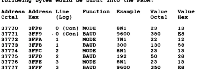
For example, to set up the values specified in the previous example, the following bytes would be burnt into the PROM:
Address Address Line Function Example Value Value
Octal Hex (Log) Octal Hex
37770 3FFe 0 (con) MODE 8N1 23 13
37771 3FF9 ·0 (Can) BAUD 9600 350 ES
37772 3FFA 1 MODE 7Nl 22 12
37773 3FFB 1 BAUD 300 130 58
37774 3FFC 2 MODE SNl 23 13
37775 3FFD 2 BAUD 192 50 2S
37776 3FFE 3 MODE SNl 23 13
37777 3FFF 3 BAUD 9600 350 ES
[image:61.419.43.366.255.373.2]butted up against each other setting lines I, 2, and respectively would cause <1208NI1927EI300702>.
to
3
the
make the message. For example, to 1200 8NI, 19200 7El and 300 702 Answerback Message to appear as
Note that there are four possible addressing configurations for the serial lines. Base address at 777600 or 777640 and console either enabled or disabled. The physical lines will be programaed as tollo_:
Address Physical Logical bbbnps Group
777560 Console always 9600 8Nl
776500 1 1
776510 2 2
776520 3 3
776530 4 3
116540 5 1
776550 6 2
116560 7 3