c
o
HONEYWELL PRODUCT LINE
The following communication support is currently available for the models listed below.
1. 2. 3. 4. 5. 6. 7. 8. 9.
a. 2780/3780 Asynchronous - Honeywell to Honeywell only
b. 2780/3780 BiSynchronous
c. UltiLink - File / Acct. cre~tion - Remote Asynch.
d. UltiNet - Distributed Processing - Remote Logical Disk / File Sharing.
e. Auto Dial - 8 way board only
note: Racal Vadic 2400 Synchronous modem will allow Auto Dial with 16 way board, although i t is currently not a Ultimate supported option.
f. Pass-Thru - I/O Redirection
Model 6000
Model 6010
Model 6210
Model 6410
Model 6600
Model 6800
Model 7000
Model 7200
Model 7400
The Honeywell 1400 series currently supports the following:
a. UltiLink - File / Acct. Creation - Remote Asynch.
C
"OJI
f
C
VAX PRODUCT LINE
No Ultimate supplied communications software is currently available on the following models.
1- Model 8100 (MicroVAX-II) 2. Model 8200 (VAX 8200)
3. Model 8500 (VAX 8200
,
8550) 4. Model 8750 (VAX 750)5. Model 8780 (VAX 780) 6. Model 8785 (VAX 785) 7. Model 8800 (VAX 8800)
8. Model 8860 (VAX 8600
,
8650)DEC PRODUCT LINE
The following communication support is currently available for the models listed below.
1-2. 3. 4. 5. 6. 7. 8.
a. 2780/3780 BiSynchronous
b. UltiNet - Distributed Processing - Remote Logical Disk / File Sharing
c. UltiLink - File / Acct. Creation - Remote Asynch d. Pass-Thru - I/O Redirection
Model 1500 9. Model 3020
Model 1510 10. Model 3025
Model 1520 11. Model 3030
Model 1525 12. Model 3040
ZBM HARDWARE CONCEPTS
o
c
o
o
CHANNELS FOR HOST COMMUNICATION
- Ch_~~~~ p~~~~ _ _ ~~ £~~~_ H~_t t~
-CONTROL UNXTS AND PERXPHERALS
R . . g'U~.t.eo H C:::UB t . _ ~ d
d . t . . £~~W b~t.w~~~
P . . ~iph . . ~_~ d~vic . .
- B'U£:£ . . ~ d _ t . .
- C~~ h.~d~.. ~u~t.ip~EP dEPvicEP_
c~~cu~~ . . ~t.~y
i _ eo_
- - - - " " - - - " "
-COMMUN~CAT~ON CONTROL UN~T
o
o
*
L~~_~ ~~~t~~~ d~~i~~ ~h1Chp~~~id~ H~_t _~c~__ t~
~~~~t~~y _tt_~h~d t~~~in_~ _
_ ~d ~~~ot~ 3 2 7 4 C~~t~~~ U n i t _
*
C~~~~~ic_t~ ~ith H o _ t o~~~"ch_~~ . . ~"
E_t_b~i_h a n d
C~~~~~1c_t1~n_
~"T11~tE!" c:f~~1~"1!!iI C~~tZ""~~ U~1t. . . .
* 3 7 0 4
* 3 7 0 5
* 3 7 2 5
cC)nt.Z""~~ _~~
~ith
t.he-a.~c:f Z"""T11~t.E'
,~---~---ZBM SOFTWARE CONCEPTS
o
- Ac=c= . . . _ M . . thc:::»cf_
(/
o
~----.---o
(/
o
OPERATXNG SYSTEMS
~ P~~g~_~_ t h a t _~h~du~~ / _up~~~~_~
~~~k, ~a~_g~ c~~put~ng ~~_~u~~~_,
a n d ~p~~_t~ / c~nt~o~ P~r~ph~ra~
c:f . . ~~c . . _
~ MVS
E _ c h .j~b ~r
t~ .1.6 MB ~£
u . . . r ~_y h_~.. u p
VM _c:fc:fr . . _ _ _p_~
..
~ VM / 3 7 0
u_~r h _ _ t h . . ..qu~~_~ . . n t
(
c'
ACCESS METHODS
- A _ _ i _ t . . th~ p~~g~~~m~~ i~ ~~~~~d t~~~_£~~ b~t~~~~ x / a d~vi~~_.
-E_~h a s ~£ d_tEll
Me!'th~d
n i q u . . . .
p~~vid . . _ _~v . . ~a~ ~~th~d_
~~g_~i~_ti~n_ Ea~h A~~e!' _ _
p~~vid~_ ~n~ ~~ m~~~ t . . ~h
~£ £i~e!' ~~~ati~n/~ . . t~i . . v_~.
A~~ . . _ _ Me!'th~d_ t h a t inv~~v.. d a t a ~~~~uni~ati~n_ ~~nt~~~ di~ . . ~t t h . . t~an_mi _ _ i~n ~£ d a t a b . . t~ . . ~n thE!!'
H~_t app~i~ati~~ p~~g~ama~d ~ . . ~~t . . t . . ~~ina~ __
VTAM
- Supp~~t_ a ~id.. va~i . . t y ~£
d . . vi~ . . __
-
F~ . . :xib~.. _ _~u~tip~int
tc:::J t . . ~~ina~
~in"&J.
- P~~vide!'_ £~~ ~~~.. di~~~t p~~g~a~
~~~t~~~ ~£ t . . ~~ina~_.
- D . . _ig~ . . d t~ u _ . . n . . ~ ha~d~_~.. a n d _~£t~_~.. _u~h a&ll VS a n d SNA. Wh . . n u&J . . d ~ith 3704,3705,~~ 3 7 2 5 CCU'&J, VTAM _~~c:::J~_te!'_ _~~.. ~£ t h . . ne!'t~~~k ~gmt_ t~ thE!!' CCU, £~ . . . . i n g u p t h . .
o
~
('
COMMUNZCATZON PROTOCOLS
. . r..v.::L::r:-Oll'l"r..t..
ZBM ' U " " . t . h . . :fo::r:- t. . . ::r:-lI'I.::Lr..a~
EBCOZC ~ha::r:-_~t.e!"::r:
opea::r:-at..::Lor..liB.
_ . . t.
( O L e )
~ S~t o £ ::r:-'U~e!"_ t . h a t . . . r.._u::r:-~ t.::r:ar.. . . -lI'I.::L _ _ .::Lor.. ayr..~h::r:-or...::L~at..::Lon ar..d
~
. . ::r:-::r:-o::r:--:f::r:- . . ~ d a t . a ~oll'lll'l'Un.::L~at..::Lor.. . . .
P::r:-ov.::Ld.... :fo::r:- t . h . . o : f d a t a :f::r:-Oll'l or..e!" I ! l r.. 0 t. h . . ::r:- •
o::r:-dE!"::r:-~y t.an_:f . .
::r:-~o~at.::Lon t . o
~ F.::L::r:-at. OLC t . o haVE!" lI'I'U~t.::Lp~ . . d . . v.::L~.. add::r:- . . . . _.::Lng.
- X~d~p~~d~~c~ ~£ c~d~ _t~~ct~~~
SOLC ~_~_ ~~~y ~~~ ct~~ ch~~_,
FLAG,BSC ~_~ _~v~~~~,c~~p~i
c_ti~g c~d~ d~t~cti~~ _~d ch~ck:i~g_
- B i t _~~i_~ _y~ch~~~~~_ t~_~_ ~i _ _ i~~_Eith~~ ~~d~~ ~~ CCU p~~vid~_ b i t _y~ch~~~i~_ti~~_
- H_~£/£~~~ d~p~~~,p~i~t t~
p~i~t,~~~tip~i~t,~~ ~~~p
c~~£ig~~_ti~~ __
-
SOLC c~~~t_ t~~ _~p~~_t~_~q~~~c~_ ~£ £~_~~ __ Th~
£~_~~ b~i~g t~_~_~itt~d, _~d th~ £~a~~ i t ~~p~ct_
t~ ~~c~iv~ ~~~t_Thi _ _ ~~~~_
SOLC ~i~k_ t~ h_~d~~ _~~d
_~d ~~c~iv~ d a t a i~d~p~~
o
(.
o
SYSTEMS NETWORK ARCH%TECTURE
Supp~~t~ng _t~u~tu~~ £~~
v~d~_ _ £~_m~~~~k w~th~n
SDLC.P~o wh~~h
u_~~_ ~_n v~~~ ~omp~~~ ~ommun~~_ t~on_-b _ _ ~d ~omput~~ _y_t~m_
w~th-o u t ~on~~~n £o~ th~ phy_~~_~ d~
t_~~_ _ _ t o ho~ _ _p~~~£~~ n~tw~~k
~_ o~g_n~:z: . . d .
*
Sh~£t_ £un~t~on_ £o~m . . ~~y p . . ~£o~m~db y t h . . H o s t t~ t h . . n . . t~~~k
£un~t~on_ _u~h _ s d . . ~~~.. ~ont~o~,
d a t _ £o~m_tt~ng,_nd ~ommun~~_t~on_
~~n . . m _ n _ g . . m . . n t .
B _ _ . . d o n _ . . . t o £ w . . ~~ d~£~n . . d
~og~~_~ ~_y~~_.Ch_ng . . _ ~_n b . .
m_d . . ~n on~ 1 _ y . . ~ w~th~ut _ £ -£ . . ~t~ng ~th . . ~ ~_y . . ~_.%nt . . ~_~
t~~n ~_n o~~u~ b . . t w . . . . n £un~
t~~n_~~y p_~~ . . d 1 _ y . . ~_ ~n d~£
-c
p~~£~~~_ _pp~i~_ti~~ p~~~~ _ _ i~g.
D~~_ ~~t b~~~~~ i~~~~~~d ~ith
~~~ti~g ~£ d a t a ~~ p~~t~~~~_.
F~~~t.:1..~~_~
C~~t~~~~~d b y th~ ~pp~i~_ti~~ ~_y~~.A~~~~_ ~~~~~~i~_ti~~_
b~t~~~~ .pp~i~_ti~~_ ~~ _~.:1..t~h i~g b~t~~~~ _pp~i~_ti~~_.
C~~~~~~~d ~ith r~~ti~g _~d ~~~~
~~~t ~£ d_t~ b~t~~~~ d~~i~~_.
A~~~w_ SNA t~ b~ i~d~p~~d~~t ~£
~~tw~~k t~p~~~gYJ~~~£ig~~~ti~~ ~h_~g~_ i~ ~~tw~~k ~a~ ~~~~r with~~t ~h~~g~_ i~ d~~i~~_.It
_~_~ _~~~w_ ~~tw~rk p a t h _ t~ b~
o
o
o
D i G i T A L NETWORK ARCHiTECTURE (DNA)
- F~~~~~~~k £~~ a~~ Digita~ ~~~~~ni
c::::at.i~n p~~C::[~c::::t.s.
(
NETWORKING PRODUCT L I N E
- DECnE!'t.
- Ir:atE!':r-r:aE!'t
- P~c::::kE!'tr:aE!'t
t.~ IBM ~r:ad ~thE!':r- ~E!'r:ad~:r-~
(Wan.g~CDC~UNIX~Ur:a~~a~>
Digita~ t.~ Dig~t~~ ~~a X . 2 5 PSDN
o
o
DECNET MAJOR PRODUCT C A P A B I L I T I E S
- R~~~t~ ~~~~~~d/b_t~h £i~~ ~~b~i _ _ i~~
o
o
INTERNET MA30R PRODUCT C A P A B I L I T I E S
~ Digit_~ t~ IBM C~~~uni~_ti~n_ S~£tw_~~ ~££~~_ _~~vi~~_ t h a t
~_ng~ £~~~ int~~~~nn~~ti~n ~f
th~ DNA a n d SNA t~ _ing~~ £un~
ti~n,_y_t~~ t~ _y_t~~ p~~t~~~~
. . tnu~_ti~n_
P~~vid~_ int~~~~nn~~ti~n ~f
Digit&~ a n d IBM ~nvi~~n~~nt_
~n _ n~tw~~k t~ n~tw~~k ~~v~~.
VMS ~~ Mi~~~VMS _y_t~tn_ ~n _
DECn~t n~tw~~k ~_n _~~~__
~~-_~u~~~_, p~~g~atn_, a n d in£~~ ~&ti~n w i t h i n a SNA n~tw~~k_
3 2 7 0 ~_~~_ w i t h i n _ SNA n~tw~~k ~_n a~~~__ DECn~t b _ _ ~d VMS ~~
Mi~~~VMS _y_t~~ ~~_~~~~~_ w i t h i n
_ DNA ~nvi~~n~~nt_
~ VMS./SNA
Si~i~_~ t~ DECn~t'/SNA b u t £~~ i n
-_t_~~&ti~n_ t h a t ~~qui~~ a _ing~~
di~~~t ~ink t~ th~ SNA ~nvi~~n~~nt
0-o
P:X-ClV'ic:l.. pCli~t. t.C) c::_t.iC)~ "1'nu~ . . t.iC)~
. . ~c:I IBM . . y_t."1'n&il.
pClirl.t. C::Cl1'n1'nu~i
b . . t.'W . . . . rl. Dig:Lt.&a~
D . . _ig~ . . c:I t.CI _ _ t.i&l£Y
t . i C ) n Digit._~ t.CI IBM
:x- . . qui:X-"1'n . . ~t.&I.
- :::3271
- 2 7 8 0 / : 3 7 8 0
o
(-)
0··'
.-ETHERNET OVERVIEW
(LAN)
A p~i~_t~~y ~~~~d d a t a c~~~u~ic_ ti~~ _y_t_~~~~~~~_ high-_p~~d c~~ ~u~ic_ti~~ ch_~~e~_ ~pti~iz~d £~r c~~~~cti~g i~£~~~_ti~~ p~~c~ _ _ i~g ~quip~~~t.Th~ g~~gr_phic _r~_ i _
u_u_~~y ~i~it~d t~ _ _~ctio~ o £ _
bui~di~g~_n ~nti~_ bui~di~g~or _
c~u_t~~ ~~ bui~di~g __
L A N ' _ pr~~id~ a £ _ _ t~_£~ici~~t
~_an_ ~£ _xcha~gi~g i~£~r~_tio~.
R _ _ ~u~c_ sh_~i~g _~~o~_ u s _ r s t o _ h a r e _xp~n_i~_ p~riph_r_~ d_~ic _ _
_ ~d d _ t _ b _ _ _ _ •
LAN' • • xp_~d t h . p o _ _ ibi~iti _ _ £~r
g~~b_~ r _ _ ~u~c_ _h_ri~g b y ~££_r i n g _t_~d_rd_ £~r c~~~unic_ti~~ b.t~_~~ di££_r_~t ~_~dor_ a~d b e
-t~~~~ ~~c_~ _~d ~~~~t_ ~_t~~rk_.
---".---.-~---o
o
... B:Z-C»lIlelb_nel
Cc::::t.t. .,.:f:f.,.c::st.:L'V . . eI_t._,'Vc»:Lc::s . . , _ n e l
b~ . . .
... B _ _ . . b_~eI
t.:z-an_pc::::t:z-t. Tn . . eI:L_ 'V:Lc:f . . c::::t C»~ . h _ : z - . . eI
:f c»:z-
C'Ja-... U_~eI :fc»:Z- C::SC»TnTnU~:LC'J_t.~c::::tn_ b~t.~~~~
:f~c»c»:z-_ a n e l bu:L~c:f:Lng __
Th:LnW:L:z-e- CC»&l:x:L_~
... U_~eI t.c» c::sc»n~ . . C'Jt. ~c»:z-k_t._t.:Lc::::t~_, PC'_,_~eI ~c::::tw-. . ~c:f _y_t.~Tn_ :Ln
(
I Bt1
Communi cat·
__ lODS
Overview
Topics
General Overy jew
• Origins
• Protocols
• VM Internal Facilllties
• Hardware
• Software
(-Adyanced Program to Program Communication
SNA Technical Overview
(
VM Spoo 1 ed Dev 1 ces
Virtual
Machine
---_
...
(Reader
I
/
-
.... (
Punch
I
~
PrInter
CP
Spool
User 1
-'(punCh
I
Cp
/
.J'
User 2
(
:::0
tf)
n
(J)
:0
(fJ
n
(fJ
::c
(JJ
:::0
:::0
n
'-
c...
CJ)
m
m
(
CD ~ a.
c
"a.
.,
.;-c a.
.,
in ;:,
_.
a..,
.,
a.(
(
"'\
/ ' 0z
-.
n ~"
:::I ::1<
<T)Flle
Transfer
Format
Header
Memo
Data
Trailer
Pierre,
How are the projects
dotng. Let me know tf you ...
~
Joe
DCA/RFT
Memo
From Card Images To ...
Cards
~
NJE Flle
NJE Header
Header
Card
Data
Trailer
NJE Trailer
Communi cat ions
I IProtoco 1 s"
Asynchronous
- IBM Half Duplex
- Ultimate Series/l
Binary Synchronous
Channel to Channel Adapter
Systems Network Architecture
(
- Synchronous Data Link Control
- Channel to Channel Adapter
- X.25
- Token Ring
- Ethernet
TCP/IP
VM Constructs
Enhancements of Rea 1 Hardware
Spooled Devices
Virtual Channel to Channel Adapter
Loglca 1 Devices
(
Software Only
Vlrtual Machine Comunication FacUlty
(/
Hardware
Channel to Channel Adapters
270X Communication Adapters
370x Front Ends
Emulator Program
Network Control Program
Partitioned Emulator Program
(-
VM Software
I
Nat 1ve VM Support
• S j nary Synchronous - SSC
• Asynchronous - ASYNC
Remote Spool1ng and Communications Subsystem - RSCS
• S 1 nary Synchronous - SSC
• Channel to Channel Adapter - CTCA
• Systems Network Arch1 tecture - VT AM/SNA
Passthru
• S 1 nary Synchronous - SSC
• Channe 1 to Channe 1 Adapter - CTCA
(
VM Software -
II
VTAM/SNA
• Synchronous Data Link Control - SDLC
• Binary Synchronous - BSC
• Channe 1 to Channe I Adapter - CTCA
Transparent Services Access Facility - TSAF
(
• Binary Synchronous - BSC• Channe 1 to Channel Adapter - CTCA
• Inter User Communications Veh1cle - IUCV
Office Systems Architecture
• Document Interchange Architecture - DIA
• Document Content Architecture - DCA
• Distributed Office Systems Support - DISOSS
An I ntroduct i on to
Program-To-Program
Communication
(
and
Peer-to-Peer Network
i
ng
in
an
IBM SNA
(
(\
A HIERARCHICAL
SNA NETWORK
lFWS · · ... .
... .
· ... .··c····
· . · ... ..
.. ...
· .
. ... . . .. . · ... .·
... .··0····
... · .. . ... . . .. . · . . .. .· ... .
HOST
I---I::::C::::::::
5/.370
... · ... . · ... .... . . . .. · · ... . ... . · · ... . ... . · ... . · ... . · · ... . ... . ·
·
... .. ... . · .... .:::c:::::::::
· · ... . ... . · · ... . ... .·M···
.. · .... . . .. . .. · .... . . .. . · · ... . ... .··C····
· ... ... · ... . .... .
.. .... .
t - - - I
HOST
5/.370
(
(
DATABASE
I
APPLI PGMSSERVER
MASTER/SLAVE
LIMITED FUNCTION
WOR~STATION.... ---REQUES1:..---I---RESPONSE - - I ...
-SLAVE
PEER-TO-PEER
DATABASE HOST
I
APPLIPGMS
INTELLIGENT
WOR~STATIONINFORMATION
I
APPLI"'--E~)(~CH~A~N~GE~-" PGMS
- --- --
-DISTRIBUTED TRANSACTION
PROCESSING
S/370
c
o
I - - IM
c
POLIcr ISSUE -...,.-.
SYSTEM 38
PRICING'INFORHATION
PC
(
(
\./
APPL
PGMl
IWS
CONVERSATIONS
AND SESSIONS
OGICAL UN T 6.
2
CONVERSATION
. Hmmn
.~~."
...
• • • " 0
APPL
PGM2
(
(
APPC WITH
PHYSICAL UNIT 2.0
SYSTEH/370
JCICSl
~
I
sSCPI
I I
COMC
PU 2.0
LU 6.2
(~\
APPC WITH
PHYSICAL UNIT 2.1
PEER-TO-PEER NETWORKING
IWS
IWS
PU 2.1
PU 2.1
LU 6.2
...LU 6.2
SNCP
SNCP
COMC
SSCP
(
ADVANCED
PEER-TO-PEER
NETWORKING
SYSTEM/38
K.2S
S/36
S/36
S/36
SERIES/!
(
APPN NETWORK
UNDIRECTED
SEARCH
CllRISF?
NNS
NN6
CllRISF?
~
NN3
PU 2.1
APPN
DYNAMIC TOPOLOGY UPDATE
PERIPHERAL NODE
NNl
NN2
PU 2.1
(
(
..
SNADS
DSUI
~3V 1
U3EJ1.S:
R. PHISH D4
B . • ALTO. D2
L. BIRD D3
ROUTE DSU3 DS02 DS04
v
22 Il'OUTE 2<111 . . . :-::
1
. . . . . . . . .
""
DSV 3DSU3
U3EJ1.S:
2. PARISH D4
B . • ALTO. D2
L. BIRD D3
1.0urE DSUl DSU2 DS04 R2 1.2 R4
NETwoRKING
/lOUT£ I
"-IlOUTE ..",
r~~~::1
DSU2
/
DSU Z
VSQS:
t. POI. D4 B.
Wu.ro.
D2L. BDD D3
ROurE DSU3 D3Vl DSU4
11
1.3 /lOUTE .T0::U4
DSU 4
USEaS:
t. PDlS D4
B. WD.%OII DZ
L. BID D3 ROUD:
D3Vl
....
DSU2a:s
(
SNA
Technical
Pre-SNA I BM Network
IMS
Terminal
IMSBTAM
(
eles
Terminal
CICSTSO
TeAM
Terminal
TSO
JES
RTAM
Terminal
JES..
()
SNA Network
IMS
(
CICS
Terminal
V
TSO
A
T
Term1nal
M
Terminal
JES
Terminal
Other
IAppl1caHom
(.
SNA Network Structure
IBM HOST
C
°A
I T J l p
M I S E h p
S
c
0 S 8 I.local
s
r327
VTAM
110 Channels
Local
NCP
(
lBt13725 Communications
Controller
NCP
\
Remote
NCP
~~~~~3-2L71~
Remote \
-=~..-",-/·
3274s
...
-
... -
..
=
NCP3271
'-'...-:J3271
f
Single Domain Network
r
- -
-
-
- - - - -
-
- -
-,
I
T50
I
IMS
JE5
CIC5
LU LU LU LU
I
VTAM
I
I
SSCP
Subarea
.J
L
-
- - -
-
- - - -
-t
r
-
Su~e;l
rsub;;:ea-
-
-,
I
NCP
I
I
NCP
I
I
I
I
I
I
I
I
I
I
I
I
I
(f)
r
-
- (f)1
c
0-m
c
.,
I
0""I
(1)
m
OJ
....,
0
(1)0
I
m
I
::I
3
~
:;,
c:
_.
...
::)
I
<
>
I
c--t-Z
-l ~ '0...
(")
>
':: en-C
"'0
I
::I III 11\I
,..
...
o·
m
:::I:J
-
-
L
- -
~
0
0
(
3
OJ
...
-
-
...,
~- -
Z
0
<
>
I
(l)Z
'00 -l '0
~
(")
>-
r - :3
en-0
::I III lID~
!::
~ 0
I
_.
-\-
~
I
:::I0
::)
..,
I
(f)I
7'
(f)
c
c
C-
O-t
m
I
~
....,
.,
(0(1) ~
OJ
L
-
-
~
(~\
(
Concurrent -Seri a 1 Contro 1
APPLs
APPLs
VTAM
SSCPA
VTAM
SSCPB
NCPA
NCPA and NCPB
M""
ownedby --....
SSCPA and SSCPB
Link owned
by
both
SSCP A
and
SSCP B
VT AM Under VM
r--,
GCSr--,
U
I I~
I1
• •
•
C
t V LUV
LUR
M
i5
T5
5
m CA
Ca
5
M
S
t IUCV
I
Isscp
e
•
I GCS
I
I
•
•
I, 'S
I ICP
L
__
~*CCS
I/O Channe1s
PU
I
I
NCP
LU
LU
I
1
PU
PU
I
•
I
I
I
I
( 6.
Session Establishment
VSCS
A
Other
Appls.
VTAM A
... ----. 1.
SSCP
PU
LU
A
t - -...PU A ... - - -....
1. SSCP-PU Session
2.
SSCP-PU Session
3.
SSCP-PU Session
4. SSCP-LU Session
5.
SSCP-LU Session
6. LU-LU Session
PU
(-<
-
U1-
A-
VI- -
-
(f) (")t
<n't
1
~ ~
+ (")
I'T'I
I
I..,
-I
(J'Jz
c.n
I~
--i -i
(f)
r
C
r-I I I
•
II
C
I
I
.
~I
I
~
I
I
-
I
A~'"
I
I
I-
I(f)
r-(f)
C
(")
CJ)
'lJ
(1)
(J)
(
I
II
I
I
I
I
(J)
...
0
~
I
I
-I
I
+ ::l-.
~+
I
~
+
I
~
CO (J'JICh
U'J-
'0 tD0 'C
z
I
-"'0 -i 0
I
I
I
I
-~...
c-t"...
~r-t"
...
I
I
I
0
•
1
I
I
I
~ I 1
-(
... ...n
rv
<:r:
0 '-"'n3
-io
03
»(J)
::.'I c::
3~
--i
z~~
n"" _.
-0°(')
-i
'-"'
-,
- Q )
G')
-~
tD _.
"'0
~ ::.'I CJ)OJ
::J
-ICIJ
lil
~3
"\ :;
v V'
C }
-0
-"l
'"
...
-(J')
~ l
I
-i
G>
CIJ
...
--i
...0
~ ~ G') '-"' ~(
::J
(j)
...,
0
c
-c
en
--I
n
0,...
(j)<:r:
n3
~-io
03
»(1)
~ c::
3~ zr-t'::J
n"'_
~ '-"'-o°n
(\J -~ <D~ '-"'..., 0
::.'I
(
(
m
:;;0A
I
a
(J)
r+-»
:r:
0
rJ)
~
OJ
<
;;:0
o
m
;;:0
jJ
"
L
~
I
(
z
<
( )
--I
\J
J>
»
3
~---~
»
<
I
;0 ~I
(
I
\
I
I
I
I
<
;0
~
- - - -
....
z
<
( )
. --i
U
»
co
~OJ
(:
t
I
I
I
<
;0I
0
SNA Layers
(.
End User Data Sent Data Rec'd End User(
~
I
S
E
S
S
Io
N Function Mgmt. Data Services Data FlowS Control
E
R
V
I
C
E Transmission
S Control
P
-A
r---~----~T
HC
o
N
T
Ro
LS
E
R V Path Control Data Link ControlC···".'
I
C
Physical
E
S
-by
by
I
End User End User
...
-_
....
_-
...
I
FMDI
1
~...
t
Function Mgmt.• Protocols Data Services
I
I
I
I
I
I
1
-+-
DFC- +
t
~ Protocols
I
I
I
I
I
I
1
-+-
TC--+t
~ Protocols
I
I
I
I
I
I
. - PC ...
~
Protocolst
I
I
I
I
I
I
I
-+-
OLC--+
I
~
Protocolst
I
I
I
I
L..
--
-I
I
I
I
-...I
-Phys1cal L1nl<
Network Data Flow
Origin Node
Intermjdlate Node
Boundry Node
Destination Node
From End User
To End User
User
User
Data Data
parameters
FMD Services Layer
parametersI
L
RU
( L
RU
parerHten
Data Flow Control Layer
" p ... metersI
I'
;7"
RU
RU
parameters
Transmission Control Layer
parametersI
LR
RU
t R
RU
--e H H
parameters
Path Control Layer
parametersC
T R RU
TR RU
TR RU
TR RU
TR RU
TR RU
H H H H p
H H H H H H H H
Data Link Contro
ILayer
L
~
R
RU
L lIf
RRU
L L TR
RU
L L ITR RU
L L TR
RU
l L~
R
RU
LH H T H ~ H T H H H T H H H T H H H T H H T
'~
-
pI . . .
"-""
I. j
I SO Mode 1
vs.
SNA
ISO Model
SNA
Application
End-User
L lr~
?-.Presentat ion
Function Mgmt Data Svcs
Data Flow Control
Session
Transmission Control
Transport
Path Control
Network
Link
Data L ink Control
Physical
Physical
v
~t ....
The Transparent Services
Users Connect to Resources Transparently
User
A
l
User
B
Resr
Rl
...
J
Resr
R2
I
j
-TSAF
VM
CP
TSAF
VM
CP
Single VM System Example
(
APPL-X
APPL-Y
SERVR-A
RES A
r
SERVR-B
RES B
i
t
RES C
t
eMS
cMS
CMS
GCSAPPC/vM
APPC/vM
TSAF Collection Example
(
..USER
TSAF
TSAF
SERVER
RES-R
(
...
...
... ", 4/
-•
i
i
cAs
CMS
c~s
CAS
•
,
• IAPPC/VM
LAPPC/VM..J
CP
CP
(
(
TSAF Collection Detailed
TSAF
~MCRM
SI
S2
/MCRM
ATSAF
R1
R2
CMS
/(CTC.
•
TSAF RESOURCE TABLE
S1
S2
USER
SERVER
•
RESID= R1
lREQUESTER PGMI
I
I
I
I
CMS
GCS
I
t
APPC/vM
.
~HIDENT
CP
I
I
LAN
orBSC)
I R1
I
SERV
I
CP
HIDENT
APPC/vM
ACMS
GCS
CMS
!
SERVER PGM
RESID=R2
SERVER
USER
R1
S1
RZ
S2
TSAF RESOURCE TABLE
I
R2
I
SERV
i
~
.
(-LU6. 2 APPC BASE
vs.
APPC/VM
BASE
BASIC
CONVERSATION
VERBS
MAPPED
CONVERSATION
VERBS
CONTROL
OPERATOR
VERBS
APPC/VM
IMPLEMENTS
SEMANTICS
OF BASIC
CONVERSATION
APPC/VM
in Context
(-
..
(APPC SEMANTICS)
APPC/VM PROVIDES
PROTOCOL ENFORCEMENT
E.G. HALF DUPLEX
CONVERSATION MODE
FORMAT AND SESSION
PROTOCOL ENFORCEMENT
I. E.
LINE FLOHS ARE
NOT PROVIDED
PU SERVICES ARE NOT
PROVIDED
SNA DATA LINK CONTROL
IS NOT PROVIDED
LU6.2
PU
DLe
-SOLe
APPC/VM Mapping to SNA APPC
(
(-~
. /
APPC/VM
APPC Verbs
CONNECT to server
(Server RECEIVEs
ALLOCATE Datal
]
ALLOCATE
SENDDATA [RCVE=NOJ
RECEIVE
SENDCNF TYPE=NORMAL
SENDCNFD
SENDREC
SEND
ERR
[SENDCNF TYPE=SEVER J ]
SEVER (NORMALIABENDl
SEND_DATA
CONFIRM
CONFIRMED
REQUEST_TO_SEND
SEND_ERROR
DEALLOCATE
Tandem Communications Presentation
• Philosophy
• Fault-Tolerance
• Expand
• Gateways to other environments
• Integrated Fi Ie-system support
• Integrated Expand networking
I
Philosophy
• Backbone Network
• Faul
t
-Tolerance
• Gateways
• Modular Expandability
Fault-Tolerance
DYNABUS
DYNABUS
DYNABUS
DYNABUS
CPU CPU CPU CPU
MEMJRY
MEMJRY
Me.1ORYMEMORY
" 10 PROCESSOR r'-.. 10 PROCESSOR r'-.. K) PROCESSOR ~ K) PROCESSOR
(
C
:;Gateways to other environments
IBM
TERMIN
SOLe
ATM
IBM
PC
3270
EMUL
IBM
*IMS
·CICS
*TSO
IBM
*
HASP
*]ES
*
RES
Integrated File-system support
• Supports all Tandem fi Ie formats
• Key-Sequenced files
• Relative Record fi les
• Entry Sequenced
fi
les
• Unstructured
fi
les
• OS/FT
databases compatible
• Cobol
.• Pascal
• Fortran
• C
• PATHWAY
• SQL
• Supports Tandem utilities
• Backup/Restore
• FUP
(
~.-/
Integrated Expand networking
• Network
fi
les are transparent to applications
• Databases may be distributed
• Q-Pointer access to aJ I networked systems
Integrated Message-system support
(C
•
Supports the Tandem message system
Multilan support for PC-networks
• Allows attachment of PC-networks
• Modular, expandable system
• Tandem acts as server for DOS files
• PC's may access Tandem files
(
NETWORKXNG
PRODUCTLXNE
- DECn . . t.
Digit._~ t . o n o n Digit_~(DECn~t-DOS>
Digit.a.~
S l Y S l t e - T n S l
t o X~M a.~d ~t.h~~ ~endo~& (W&ng~CDC~UNXX~Uni~ac)
Digit_~ t o Digit.~~ ~ia. X . 2 5 PSDN
e
~
~
DECnet USER UTILITIES
TERMINAl-TO-TERMINAl
(PHONE)
USER-TO-USER
(MAIL)
NETWORK COMMAND TERMINALS
(SET HOST)
NETWORK FILE TRANSFER AND
(DCl)
RESOURCE ACCESS
NETWORK COMMAND PROCEDURES
(DCl. SUBMIT/REMOTE)
TERMINAL ACCESS
D I A LOG
VMS
VMS
P H 0 N E
P H 0 N E
---I
I
I
I
JI=
DI~
.,
eu
IM A I L
VMS
VMS
READ
SEND
FILE
M A I L
M A I L
REPLY
FORWARD
DELETE
DIRECTORY
DISTRIBUTION LIST
uf 05
~
l/)
~
fT1I
D
- l:c
0 l/)
aa - l
<:
~
:3~
l/)~
>:;
I I I I I I I I I I---
I I I I I I I I I I I I I ICJ
~
$
~
I I I I
:::0 fT1 :3 J>
n
-0<:
~
FILE TRANSFER
VMS
I
RMS
VMS
I
RMS
[~
-;
I
"
~$COPY
---
FAL
,
"
-D
-- COpy
-- DELETE
a
0
~
-- SUBMIT
-- APPEND
-- DIRECTORY
etc.
uf(M
~
..,
('
" " , "T'l J:>r
c:: .-, II63
"T'l""", .
...
I'D J:>n
n
I'D""
""
r
""",.""
r-+-I'D ::J I'D..,
CJ rr1 n(~ ::J
I'D
r-+-""
I'D..,
<
""",.n
I'D -0 " ) al.O
..,
III
:::3
c"
n
e::
;::0r
;::0 rr10
.-.
::pr. V'l --f CJrr1 rr1
"T'l J:>
r
0
PROGRAM -
TO -
PROGRAM
VMS / RMS
VMS / RMS
OPEN
OPEN
READ
READ
---WRITE
WRITE
CLOSE
CLOSE
VMS / RMS
TRANSPARENT AND NONTRANSPARENT
uf(Q
NMCC/DECnet MONITOR
KERNEL
- NCP COUNTERS
- POLLING
- EVENT MONITOR LOGGING
USER INTERFACE
- VT240/241 (GKS)
- REALTIME. NODES. LINES STAT'ISTICS
NMCC/REPORT
- DAILY. WEEKLY. OTHER
- CONFIGURATION. TRAFFIC. ERROR. AVAILABILITY
- GRAPHS
- DATATRIEVE
- ROB
NM 18
(
(-DeCnet System Services Program & Products
DSS Program
INITIAL PRODUCT OFFERINGS
•
VAX DISTRIBUTED FILE SERVICE V1.0
High performance distributed file access
•
VAX DISTRIBUTED QUEUING SERVICE V1.0
Sharing
&
managing distributed printing resources
•
REMOTE SYSTEM MANAGER V2.0
Centralized management of distributed systems.
•
VAX DISTRIBUTED NAME SERVICE V1.0
Network-wide naming service used by DFS V1.0 and RSM
V2.0
RELATED PROGRAM
•
VAX Remote Procedure Call
(
(
OEenet System Services Program & Products
I ·
DSS Program
eSS-Computing Of The 90's
The Network Is The System
fOOl
E-J
_111111111
THE NETWORK VIEWED AS A SINGLE SYSTEM
Ci
"'.·.iii
(
..
DEe net System Services Program & Products
•
DSS Program
Computing In The Early 80's
Networking Systems Together
(-•
(
oeCnet System Services Program & Products
•
•
DSS Program
Computing in the 60's and 70's
The Computer Is The System
(
(
oeCnet System Services Program & Products
DSS Program
Make it easy for customers to use networked systems
1.
Sharing .•.
•
Data
•
Peripherals
2.
Transparent ...
•
Users
•
Application Programs
3.
Local
&
Wide Area Networks
4.
High Performance
5.
Preferred way to share data
&
system resources between ...
•
•
•
•
Systems
VAXclusters
LAVe's
LAVe's
&
VAXclusters
~
MUL TIPLE LOGICAL LINKS
VMS
I
DIANA
I···
I
LIZ
~
••••
••••••••
J ••••.
l
SET HOST •••••
I
FAL
r··
0:
G
uf
07
ONE
PHYSICAL
"
~
.,
...
i, • • • • •
....
.
,
...
'I, I\ II •••••
'I, . . . " .
• • • , . , i
'I, i !
Ii:
i
:=' I , i ••••• I, • • • ~
...
--,,; =.!} ~:"
.I!I,,~.~.P' ._ ••••••
',,',,'~/
SEVERAL
LOGICAL
LINKS
VMS
"'1fI~
CHARLES
I
·IREMACP
I
• •••••• f
HE INZ
I
••••
• COpy
J :
.,
ADAPTIVE ROUTING
A
B
D
E
F
PARAMETERS: LINE COST
MAXIMUM HOPS
MAXIMUM VISITS
MAXIMUM ADDRESS
MAXIMUM COST
eN 02
~
4
G
c
2
H
I
ADAPTIVE THROUGH: EVENTS
~
OPERATOR COMMANDS
TRANSPARENT TO
USER OR NOT
PRIVATE NETWORKS
• Network Types
Terminal
Distributed Data Processing
• Connection Methods
Point-to-Point
Multipoint
Multiaccess
•
TopologiesStar (Centralized)
Tree (Hierarchical)
Ring (LOOp)
Distributed (Multistar, Mesh)
REMOTE NODE
REMOTE NODE
REMOTE NODE
REMOTE~ ________ ~REMOTE
NODE NODE
HOST NODE
4-12
(
(
R 1 - - - 4
H=LOCAL HOST R=REMOTE NODE T=TRIBUTARY
TK-45325
(-LOCAL AREA NETWORKS
• Use broadcasting
• Use packet techniques
• Requires communications facilities and interfaces
• May not be compatible due to design uniqueness
(
c
(,
ETHERNET ADVANTAGES
• Simplified network design
• Simplified installation
• Reduction of wiring
• Flexibility for future growth
• Reliability
• High-speed communication
• Shared data bases
• Shared resources
• Interconnection of diverse equipment
(
ETHERNET
I
SYSTEM OVERVIEIJI
DECnet
HOST
.
:1=1
OECnet
HOST
IZ
i
TERMINAL DECnet/SNA
TERMINAL
SERVER
SERVER
GATEWAY
DECSA
eNOB
~
DEC
SERVER
100
i
OECnet
HOST 14
ETHERNET A
DECnet ROUTER X.Z5
ROUTER GATEWAY
~
DECnet
ROUTER
i
OECnet
HOST 13
,DECnet
ROUTER
ETHERNET B
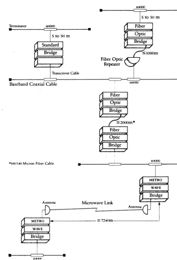
Figure 2.50
Extended Baseband L,\J'\"
Configuration and Distance Guidelines (Standard, Fiber Optic, and
METROWAVE Bridges)
Ethernet Configuration Guidelines
• Two METROWAVE Bridges connected by a microwave link count as two in the seven bridge limitation .
• Although it is packaged with an H4000 transceiver, the METROWAVE
Bridge can also be attached to standard Ethernet cable using a DELNI. to ThinWire cable using a DESTA, or to broadband cable using a DECOM.
The following figure illustrates the Extended Baseband LAN configuration and distance guidelines.
Terminator H4000
..
---~~~---. 5to50m Standard Bridge Fiber Optic Repeater H40005 to 50 m
Fiber Optic Bridge
• ~rn_sc_ei_ve_r_Ca_b_le __________ ~==~
__ C===J-____________ __
Baseband Coaxial Cable H4000 Fiber
Optic Bridge
~2000
m*Fiber Optic Bridge
lCron 1 er e
•
I
Fb Cabl H4000
METRO WAVE
Bridge
Antenna Microwave Link
Antenna-aJ
r
rD
II
METRO S7240m I
WAVE
Bridge
I
••
---~~r---
114(MMI••
[image:98.623.200.547.210.719.2](
Distributed System Cost Parameters
• Advantages
Lower communication costs
Modest startup costs (see below)
Low incremental expansion cost
Higher share of raw computing power available to the user
Better cost performance; faster reaction to new technological advances
Higher availability
• Disadvantages
High costs for extensive conversion
Distributed Systems Personnel Parameters
• Greater interest and motivation at local level.
• Identification with task of individual department's organization.
• More opporrtunities to communicate with and transfer into line management.
• Fewer skilled personnel required at each site.
~
I
(
I <4 Transceiver
1 Dble
Baseband Cable
DEC
MUX II
Ethernet Configuration Guidelines
G
Section 2.105 Ethernet Local Area Networks
(
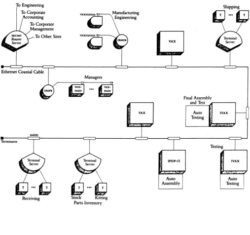
Factory ApplicationsFigure 2.9
Overview
The following figure illustrates a typical application of Ethernet in a factory. Such a configuration provides control of automatic assembly/test devices. Data entry stations provide timely information on the entire manufacturing process. Exchange of data between the manufacturing site and the rest of the corporation is handled through a router server.
Baseband Ethernet Factory Application
To Engineering To Corporate
Accounting To Corporate Management
To Other Sites
Ethernet Coaxial Cable
H4000 Terminator
Receiving
Managers
Stock Kitting Parts Inventory VAX VAX IPDP-tJ Auto Assembly
Section l.U Etbemet Local Area Networks
Shipping
Final Assembly
and Test r - - - ,
(
c-/
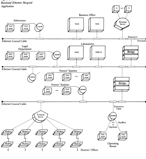
Figure 2.11
Baseband Ethernet Hospital Application
Admissions
Ethernet Coaxial Cable Legal Department
Ethernet Coaxial Cable
Ethernet Coaxial Cable
Overview
Business Office
G
VAXI
Laboratories
~---~ ~---,
VAX PDP-II
Nurses' Stations
Nurses' Stations
Doctors' Offices
Sedioa 2.14 Ethernet Local Area Networks
[image:102.617.44.556.94.648.2]...
~
SYSTEM
DXSK
o·
: E t h e r n e t
'I SAT 1
~O
SAT 2 LOCAL PAGE/SWAP DISK~
BOOT NODE 1 SAT 3Vlt.6
•
•
•
BOOT NODE 2 SAT 24ETHERNET-ONLY CONFIGURATION
-DUAL BOOT NODE
...
o
~
C I
~
VAX 1
lise
VAX
2
VAX
3
usc
I
~~I-9.a
d.i..sk
CI-only CONFIGURATION
~
VAX
I n
w
~
DECne~
CONFIGURATIONS
POINT-TO-POINT
ADAPTIVE ROUTING
MULTIPOINT
PACKET-SWITCHED (X.25/PSI)
ETHERNET
SERVERS AND GATEWAYS
CNOO
(,
r-'J ::z Q -\ \ \ \ I I I \ \ \ -0 0 ~CJ
:z
- I~
I - I~
0 I -0 0~
~:z
- I~
l)
~
(
c
~.
~.
c+
III
(
i
t
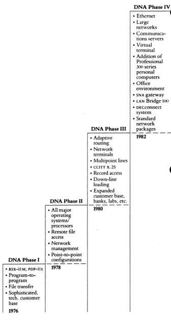
Figure 1.1
The Phases oJDNA and .4ssociatcd Capabilities
Digital Network Architecture Overview
DNA Phase III
• Adaptive routing • Network
terminals • Multipoint lines • CCITT X.2S
• Record access • Down-line
loading • Expanded
customer base,
DNA Phase II banks, labs, etc . • All major 1980
operating systems/ processors • Remote file
access • Network
management • Point-to-point
DNA Phase I configurations
-• RSX-IlM; PDP-Ils 1978
• Program-to-program • File transfer • Sophisticated,
tech. customer base
1976
1.3 DNA
DNA Phase IV
• Ethernet • Large
networks •
Communica-tions servers • Virtual
terminal • Addition of
Professional
3(Xl series
personal computers • Office
environment
• SNA gateway
• LAN Bridge toO
[image:108.618.251.588.66.696.2]i
I
I
~.
[image:109.612.49.572.121.686.2]C
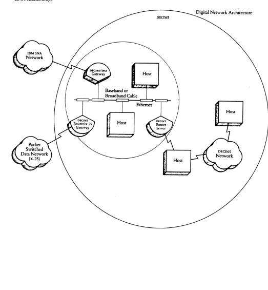
iFigure t.4
Ethernet,. DECnet, and DNA Relationships
Digital Network Architecture Overview
Baseband or Broadband Cable
Host
L9 DNA
. _ - - -
--.----~--.-DEenet
(
c··.·."
;./Application User
Presentation Applications
Other. DAP
Session Session Control
M N a
Transport End Communication n
e a
t g
Network Routing w e
0 m
(
r e
Data Link ODCMP X.2S Ethernet k n
t
Physical Physical Physical Physical
OSI
DNA
A P P L I C A T I
o
N c o..
..
u N r C A T Ia
N ~\ "' ~ ~
DNA MODULES RESIDENT IN FI DECnet NODE
MANAGE NETl.IORK
I I
TASK -TO- TASKI
FILE ACCESSI
I
I
USER LAYER
NCP UTILITYI I
USER PROGRAM 1I
USER PROGRAM 2I
NETlJORK
NETWORK MANAGEMENT7
MANAGEMENT
ROUTINESNETlJORK
~
/ 'r
REMOTE FILE ACCESS ROUTINESI
APPLICATION
; /
SESSION
"- /I
CONTROL
SE SSION CONTROL MODULEEND
I
NSP MODULE
J
COMMUNICATION
IROUTING
I
I ROUTING MODULEr
1
DATA LINK
I
[I)(}f ImLEI
X'25 M(]JJLEI
I
EnERr£T IUJlLEI
-
-
...""'"'-PHYSICAL
LltEA 's LItE B 's LIrE C's LItE 0 's LINE E 'sC()ff~ER CONTIU..LER CONTIU..LER CONTRO..LER CONTROLLER
COMMUNICATION
I
/
/
J
/
FACILITIES
A
E. G. A TElffHl£ LItE E. G. A UrAL L1J( E.G.
ANlJTIfR
LOCAL LUi
EllfR£T (illES
PR 03
OSI
and
DNA
c
1.3.2 The Layers of DNA
OSI Application DNA Application
Application Presentation
Naming DNA
Service Session Control Session Transport
Network Data Link
Physical
. Figure 1.3: The Layers of DNA
(n-l)-layer n-Iayer (n+ 1 )-layer ( n+ 1 )-layer PCI PCI PCI User Data
l
n-layer User Data nPDUFigure 1.2: Nesting of Protocol Control Information
[image:112.612.76.488.551.613.2]-(
X.25
• Specifies the communication interface between DTEs and DCEs on the PPSN.
• Defines three functional levels (similar to RS232-C and to the lower levels of DNA).
Level 1 (Physical Interface) - Defines the physical and electrial characteristics of the connection between the DTE and the DCE.
Level 2 (Frame Level) - Defines the rules for transmitting data between the DTE and DCE.
Level 3 (Packet Level) - Defines the rules for transmitting and controlling the packet.
• CCITT's X.3, X.28, and X.29 recommendations define an interactive terminal interface for devices such as
ansynchronous hardwired terminals that want to communiclte over a PPSN, but cannot be programmed according to the X.25 format.
(
(-DTE COMPUTER OR
INTELLIGENT TERMINAL
I
X.25
I
I
I
I
L
X.25, X.28, X.3, X.29, X.75 STANDARDS (RECOMMENDATIONS)
DeE
DCE
I
I
PADX.3
SWITCHING
EXCHANGES ---1_'- X.29
I
X.25I
I
- - - -
-~
4-54
DTE
DUMB TERMINALS
(
(
(
Digital's Interconnect Strategy with IBM
To create an environment which accommodates t.he
transparent,
bi-directional flow of information
between Digital and IBM data
processing systems.
(
Complementary Computing
• Gateway concept
Provides access between the Digital and IBM
processing
environments
Allows either vendor's
netwo.rk
to expand based on the
customer's needs
(
• User Transparency
Insulates the users and their applications from changes
in the network
Allows for
~nhancementsand changes in either network
• Provide a
Network-to-Network
solution between the two
vendors
- Viable in any arbitrary topology supported by DECnet
Bridging the Difference
(
..
.(:
Digital's
SNA
Product Set Architecture
(
An example of the DECnet/SNA Gateway
OtGITAl
SYSTEM
OECnetlSNA
GATEWAY
OfGITAl
SYSTEM
(
(
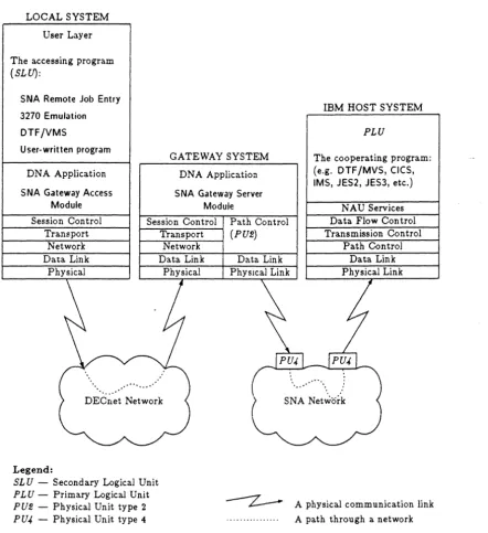
LOCAL SYSTEM User Layer The accessing program
(SLU):
SNA Remote Job Entry 3270 Emulation DTF/VMS
User-written program DNA Application SNA Gateway Access
Module
GATEWAY SYSTEM DNA Application SNA Gateway Server
Module
IBM HOST SYSTEM
PLU
The cooperating program: (e.g. DTF/MVS, CICS, IMS, JES2, JES3, etc.)
NAU Services Session Control
Transport
Session Control Transport
Path Control
(pm)
Data Flow Control Transmission Control Network
Data Link Physical
Legend:
SL U - Secondary Logical Unit
PLU - Primary Logical Unit
pm - Physical Unit type 2
PU4 - Physical Unit type 4
Network
Data Link Data Link PhYSICal Link
[image:119.618.82.525.70.553.2].... ...
Path Control Data Link Physical Link
SNA Network
--z.--
A physical communication link ... A path through a networkFigure 11.1: SNA Gateway Access Operation
Routines Involved in using the Gateway
-.
-(
D
R
D
P
H
J
T
D
r
L
A
L
C
E
X
E
U
F
E
F
P
U
6
S
I
2
2
N
S
A
N
N
T
C
Internal
A
P
R
A
p
F
A·
Basic Applications InteJface
C
L
E
DECnet
VMS
.~--.--.-~
(
An Example
or
VMS/SNA
Prop-ammiDI Interfaces
• DECnet/SNA VMS Application Programming
Interface (API)
• DECnet/SNA
VMS
3210
Data
Stream
Proll'ammiDllnterface
(3210 OS)
(
DISK