Sydex
AnaDisk
The Compleat Diskette Utility
Sydex
153 North MurphyAve.
AnaDisk
The Compleat Diskette Utility
Version 2.01, November, 1989 Copyright 1989, Sydex. All Rights Reserved.
NOTICE
THIS IS NOT FREE SOFTWARE! If you paid a "public domain" vendor for this program, you paid for the service of copying the program, and not for the program itself. Rest assured that nothing ever gets to the originators of this product from such a sale. You may evaluate this product, but if you make use of it, you must register your copy.
We offer several inducements to you for registering. First of all, you receive the most up-to-date copy of the program that we have -- and we do upup-to-date the product on a regular basis. you also receive support for AnaDisk -- which can be quite valuable at times. You also receive complete printed documentation for the product. A "do-it-yourself' update service is offered to registered users through our own BBS. And finally, we include an evaluation package of some of our other software products. Make no mistake, however--this is a fully functional version of AnaDisk and not "crippled" in any way. As a final inducement to you--the registered package does not contain the advertising copy ...
REGISTRATION INFORMATION
The non-commercial single-user registration fee for AnaDisk is $25.00 US. The commercial and multisystem site fee for AnaDisk is $150.00. Users outside of Canada and the United States should include an additional $5.00 for international airmail. We can accept payment only in U.S. funds.
Send a check or company P.O. for the appropriate amount to:
Sydex
153 North Murpby Ave. Sunnyvale, CA 94086
We can also accept VISA or Master Charge; contact us for details. On corporate orders, our terms are normally net 30. Please indicate what product you are ordering and if you have a re-quirement for 3.5" media. We normally ship 5.25" 360K diskettes, but will furnish 3.5" 720K media upon request.
DISTRIBUTION NOTICE
This is "user-supported" software. You are hereby granted a license by Sydex to distribute this evaluation copy of AnaDisk and its documentation, subject to the following conditions:
1. AnaDisk may be distributed freely without charge in evaluation form only.
2. AnaDisk may not be sold, licensed, or a fee charged for its use. If a fee is charged in connection with AnaDisk,. it must cover the cost of copying or dissemination only .. Such charges must be clearly identified as such by the originating party. Under no
cir-cumstances may the purchaser be given the impression that he is buying AnaDisk it-self.
3. AnaDisk must be presented as a complete unit, including this documentation. Neither AnaDisk nor its documentation may be amended or altered in any way.
4. By granting you the right to distribute the evaluation form of AnaDisk, you do not be-come the owner of AnaDisk in any form.
Any other use, distribution or representation of AnaDisk is expressly forbidden without the written consent of Sydex.
Overview
Installing AnaDisk Running AnaDisk Scan Operation
Edit Sectors Operation Examine Files
Search
Copy Diskette Repair
FAT Editor
Custom Format Design Dump Operation Looking Forward
Table of Contents
A Short Course on Diskettes Getting Down to Bits
Copy Protection, or, Ways to Skin A Cat High-Density Variations
DOS Diskettes - FATS, Clusters and Directories
Appendix 1- Disk Track Formats
Appendix 2 - DOS Directory Entry Format Appendix 3 - Boot Sector for DOS Diskettes
The Sydex Product Line
1
1
4
6
10 14 17
22
23
25
26
28
29
31
33 37 38 39
42
44 45
Overview
AnaDisk is a utility for examining, editing and analyzing diskettes. It performs the following functions:
*
*
*
*
*
*
*
*
Analyze diskettes for content and consistency. The density-and format. of dis-kettes are automatically determined; any format changes or media errors are noted. In the case of DOS diskettes, checks are made to ensure that· a dis-kette complies with generally accepted DOS implementation practice.
Search diskettes for text. Both case-sensitive and case-insensitive searches may be performed, as well as search keys with 'Wild card" or "don't care" posi-tions. Both the active data areas, as well as the inactive or erased data areas may be searched.
Examine and print data on a physical sector, as well as on a file basis. Either ASCII or hexadecimal displays may be used.
Copy a diskette without regard to format or type. Modify data on a diskette.
Repair DOS diskettes containmg data errors.
Format a diskette according to custom specifications. Copy an area of a diskette to a DOS file.
AnaDisk features a menu-driven ''windowed'' presentation. Extensive context-sensitive on-line help is available.
AnaDisk requires an
mM
PC or PS/2 compatible computer for operation. Certain com-puters, such as the Tandy 1000, 2000 or the ffiM PC Jr., are not sufficiently compatible to support AnaDisk.At least 512K of memory and a hard disk are recommended for AnaDisk operation, al-though some function may be obtained with as little as 384K on a diskette-only system.
Installing AnaDisk
The software for AnaDisk is contained in two programs. The first, the installation program,-. ; called ADINSTAL, is used to determine the diskette configuration of the computer being used. This installation program modifies the second part, the file ANADISK.EXE, with the diskette configuration information.
AnaDisk IHSTALLATIOH PROGRAM Uer. 2.91
Copyright 19B9~ Sydex. All Rights Reserued.
This prograN installs AnaDisk.
Installation is a one-tiNe task: you should not need to re-run this prograN unless you haue changed your equipNent configuration.
Installation Nay he perforNed with a single diskette~ or any coNhination
of diskettes and hard disks. The Nost CONNon installation is froN a diskette to a hard disk. During this installation~ you will he asked
to prouide a copy of the AnaDisk files. If you don~t haue these
files~ press ESCape to exit now. This installation procedure selects
diskette driue types and processor type. In addition~ the installed
AnaDisk is copied to a destination driue of your choice.
[image:6.621.52.553.55.396.2]If you do not wish to install AnaDisk at this tiNe~ press ESCape. Press any other key to continue ...
Figure 1: ADINSTAL Opening Screen
AnaDisk must be installed prior to use. After installation, AnaDisk need not be re-installed unless the configuration of the computer being used is changed. It is possible to re-install an already installed copy of AnaDisk.
To install AnaDisk, first load DOS. Insert the AnaDisk distribution diskette into diskette drive A:, then enter the following command:
A:ADINSTAL and press the ENTER key.
The display in Figure 1 will appear. Press the ENTER key to continue with the installation process.
Prompts will appear for the source and destination disk drives. AnaDisk may be re-installed over itself, if need be. Otherwise, the source copy of AnaDisk is not modified by the installa-tion software.
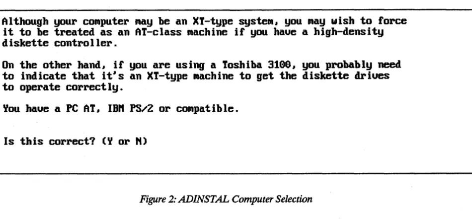
Although your conputer nay be an XT-type systen, you nay wish to force , it to be treated as an AT-class nachine if you haue a high-density
diskette controller.
On the other hand, if you are using a Toshiba 3199, you probably need to indicate that it's an XT-type nachine to get the diskette driues to operate correctly.
You haue a PC AT, IBH PS/2 or conpatible.
[image:7.617.76.551.72.294.2] [image:7.617.67.557.344.600.2]Is this correct? (Y or N)
Figure 2: ADINSTAL Computer Selection
If permitted, ADINSTAL will attempt to determine the diskette configuration of the com-puter. In any case, a display similar to the following screen (Figure 3) is shown:
DISKETTE CONFIGURATION
The following diskettes are present on your conputer:
NO. DRIVE UNIT ADAPTER DRIVE TYPE STEP RATE
1. A: 9 PRIHARY
2. B: 1 PRIHARY
3. (NONE DEFINED) 4. (NONE DEFINED) 5. (NONE DEFINED) 6. (NONE DEFINED) 7. (NONE DEFINED) 8. (NONE DEFINED)
1.2M 5.25"
1.44H 3.5"
Are there any changes? (Y or N)
Figure 3: Diskette Configuration Display
6 nsec. 6 nsec.
Information contained on this display may be changed until the data reflects the actual con-figuration of the host computer. DRIVE is used by AnaDisk to refer to a diskette drive. While it is advisable that the drive letter be the same as that used by DOS to refer to that drive, any letter can be used. UNIT refers to the physical unit number of a drive. Some dis-kette adapters are able to access only two drives, physical units 0 and 1. Other adapters, particularly those of the XT variety, can access up to four drives, physical units 0, 1, 2 and 3.
If a second diskette adapter has been added to the host computer, it will be necessary to . configure units attached to that adapter as Secondary. Note that, on secondary adapters, the physical unit numbering starts over again with unit O.
The drive step rate refers to how quickly the positioning mechanism in a drive is able to move the read/write heads from cylinder to cylinder. In almost all instances of 5.25" drives, the default of 6 milliseconds will be satisfactory. This value sometimes needs to changed for some of the older 8" diskette drives.
AnaDisk does not explicitly support dual-speed 5.25" drives. A dual-speed drive is one-that rotates· the media at 300 RPM for low-density recording and 360 RPM for high-density recording. If it is desired to use a dual-speed drive, it must be declared as two separate . drives, a high-density drive, and a low-density drive, using two different drive letters.
After the diskette drives have been configured for AnaDisk, the installed program file is written to the specified destination path and drive, and AnaDisk is ready for use.
Running AnaDisk
To start AnaDisk, simply enter the following at the DOS prompt: ANADISK
and press the ENTER key. AnaDisk will normally adjust its video display routines to make use of the display adapter in use. However, if the display adapter is of a color type and the display monitor itself is monochrome, it will be necessary to start AnaDisk with the following· command to get a readable display:
ANADISK M
AnaDisk has many displays and functions, but there are certain keys which always have the same effect during AnaDisk operation:
Fl is the Help key. It may be pressed any time additional information is re-quired. The help displays in AnaDisk can be characterized as being Context-Sensitive. That is, only information relevant to the current operation is presented. For example, if AnaDisk were prompting for a file name, Fl would produce a display that presented information about the application of the file being requested.
When an abnormal condition has been detected in AnaDisk, a small window describing the condition will appear. This window is referred to as the "Alert Box":
r.===========t
.I...
to noue=========n Driue A: is not ready.Please correct and press any key to continue.
The Alert Box may be moved around the screen by means of the cursor keys. Up- and down-cursor move the Alert Box up or down one character row, respectively. Right- and left-cursor have a similar effect. The Home key moves the Alert Box to the upper left cor-ner of the display; End moves it to the lower left. Pg Up moves the Alert Box to the upper right corner of the display and PgDn moves it to the lower right.
, After AnaDisk is loaded by DOS, the following display (Figure 4) appears:
ESC to Exit AnaDisk 2.01 Fl for Help
::le:ct -ESCa]~et,o quit. Fl for help
nAItt nEttU
Select function with •• cursor keys. EttTER (~-1) confirMS your choice and goes to next Menu. Fl gets help. ESCape exits to DOS.
[image:9.615.70.553.325.636.2]SCAtt SECTOR FILE SEARCH COpy REPAIR FAT FORnAT Dunp
Figure 4: AnaDisk Opening Display
If the ESCape key is pressed, AnaDisk exits to DOS. Otherwise, the cursor right- and left-arrow keys are used to position to highlight, and thereby select, the desired function. After a function has been selected, pressing the ENTER key will cause a menu specific to the par.; ·
ticular function to be displayed. .
The functions performed by AnaDisk are as follows:
The Scan function reads an entire diskette and points out any problems or inconsis-tencies. A quick look is taken at all of the files on the diskette and checks are made to ensure that file contents are consistent with the file type. A ''log'' of the activity can be printed, if desired.
Sectors provides a diskette editing function, operating on a sector-by-sector basis. Diskette data can be printed, displayed or changed.
Files provides a facility to examine file data on the basis of file name, rather. than physical diskette sector addresses. It is possible to "walk" the directory tree and print or display file data.
Search provides a facility to search for data on a diskette. A number of search key values can be specified and these may contain ''wild-card'' or "don't care" values. The results of the search can be displayed or printed.
Copy provides a disk-to-disk copying function. A "true" copy of ,an entire diskette is produced within the limits of the PC diskette adapter hardware. It is not necessary to pre-format the target diskette, but it is advisable to write-protect the source diskette.
Repair scans a DOS diskette for data errors and attempts to mitigate their effect by "moving" the contents of erroneous sectors to other areas of the diskette. FAT provides a DOS File Allocation Table editor.
Format supplies a custom diskette formatting capability. ,This is a feature intended, for advanced users.
Dump copies specified areas of a diskette to a DOS file. The diskette being copied need not be a DOS diskette.
As is the case throughout AnaDisk, help may be obtained by pressing Fl.
Scan Operation
ESC to Exit AnaDisk 2.91 Fl for Help
I
I!= ===-===-===-============-======-===-===-===-====11
1
111
Select - ESCape to qllit. Fl 101' helpI
Scan DISKETTE
Select choices with ++ cursor keys. "oue between lines with f~
keys. EHTER (~-1) begins execution. F1 gets help, ESCape goes back to the opening ~enu.
Diskette Unit A: B:
Printer output ~ YES
[image:11.612.66.549.77.367.2]Pause after ano~alies ~ YES
Figure 5: Scan Menu
The Scan function reads an entire diskette and attemptsto discover data errors or inconsis-tencies. AnaDisk first determines the layout of cylinders, tracks and sectors, then attempts. to classify the diskette accordirig to operating system type. If the diskette appears to have a DOS format, a validity check is made of the File Allocation Table (FAT). Finally, every sec-tor of the diskette is read, and errors and format changes noted.
If Pause after anomalies on the Scan menu is selected, some information is presented by opening an additional window which overlays the display and temporarily suspends AnaDisk operation until acknowledged from the keyboard. If Pause after anomalies is not selected, important information is written in the ANALYSIS window, but operation of AnaDisk is not suspended.
If Printer output is selected, a running log of analysis information is printed on the default printer (the DOS PRN: device).
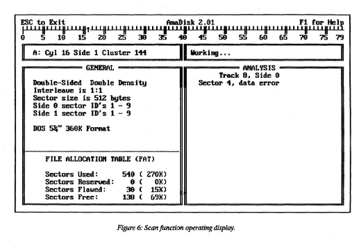
A normal Scan function operating display is shown in Figure 6. The "thermometer bar" across the top of the screen indicates where AnaDisk is positioned on the diskette. The small arrow on the display points down if the first side of a diskette is being accessed, or up for the second side. In addition, position is also shown in the small window in the upper-left part of the display. A progress message is displayed in the small window in the upper-right part of the display.
-I~~
,1
8,
~~!u'
, ,
'lit' , 'II' ' , 'II' ' , 'II' ' ,
'II'~'~U~~' ~ il~t, 'II' , , 'II' , , 'II' , , 'II"
,~u' ~~~ II~!V
. 8 5 18 15 29 25 39 35 49 45 58 55 68 65 78 75 79
I
A: Cyl 16 Side 1 Cluster 111II
Working ••.n================== GEtlEHAL -=================n rr=============== MALYS IS
=========---=a
Double-Sided Double Density Interleaue is 1:1
Sector size is 512 bytes Side 8 sector ID·s 1 - 9 Side 1 sector ID·s 1 - 9 DOS 5%" 368K ForMat
FILE ALLOCATIOn TABLE (FAT) Sectors Used:
Sectors Reserued: Sectors Flawed: Sectors Free:
549 ( 279K)
9 ( 9K)
38 ( 15K) 138 ( 69K)
[image:12.617.52.559.59.416.2]Track 8. Side 8 Sector 4. data error
Figure 6: Scan function operating display.
The window labeled GENERAL contains information about the static or unchanging aspects of the diskette under examination, such as number of sectors per track and File Allocation. Table information. The window labeled ANALYSIS describes events of a dynamic nature, such as read errors and anomalies in diskette structure. This window uses a scrolling dis-play; that is, the oldest information is replaced by the newest.
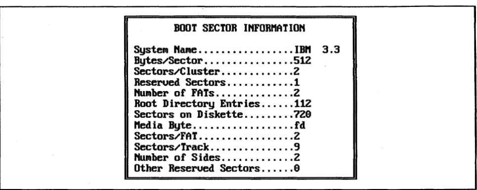
For DOS diskettes with readable file allocation information, the lower part of the GENERAL window presents the data contained in the File Allocation Table (FAT) on the diskette.
BOOT SECTOR INFORHATION
[image:13.615.69.552.71.264.2]SysteN NaNe ..•...•... IBH 3.3 Bytes/Sector ...•....•... 512 Sectors/Cluster ...•.... Z Reserued Sectors ... 1 NUNber of FATs ...•... Z Root Directory Entries ... 112 Sectors on Diskette ... 7Z0 Hed ia Byte ....••.•... fd Sectors/FAT ..•... Z Sectors/Track ...• 9 HuNber of Sides ... Z Other Reserued Sectors ... 0
Figure 7: Scan [unction Boot Sector display.
If the number of sides declared by the DOS Boot Sector does not match that actually detected by AnaDisk, one of the following messages appears:
r.============,t ,a.-u- to Houe'=============n This is a double-sided DOS forNat. but only one side
r.============t ,a... to Houe'===========iI This is a single-sided DOS forNat. but both sides has data. Press any key
to reSUNe ... haue data. Do you want to check both sides (Y or N)7
The Scan function can detect media errors. A few of the more common error messages dis-played in the ANALYSIS window are:
Data Error
Meaning: Information has been read from the diskette, but internal checks made by the controller indicate that the data transferred is suspect.
IDbut no Data Found
Meaning: The marker identifying the beginning of a sector is present, but not the marker that signifies that data follows. No data is transferred by the diskette controller.
Sector Hissing Gap in Addresses
Meaning: In DOS diskettes,. sectors are numbered consecutively. This message indicates that one or more sectors could not be found in the normal numbering sequence. This mes-sage can also be indicative of some copy-protection schemes.
"0
Data on TrackMeaning: The diskette track may be blank or be written in some other recording mode, such as single-density or those modes used by Apple or Commodore. It is not possible. to read this track with the standard PC-style diskette adapter.
Edit Sectors Operation
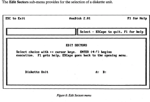
When the Edit Sectors operation is selected from the Main Menu, the display shown in Figure 8 appears.
The Edit Sectors function provides a facility to inspect, change and print diskette data on a sector-by-sector basis, as contrasted with Examine Files, which implements inspection of data within a specified DOS file.
The Edit Sectors sub-menu provides for the selection of a diskette unit.
ESC to Exit AnaDisk Z.91 F1 lor Help
I
I!::=============:=!III
Select - ESCape to quit. F1rOl'
helpI
EDIT SECTORS
Select choice with ++ cursor keys. E"TER (~-1) begins
execution. F1 gets help, ESCape goes back to the opening .enu.
[image:14.621.63.557.308.643.2]Diskette Unit A: B:
Figure 8: Edit Sectors menu
The right- and left-cursor keys are used to select the track; the up- and down-cursor keys are used to select the head or side containing the sector. The "thermometer" line shows this position change correspondingly. When the ENTER key is pressed, the track is read for analysis and a track map is displayed as shown in Figure 9.
~~
, to
,~~!
U' , , ,
II' , , , II' ' , , II' , , 'II' ' , ,
II~m U~~ ,~ il~t,
, II' ' , , II' ' , , II' ' , , II'
I I~H
I~~~
H
~
!r
o
5 10 15 20 Z5 39 35 40 45 59 55 60 65 70 75 79I
A: Cy I 1 S idea
Cluster 5 IlI=s==e==le==c==t====sec=to=r=============================-====II n======================--==-============ TRACK "AP --====-=====================-====== .... - ....Select sector fl, EHTER starts edit, Change track . . , Exit ESC
CYL HEAD SECT SIZE FLAGS
1 9 1 512
1 9 2 512
1 0 3 512
1 1
1
1
1
1
9 9 9 9 9 9
[image:15.617.66.551.147.458.2]4 512 5 512 6 512 7 512 B 512 9 512
Figure 9: Edit Sectors track map
The desired sector is selected from the displayed track map by use of the up- and down-cursor keys. When the sector to be edited is highlighted, the ENTER key is pressed to dis-play the data for that sector. If either the right- or left-cursor key is pressed, the next or pre-vious track is analyzed, and the track map for that track displayed. If the ESCape key is
pressed, AnaDisk returns to the track selection display.
Sectors having errors are marked in the track map with an E in the FLAGS column; those having a Deleted Data Address Mark are marked with the letter M.
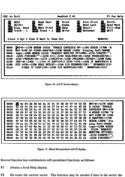
When the desired sector has been selected, the editing display appears as shown in Figure 10. Initially, sector data is displayed in an ASCII representation, with undisplayable control characters shown as dots. The F8 key may be used to toggle between this ASCII display and a mixed hexadecimal-ASCII display, as illustrated in Figure 11. The current position within the sector data is indicated by a highlighted reverse video block, and may be moved by use of any of the cursor keys. Data on the display may be changed by simply entering new data at the current position. However, data
is
not written to the d#kette until Alt-F2is
pressed. If data is changed, the notation ALTERED appears in the menu window.ESC to Exit AnaDisk z.al Fl for Help
•
HELP lRead Sect • Print
I . Shift.. I HOT I ; Alpha I Diag. Read I What Fi Ie? I · Saue
I · Track - 1 I 0 Track + 1 I * Write
~
. Disk Print
I
Shift·I · Read Last I 0 Read
next
I Recall I . Fi II-)EOO I * Refor.at I QU I TClust 3 Cyl 1 Side a Sect 9. Size 512
aaaa aa4a 808a a0c0 0100 0140 0180 01c0 0000 0010 00Z0 0030 0040 0050 0060 0070 0080 0090 00a0 00b0 80c0
jDtT=0 •• 1170 GOSUB 14310 • TOGGLE CAPSLOCK 0" •• 1180 GOSUB 11780 ·W HAT KI"D OF UIDEO ADAPTER •• 1199 GOSUB 11850 ·display Soft-SHARE
logo •• 1200 GOSUB 12120 • REQUEST RU"T InE OPT IO"S •• 121a STAR TS="" • .lZZ0 FI"ISH$='''' •• lZ30 S=1 •• 1249 ROWLI"ES=10 •• 1Z50 PAGESIZE=50 •• lZ60 FREELnT=10 •• 1270 LI"ECHT=9 •• 1Z80 PRULnUn=-3Z768! •• lZ98 CURL
I"E!=0 •• 1300 • •• 1310 IF RUHTYPE<3 GOTO 1470 •• 13Z0 IF RU"TYPE>4 G OTO 1470 •• 1330 READ RESC"T •• 1349 DIn RESWRD$(158) • RESWRD$(153)
[image:16.620.67.553.27.713.2]FIXED IF conPILED •• 1359 DIn WORDFLAG(158) • WORDFLAG(153)
Figure 10: ASCII Sector display
~ 4e 54 3d 30 0d 0a 31 31 37 3a Z0 47 4f 53 55 42 Z0 31 34 33 31 30 20 Z7 54 4f 47 47 4c 45 Z0 43 41 50 53 4c 4f 43 4b Z0 4f 4e 0d 0a 31 31 38 30 Z0 47 4f 53 55 4Z Z0 31 31 37 39 30 Z0 Z7 57 48 41 54 Z0 4b 49 4e 44 Z0 4f 46 Z0 56 49 44 45 4f Z0 41 44 41 50 54 45 5Z 0d 9a 31 31 39 30 Z0 47 4f 53 55 42 Z0 31 31 38 35 3a Z0 27 64 69 73 70 6c 61 79 20 53 6f 66 74 2d 53 48 41 52 45 Z9 6c 6f 67 6f 9d 0a 31 3Z 30 39 2a 47 4f 53 55 4Z 20 31 3Z 31 3Z 30 Z0 Z7 5Z 45 51 55 45 53 54 Z0 5Z 55 4e 54 49 4d 45 Z0 4f 50 54 49 4f 4e 53 0d 0a 31 3Z 31 3a Z0 53 54 41 5Z 54 Z4 3d ZZ ZZ 0d 0a 31 32 3Z 3a Z0 46 49 4e 49 53 48 Z4 3d Z2 ZZ
Figure 11: Mixed Hexadecimal-ASCII display.
R"T=0 .... 1170 GOSU B 14310 ·TOGGLE CAPSLOCK OH .... 118
o
GOSUB 11780 ·W HAT KIHD OF UIDEo
ADAPTER .... 1190 GOSUB 11850 ·dis play Soft-SHARElogo .... 1200 GOSUB 12120 • REQUEST RUHTIn! OPTIOHS .. .. 1210 START$=,m .. .. 1220 FIHISH$="u
Several function key combinations will specialized functions, as follows: Fl obtains a brief Help display.
F3 Prints the current sector on the DOS printer (PRN:). A mixed hexadecimal-ASCII format is used.
F4 Writes a mixed hexadecimal-ASCII representation of the sector data to a standard DOS file. If the DOS file exists prior to the F4 operation, the data is appended to the end of the file. Otherwise, a new file is created.
FS Shifts the data from the current (highlighted) position to the end of the sector one bit left. Bits shifted out of the high-order positions of the current byte are lost; low order posi-tions at the end of the current sector are filled with zero.
F6 Shifts the data from the current (highlighted) position to the end of the sector one bit right. Bits shifted out of the low-order positions of the last byte in the sector are lost; high-order bit positions at the current byte are filled with zero. The shift-right and -left functions are useful in reconstructing information in a sector which has become garbled because of a data read error.
F7 Performs the one's complement Boolean operation on sector data from the current (highlighted) position to the end of the sector.
F8 Toggles the display mode from ASCII to mixed ASCII-hexadecimal.
F9 Reads the sector immediately preceding the current one. If the current sector is the first on the track, the last sector on the previous track is read.
FlO Reads the sector immediately following the current one. If the current sector is the· last on the track, the first sector on the next track is read.
Shift-F2 Performs a "diagnostic read" of the current track. A diagnostic read involves read-ing the data field of the first sector and continues with all fields unti116,384 bytes have been read. ID fields, gap bytes and CRCs are read indiscriminately; no attempt to re-synchronize the data discrimination logic is made after the first sector has been read. This function allows viewing of raw data and may be used to determine the value of a data field whose address ID field has been corrupted, or data contained within inter-sector gaps. See
the Diskette Tutorial section for more information.
Shift-F3 Identifies the file of which the sector is a part. Note that is function is available only for DOS diskettes.
Shift-F4 Saves the contents of the sector in an internal buffer. ~Each time Shift-F4 is
depressed, the previous contents of the save buffer are lost.
Shift-FS Recalls the contents of the save buffer to the current display. Note that the con-tents of the buffer are not written to the diskette.
Shift·F6 Fills the sector from the current position to the end of the sector with the value at the current position.
Shift·F9 Analyzes the preceding track and displays the track map forit. If the current track is the first on the diskette, it is re-read ..
Shift·FIO Analyzes the following track and displays the track map for it. A1t·F2 Writes the contents of the editing display back to the diskette.
A1t·F3 First reads all sectors~ on the current track, then re-formats the current track with a fresh format pattern, then re~writes the sectors back to the track. A display requesting con-firmation appears before the track is reformatted.
ESCape Returns to the track map for this track.
In addition to this information, the menu window also shows the current sector, the position within the sector in both decimal and hexadecimal and the following flags, if applicable:
ERR The sector could not be read without error. Before an attempt is made to read a sector, the data is set to all zero. If the error is one that results in no data being transferred, the display will show all zero.
CTL MK A Deleted Data ID Address Mark was detected on the current sector. DOS makes no use of this feature and never writes this flag, but AnaDisk does detect its presence and reports it.
Examine Files
The Examine Files function provides for examination of data contained in DOS files. After the Examine Files function has been selected from the Main Menu, the diskette unit to be examined is selected from a subsidiary menu similar to that used for Edit Sectors.
In the window displaying file names, the meanings of the column labels are as follows: NAME is the name of the file.
ATIRIB show flags for the file attributes. These are as follows:
A is the "archive" flag. This flag is used by back-up utilities and is set when-ever the file is created or modified. Most back-up utilities clear this flag once the file has been backed up.
D is the "directory" flag. When this flag is present, the name shown is the name of a directory, rather than a file.
V is the 'volume label" flag. When this flag is present, the name shown is the name of the volume label for this diskette. This name can be changed by means of the DOS LABEL utility.
H is the "hidden" flag. When this flag is present, the file name will not be shown in a DOS directory listing.
R is the "read only" flag. When this flag is set, DOS will not permit the file to be written to. This flag is modified by means of the DOS ATTRIB command.
S is the "system" flag. This flag is normally only associated with DOS files loaded at system "boot" time. Files flagged with this attribute are also implicitly read-only and hidden (R and H attributes).
To examine the files in a particular subdirectory, highlight the subdirectory name and press ENTER. To go back to the parent directory of a subdirectory, position to the •• entry and press ENTER.
Several functions are available on the Examine Files menu: FI obtains a brief Help display.
F2 causes the Edit Sectors display to be activated, using the first sector of the current (highlighted) file. All functions on the Edit Sectors menu operate normally, with the following exceptions:
F9 moves one sector back within the file.
FlO moves one sector forward within the file.
Shift-F9 and Shift·FIO do nothing.
ESC to Exit
I
HelpI • Show De leted
Edit FAT
AnaDisk 2.91
U
xa.ine SectorI Print ASCI I
I • Select Directory
Fl for Help
I
DiSPlay Fi IeI • Print Hex I Exit
Attributes: Archiue Directory Uolu.e label Hidden Read only Syste. Directory: ,
HAI1E ATTRIB TII1E DATE LEftGTH CLUS
I1KCHARS.C A 14:17:21 11/16/89 1195 2
TEXT2DAT .C A 14:17:21 11/16/89 993 4
II1GCPY.C A 14:17:21 11/16/89 6958 5
SAUECI10S.C A 14:17:22 11/16/89 4443 11
PUTCI10S.C A 14:17:22 11/16/89 5919 16
CGErt2ASI1.C A 14:17:24 11/16/89 1127 42
CGErt2HP.C A 14:17:24 11/16/89 8594 44
[image:20.620.44.555.51.693.2]PRUrtE.C A 14:17:24 11/16/89 4993 53
Figure 12: Examine Files display.
ESCape returns to the Examine Files menu, not to the track map.
In addition, the relative byte offset within the file is displayed, in addition to the cylinder, side and sector.
F3 displays the currently highlighted file as ASCII text. The up, cursor-down, PgUp, PgDn, Home and End keys may.be used to navigate within a file. ' Data past the end-of-file point is displayed following the notation:
»>
ErtD-OF-FILE«<
F4 toggles the file directory display between Active and Deleted or erased files. A deleted file always has a "sigma" as the first character of the name. Figure 13 shows a deleted files display.
FS causes the currently highlighted file to be printed as ASCII text. Data past the end-of-file point is also printed, with the end-of-file shown as in the F3 func-tion, above.
ENTER changes the display to the highlighted directory. To return to the parent of the current directory, highlight the •• entry and press ENTER.
ESC to Exit
I
HelpI Print ASCI I
AnaDisk 2.91
I
ExaMine Sector ~splay FileI • Print Hex ~ Select Dir.
Fl for Help !lLShow Actiue
• Exit Attributes: Archiue Directory
Hidden Read only
UolUllle label SysteM
Directory: ,
HAME ATTRIB TIME DATE LEHGTH CWS
[image:21.617.66.550.96.360.2]Dntl·11a1;ll:t~ A 15:1&:91 95.11&.189 71313 &8 O"RCHECH.EXE A 11:55:20 9&.129.189 5084 392 O"HSTALL.EXE A 19:3&:95 99.197.189 9 0
Figure 13: Deleted files display.
It is possible to display and print data belonging to deleted files, if the file has not already been oveIWritten. IT an attempt is made to display or print an oveIWritten file, the following message will be displayed:
1F='===t .j.-+ .. to Moue=====iI
This deleted file has been ouerwritten. Press ESCape to quit displaYJ Any other key to proceed ...
IT the ESCape key is pressed, AnaDisk returns to the file directory display. If, however, any
other key is pressed, AnaDisk displays information as if the file were not overwritten. To gather data for display, AnaDisk searches (forward) for the next unallocated area and
dis-plays it. Depending on the method by which the file was created, however, this may not ac-tually reflect data contained in the file beyond the first allocation unit or cluster.
Search
AnaDisk's Search function will examine a diskette for a match on anyone of a series of search key values, referred to simply as keys. The search can extend over the entire dis-kette, the active file area, or just the deleted (inactive) area. Up to five 65-character keys may be specified; AnaDisk will search for all keys simultaneously and report a match on any key.
Keys may contain what are known as "don't care" or "wild card" values, which will match any
character. To obtain the most efficient performance, a key should not begin with a "don't care" value. In addition, the search may be instructed to ignore the case of alphabetic data; e.g., the letter A will match both a and A.
The Search menu is shown in Figure 14. The Source for search value selection offers two al-ternatives:
KEYBOARD specifies key entry from the keyboard. After all key values are entered, they may be saved to a file for later recall.
OLD VALUES specifies that the keys entered for the preceding search should be used. This option is invalid for the first search of a AnaDisk session.
Search alpha case-sensitive specifies whether the search should consider the case of al-phabetic characters. If NO is selected, the search considers both upper- and lower-case al-phabetic characters to be equivalent. Thus, DOG will match both DOG and dog if the search is not case-sensitive.
ESC to Exit AnaDisk
2.a
F1 for Helple:I
========::;::=:==============u1I
Select - ESCape to quit. F1 for helpI
SEARCH DISK FOR DATA
Select choices with ~ cursor keys. Moue between lines with fl keys. EHTER ( .. ~) conf irllls . ESCape returns to the ilia in llaenu.
Diskette Unit A: B:
Source for search ualues KEYBOARD OLD VALUES
Search alpha case-sensitiue HO YES
Search what part of the disk? ALL ACTIVE DELETED
Print hits without pausing HO YES
Masked Search HO YES
Figure 14: Search Menu.
Search what part of the disk? offers three alternatives. The first, ALL, specifies that the en-tire disk should be searched without regard to file boundaries or use of a sector. ACTIVE specifies that only the data areas belonging to files or their directories be searched; non-active (deleted or free) data areas will not be searched. DELETED specifies that only the deleted or unallocated areas of the disk should be examined.
Print hits without pausing instructs AnaDisk to record all search matches on the printer without stopping for verification. Normally, AnaDisk opens a window when a match is found, as shown in Figure 16, and requests further direction.
Masked Search refers to the optional specification of an 8-bit hexadecimal quantity which determines which bits in a byte are to be taken into consideration when a comparison is made. Each bit in the mask quantity that· contains a "0" represents a "don't care" position. That is, bits in these positions will have no effect on the outcome of a comparison. Con-versely, those bit positions containing "1" bits will be considered in comparisons. A mask quantity of all zeroes would represent no significant positions and so will not be allowed by AnaDisk.
ESC to Exit AnaDisk 2.9 Fl for Help
Enter Search Key - Fl for help
SPECIFY SEARCH UALUE
Enter search ualue I, &5 characters .axi.n.. Alt-X for Don't Care, Alt-U for uerbati. ualues, TAB changes hex/ASCII .ode. Press EHTER (~-1) when done. ~-1 alone for last ualue.
- - ASCII t1agic Ualuel
HEX -4d &1 &7 &9 &3 29 5& &1 &c 75 &5
Figure 15: Search Value Specification
When search keys are to be entered from the keyboard, the display in Figure 15 appears. Key values up to 65 characters may be entered; "don't care" values may be specified by the key' combination Alt-X. "Don't care" values will appear as highlighted inverted question marks.
Data entry may be performed in either ASCII or hexadecimal modes. Initially, data entry begins in ASCII mode; the Tab key is used to alternate between modes and may be used at any time. Regardless of the mode used to enter search values, an .appropriate representa-tion appears in both the ASCII and the hexadecimal parts of the display as the values are entered.
Special non-printing characters can be entered in ASCII mode if first preceded by Alt-V, or verbatim key sequence. Unless it is part of a verbatim sequence, ESCape terminates data entry and return is made to the Main Menu.
Both the cursor-left and'the backspace keys may be used to erase the most recently typed character. When a key has been completely entered, pressing the ENTER key will cause it to be stored and a prompt for. the next key will appear. After the last key has been entered, pressing ENTER as the first character of the line will signal the end of key specification. Up to five search keys may be specified; AnaDisk will report matches on any of the specified keys.
If use of a Search Mask has been indicated, the following is displayed: n=====t .1+. to ttoue=====iI
Please enter hex search mask ualue:
I
The search mask value can then be entered. If a value of 0 is given, the following message is
displayed:
n=====t .1+. to ttoue=====iI A search mask ualue of
9 matches euerything. Press any key to respecify the mask ualue.
A new search mask may then be entered, Of, ESCape can be pressed, and a mask value of
After obtaining the search keys, AnaDisk reads each diskette track and searches it for a match on each key value in succession. If a matching value crosses (or "straddles") a track boundary, AnaDisk will report the value as occurring on the lower track. If a match is lo-cated, AnaDisk will then report the match if it occurs within the area of the disk that has been specified for searching, i.e., ALL, ACTIVE or DELETED.
It is important to observe that AnaDisk searches the diskette in physical sector order;-that is,
the first sector of the first side of the first cylinder to the last sector of the last side of the last cylinder, which is not necessarily the way data is organized within a given file.
[image:25.618.65.551.287.618.2]Unless Print hits without pausing has been selected, each match is reported as shown in Figure 16. The value of the matching key is also displayed. If any positions of the key were entered in hexadecimal mode, the key will be displayed in hexadecimal notation. Otherwise, the key will be displayed in ASCII.
ESC to Exit AnaDisk 2.91 Fl for HelV
P-l' ,
II' , , , II' , , , II' , , , II' , , , II' , , , II' , , , II' , , , II' , , , II' , , , II' , , , II' , , , II' , , , II' , , , II' , ,
IH
I I I9 5 19 15 29 25 39 35 49 45 59 55 69 65 19 15 79
A: Cyl 2 Side 9 Cluster 14
GEttERAL 1111 AttALYS IS ===========iJ
e 1
Double-Sided Dou SEARCH nODE o data found
Sector size is 51 natch on (1) "ERROR"
Cylinder 2
Side 9
DOS 5%" 369K Form Sector 3
Offset 991a(26)
File 'AttADISK.DOC
FILE ALLOCATIO Press ESCape to terminate scan
E to examine sector
Sectors Used: C to continue searching
Sectors Reseru S to skip track
Sectors Flawed Sectors Free:
1 . . 1
Figure 16: Search match display.
When a match "hit" is displayed, four actions are possible, depending on the character en-tered from the keyboard:
1. If ESCape is pressed, the search terminates and AnaDisk exits to the main menu display.
2. IT E is pressed, the sector in which the match occurred is displayed with the Edit Sectors display. IT ESCape is pressed while in this display, AnaDisk exits to the match screen (Figure 16).
3. IT C is pressed, the search continues with the next character after the data causing the match.
4. IT S is pressed, the remainder of the track is skipped,and searching resumes with the data on the next track.
ESC to Exit AnaDisk
z.e
Fl for HelpI
I!::=============================::!III
Select - ESCape to quit. F1 for helpI
COpy DISKETTE
Select choices with .~ cursor keys. ENTER (~-1) begins
execution. Fl gets help# ESCape goes back to the opening Nenu.
Source Diskette Unit A: B:
[image:26.624.64.554.99.555.2]Destination Diskette Unit _ B:
Figure 17: Copy Diskette Menu.
Copy Diskette
The Copy Diskette function performs a diskette-to-diskette copy operation. Within the limits of PC hardware, an exact copy of the original is made. This is the only instance in which AnaDisk can be used to write a diskette.
Diskettes can be copied using either one diskette drive, in which case diskette "swaps" will be required, or with two drives. If a two-drive copy is performed, the drives being used must both be capable of supporting the format being copied. It is not possible, for example, to copy a 3.5" 720K diskette to a target in a 5.25" 360K drive. Should this be attempted, the fol- ., lowing message appears:
o====-====t
l...
to Houe=================n The source diskette type is inco.patible with the destination type. Press any key for Hain Henu ...Because the diskette drives specified are unsuited for the particular copy operation, AnaDisk exits to the Main Menu in order that a new drive selection can be made.
The operation of the Copy Diskette function is straightforward. The source diskette is ... analyzed, track by track, and the data read from the source is accumulated in PC main memory. When no more data can be stored, the accumulated information is written to the destination diskette. Each track of data that has been written is verified by reading the data back. The process continues until there is no more data to be copied. Progress and error messages are displayed in the ANALYSIS window.
Not all diskettes can be copied faithfully by AnaDisk, particularly diskettes containing copy protection information written by specialized equipment, or diskettes that have been physi-cally modified (e.g., a hole burned by laser on a particular track). Nor can diskettes that have been written by some non-PC· compatible systems, such as the Apple Macintosh, be copied using AnaDisk.
Repair
The Repair function will operate with DOS diskettes only. The diskette is scanned for data errors; any part of a file or subdirectory containing errors is moved to a free area on the dis-kette and the original sectors marked as flawed in the file allocation table. The data as read from the sectors containing the error is copied as read; note that this data may contain er-rors. The sectors containing the original data are left undisturbed.
After th~ Repair function has been selected from the Main Menu, the diskette unit contain-ing the diskette to be scanned is selected. A printer "log" of the repair activity may also be selected, if desired.
1~~ltil~~'UIIIIIlIII'11' l'IIII'IIII'II'II~~"U~~'~il~tl'll'
"'II' "'11""11'
"~H'{~~II~lf
. 8 5 18 15 28 25 38 35 48 45 58 55 68 65 78 75 79
I
A: Cyl 7 Side 1 Cluster 198II
Working...r
ANALYSIS 1111 Track 7, Side 1
Doub le-S ided H ig rr============t
l....
to "oue~===============nD. add i ng sector 115GDtEBAL
Interleaue is 1:1 Data error detected. Press froN 1 to 115
Sector size is 51 E to edit data, " to Noue, data error Side 8 sector ID' ESC to ignore error.
Side 1 sector ID'
DOS S%U 1288K Forl!:==========================================:!1
FILE ALLOCATIOH TABLE (FAT) Sectors Used:
Sectors Reserued: Sectors Flawed: Sectors Free:
772 ( 386K)
8 ( 8K)
8 ( 8K)
[image:28.617.62.554.76.416.2]1599 ( 799K)
Figure 18: Repair Diskette Display.
is in DEF
AnaDisk then enters Scan mode. When a sector read error is detected, the display shown in figure 18 appears. If E is pressed, the sector containing the error will be displayed with the Sector Edit display. It may then be possible to correct the error by rewriting the sector. If M is pressed, the data from the diskette will be moved as read to a free area of the diskette . and the File Allocation Table (FAT) adjusted accordingly. If ESCape is pressed, the error is
left as-is, and the scan for errors continues.
If the error occurs in a immovable area of the diskette, such as the root directory or FAT, the M option will not be displayed. In this case, it will be necessary to reconstruct the data manually.
Before attempting a Repair operation, it is strongly suggested that a backup copy of the
FAT Editor
AnaDisk provides a facility for displaying and editing the DOS File Allocation Table, or FAT, on a diskette. After·FATedit mode is selected from the Main Menu, the drive contain- . ing the diskette to be edited is selected. If the diskette being examined has a valid File Al-location Table, a display similar to that shown in Figure 19 appears.
The FAT describes how the groups of sectors, or Clusters, are put together. Every·file directory· entry contains the number of the first cluster for a file. If a file is less than one cluster in length, the entry for that cluster will contain the value 4095, signifying the. end .of the cluster list. If the file is larger than one cluster, however, each cluster in the FAT will "point" to the next one, forming a chain of clusters.
Certain FAT values have certain meanings. The first value in the FAT is simply used to identify the FAT type; the second always has the value 4095. A value of 4087 indicates that a block contains an error--this is almost always set by the FORMAT program. A value of 0 . specifies a "free" or unallocated cluster.
ESC to Exit AnaDisk 2.91
~ Help ~ Edit Cluster
lit
Enter ualue!D
Re-read FAT[I
What File? I Hex
Fl for Help
[lLWrite FAT
• Exit
49BB-4995 End-of-file 49B7 Bad Cluster 49B9-49B6 Reserued
Cluster 2(9992)
=
3(3)99999 49B9
m
3 4 5 - 6 7 B 9 1999919 11 12 13 14 15 - 16 17 IB 19 29
99929 21 22 23 24 4995 - 26 27 2B 29 39
99939 31 32 33 34 35 - 36 37 3B 39 49
99949 41 42 43 11 15 - 16 17 18 19 59
99959 51 52 53 54 55 - 56 57 5B 59 69
99969 61 62 63 64 65 - 66 67 6B 69 79
99979 71 72 73 74 75 - 76 77 7B 79 89
99989 81 82 B3 84 85 - 86 87 88 89 99
99999 91 92 93 94 95 - 96 97 9B 99 199
99199 191 192 193 194 195 - 196 197 19B 199 119
99119 111 112 113 111 115 - 116 117 118 119 129
[image:29.612.68.555.332.673.2]99129 121 122 123 121 125 - 126 127 128 129 139
Figure 19: FAT Editor Display
The cursor may be moved about the editing display, the up- down- right- and left-cursor keys and the Pg Up and PgDn keys perform the navigation. In addition, the following function keys have special meaning:
FI Produces a help display.
F2 Produces a Sector Edit display for the currently highlighted cluster. F3 Identifies the file to which the currently highlighted cluster belongs.
F4 Rewrites the modified FAT to a diskette. AnaDisk requests confirmation before writing, however.
F5 Allows a new value for the currently highlighted cluster to be entered.
F6 Reads the FAT from a diskette. Any changes that were made to the displayed FAT are lost.
F7 Toggles between a hexadecimal and decimal display.
ESC Returns to the main menu. Any changes made to the displayed FAT are·lost. AnaDisk performs a few checks on the value entered when the F5 function is selected. The value must lie within the range of allocatable clusters for the diskette and not be already al-located to some other file.
Custom Format Design
AnaDisk provides a custom format design facility which may be used to produce formatted diskettes for non-DOS computers or to design a rudimentary "copy-protection" method. AnaDisk's custom formatting function is not intended for use by beginners; a detailed knowledge of diskette structure is necessary for effective use of this feature.
After the FORMAT function has been selected from the Main Menu, the diskette drive con-taining the diskette to be formatted is selected. A display similar to that shown in Figure 20 then appears. Because of checking that is performed by AnaDisk, the simplest operation can be obtained if the following sequence of steps is observed:
To "layout" a format, first select the sector size using the F2 key; each depression of this key cycles through the allowable sector sizes from 128 to 8,192 bytes. Next, set the recording mode (FM or single-density, MFM or double-density) using the F5 key. Either a high- or low-density data rate should be next selected using the F6 key.
The number of sectors per track are then set using the F3 key. If too many sectors are specified for the given recording mode and density, the sector count will be adjusted to the largest number of sectors that will fit on the track.
The actual starting cylinder is set with F4. Note that a high-density 1.2M 5.25" is considered to possess 80 cylinders, regardless of density. The cylinder increment between formatted cylinders is set with F8. The total number of cylinders formatted is set with F9. Note that this is the total count of cylinders formatted, and not the highest cylinder number. The side
or sides to be formatted is set with F7 and may be side 0, side 1 or both sides. The FlO key is. used to duplicate the previous editing display line into the currently highlighted line.
ID Cylinder: Actual cylinder ID Head: Actual side
ID Sector: Starts with 1, increments by 1 ID Length: Actual sector length
These defaults should suffice for most "normal" applications. However, the values for each ID address field may be altered considerably.
ESC to Exit AnaDisk 2.8 Fl for Help
tiD. 1. 2. 3. 4. 5.
&.
7. 8. 9. 18.I
HelpI nFn
I • 88 Cyls.
I
Size 512
I . low-density
o Duplica.te
1
18 Sectors
I"
Start Cyl. 8I Both Sides I = Step 1 BEGIti FORnAT I Exit
EtiTER TERn
~ Cylinder ~ Cyl. Count ~ Side ~ Sector ~ Constant ;-- Add .-- Subtract _ nultiply .-- Diuide .-- End
iiDYLItiDER-, I SIDE---, .--SECTOR--, .-LEtiGTH--,
HD SCT-l 2
CYL*2 HD SCT-1 2
CYL*2 HD SCT-1 2
CYL*2 HD SCT-l 2
CYL*2 HD SCT-1 2
CYL*2 HD SCT-1 2
CYL*2 HD SCT-l 2
CYL*2 HD SCT-l 2
CYL*2 HD SCT-l 2
[image:31.617.71.551.219.539.2]CYL*2 HD SCT-l 2
Figure 20: Custom Format Display
Each entry in the ID address table shown in the lower part of the display can take on the fol-lowing mathematical representation:
valuel op value2 op value3 op value4
Where each value is either a constant or one of the following special values:
. Shift-F2 is the number of the actual cylinder currently being formatted; shown as CYL on the editing display.
Shift-F3 is the count of the cylinders that have been formatted up to this point; shown as CNT on the editing display.
Shift-F4 is the side (0 or 1) currently being formatted; shown as HD on the editing display.
Shift-F5 is the number of the current sector on this track, starting with 1; shown as SCT on the editing display.
Shift-F6 is used to specify a fixed numeric value between 0 and 255. op can be one of the following:
+
/
for addition for subtraction for multiplication for division
IT a period (.) is entered for op, the expression is terminated at that point. Expressions are evaluated from left-to-right; results are limited to 8 bits (decimal 255). Division by zero results'in zero with no diagnostic. Overflow is ignored.
For example, suppose it is desired to produce a single-sided format where the
IO
address cylinder field begins with 39 and ends with 0 at the innermost track. The expression for the CYLINDER field for every sector in the editing display would be:39-CYL
It should be observed that the Custom Format function only writes the format pattern to a diskette. Other data, such as system tables must be written using other means, such as the Sector Edit function. It should be further observed that all sectors written by the Custom. Format are of the same size, regardless of the length specifier in the ID Address header.
Dump Operation
The Dump operation writes a specified area of a diskette to a DOS file. After selecting the Dump option from the Main Menu, the diskette drive containing the diskette to be read, the range of cylinders and sides to be written to a specified DOS file are selected.
ACYL ASID LCYL LSID LSEC LLE" CDU"T
ACYL ASID LCYL LSID LSEC
LLEN
COUNT
Actual cylinder, 1 byte Actual side, 1 byte
Logical cylinder; cylinder as read, 1 byte Logical side; or side as read, 1 byte Sector number as read, 1 byte Length code as read, 1 byte
Byte count of data to follow, 2 bytes. If zero, no data is contained in this sector.
All sectors occurring on a side will be grouped together; however, they will appear in the same order as they occurred on the diskette. Therefore, if an 8 sector-per-track diskette were, scanned which had a physical interleave of 2: 1, the sectors might appear in the order'~
1,5,2,6,3,7,4,8 in the DOS dump file.
After the last specified cylinder has been written to the DOS file, AnaDisk returns to the Main Menu.
Looking Forward
We believe that AnaDisk Version 2.0 represents a major improvement over earlier verisons. Our list of features yet to be added to AnaDisk includes an intelligent file unerase, save and load data to a DOS file--and yes, a hard disk version!
All of which is made possible 'by your support of the Shareware concept. We hope we will
continue to be deserving of that support. If there is any way in which we can assist you with this product, please call or drop us a line.
Jacket
~Density-Sensing
Hole
Write-Protect
---
Notch
A Short Course on Diskettes
A diskette is made of much the same stuff as audio cassette and ·VCR tapes, enclosed in a black plastic envelope, or, in the case of 3.5" diskettes a blue or gray plastic container. If you really want to see what the business end of a diskette really looks like, take a junked 5.25" diskette and cut the black envelope open along one edge (or all edges, if you're really inquisitive ). You'll see that the black plastic envelope has a fabric-like liner which is in con-tact with a rather flimsy brown ring of plastic, somewhat smaller, but similar in shape to a 45 rpm phonograph record. If you take the brown disk out of the envelope, it will immediately become apparent to you why these things are sometimes called 'floppy' disks.
We're talking about 5.25" diskettes here, by the way. The 3.511
has a hard plastic envelope and a metal hub, but otherwise is similar in operation to its larger cousin.
Have you ever spilled coffee on one of these things? If you've been keeping your only copy. of your Great American Novel on the resulting mess, you can salvage the information this
way-1. Cut the black envelope open and carefully remove the brown disk.
2. Throwaway the black envelope - it's ruined anyway because the cloth "wiper" inside is fouled with whatever was spilled on the diskette.
3. Carefully wash the brown disk under cold water, preferably with no soap. Take care not to wrinkle or fold the disk. Dry it carefully with a soft lint-free cloth.
3. Get a junked diskette or a new blank one and carefully cut the top edge (the edge that faces you when the diskette is in a drive) of the black envelope off to open it. Replace the disk inside with your just-washed disk.
4. , You can optionally tape the edge of the envelope back up with plastic package-sealing tape (ordinary mending tape is too messy).
5. Copy your resurrected diskette to a new blank one.
If you've done in a 3.5" diskette, you're probably out of luck - most of the 3.511
jackets are fused shut. You can probably get one open, but there's no easy way to get one neatly closed again ...
As we mentioned, the ''business end" of a diskette is made up of much the same stuff that comprises normal audio or video tape. There is one difference, however. Where tape is
coated only on one side with brown magnetic material, a diskette is coated on both sides. The actual plastic part is clear - it's the magnetic material that gives it the color. What this double-coating does is allow both sides of the diskette to be recorded, giving rise to the
minology "single-sided" or "double-sided". In actuality, all diskettes are coated on both sides, whether or not they're labeled "double-sided"; it's just that only one surface on a "single-sided" diskette has been certified to be error-free. However, there are many people who save money by recording both sides of a "single-sided" diskette ...
Do you need to tell a high-density 1.2M diskette from a ordinary 360K diskette? Almost all 360K diskettes have a reinforcing ring around the central large hub hole; none of the 1.2M high-density diskettes do.
So much for physical appearances. How does information get recorded on the diskette? Well, to begin with, data is recorded on a series of circular concentric tracks on each side. On a phonograph record, recording is done as a very long spiral from the outer edge to the inside. The circular tracks on a diskette are not connected however, so if you start "playing" one back, you will eventually come back to where you started without moving to another track -- sort of like a "stuck" record.
To get' from track to track, the record/playback head is attached to a positioning device, powered by some sort of motor, which allows "stepping" from one track to another. If both sides of the disk are to be used, a set of heads on the other side of the diskette is present, but both sets of heads move together as they're connected mechanically to the same positioning motor.
By convention, recording of data generally starts on the outer tracks of a diskette, just like a phonograph record. However, since it is fastest not to move the heads when recording or reading back data (head motion is sometimes called "seeking"), the track on one side is first used, then the track on the other side, then the heads are moved one track, and so on - not at all like playing a phonograph record!
If you take a look at a diskette (with or without its envelope), you'll see a much smaller hole, called the index hole next to the large "hub" hole. This is used to indicate where the start of each track is as an aid to organizing data. A small photo-transistor located in your diskette drive detects the passage of the hole once each revolution - usually about 300 times per minute. You may also notice a notch in the side of the diskette envelope. This notch is
present to indicate that the diskette may be written on -if covered up, the diskette is said to be write-protected; that is, it may not be written on.
By the way, this 300 revolution-per-minute speed results in the media passing the read/write head at about 4 miles per hour - the speed of a brisk walk. By contrast, a "hard" disk moves past its heads at about 40 miles per hour.
3.5" diskettes don't have an index hole per se, but the metal hub ring does have a peculiar hole pattern that will lock it to the motor spindle in only one' position; the net effect is the same as that of the index hole on a 5.25". '
Getting Down to Bits ...
So far, we've talked about how a diskette is constructed and generally used, but to go much further, we'll need to settle on a working vocabulary
-A disk is just what you'd expect - that thing that holds the data or information you're interested in. We define it here for completeness' sake.
A side of a disk is either the top or bottom. A disk is said to be single-sided if
only one side is used for storing information, and double-sided if both sides are used. Sometimes we refer to a side by the head used to read or write on it - the distinction is the same.
A track is a circle of information read or written by a drive on a single side -either top or bottom. There is much confusion over this term.. We will use .. ·"track" as being synonymous with "side" or "head", though some erroneously use it to mean both sides of a diskette (or cylinder). Normally, a disk contains 40 tracks per side (or 80 tracks in the case of the very dense 1.2 Mb or 1.44 Mb PC-AT or PS/2 diskettes). The 40 track diskettes are recorded so that 48 tracks would form a "doughnut" one inch thick; the 80 track diskettes are recorded so that 96 tracks would be required to form a one inch doughnut. Sometimes we refer to track packing density as 48 TPI (tracks per inch) or 96 TPI. This means that a little less than a one inch "doughnut" is used from the two inches avail-able on a 5 1/4" diskette.
A cylinder refers to both the top and bottom tracks taken together, or, more generally, all of the diskette than can be accessed without moving the read/write heads.
The index hole is the small hole punched in the disk about 1/4 inch away from the large center hole.
A sector is a block of information present on the diskette--it is the smallest amount of information that can be read or written on the diskette. On the PC, this is generally 512 characters. A track can hold about nine sectors - but more about this later.
From time to time, we will refer to disk addresses. Diskette sectors need some-thing to tell them apart, like a name, but convention dictates that a number be used for each, rather like a house address in your neighborhood.
A bit is the smallest unit of information that a computer can handle - and has only one of two values--1 or O.
A byte for our purposes is a grouping of 8 bits and can have 256 different values. A byte also represents exactly one character of data or text.
The world of disks is a hard, practical one and we must live with the following realities -Rule 1 : Your computer writes at most 1 bit at a time and this bit must be 1 or O. Rule 2: Diskette drives are physical objects with smaUdifferences between them.
One of the more interesting is that diskettes are· generally read and written with the disk spinning at approximately 300 revolutions per minute. That one drive turns at exactly the same speed as another is only a possibility, not a cer-tainty.
Rule 3: Index holes are almost never exactly the same in size, and anyway, two drives wouldn't see them as such.
··So what are some·ofthe problems that these rules cause? ·Consider that we want to record nine sectors on a track (glossary above!). We record these sectors, starting at the index hole, running one right after the other, thus:
Sector 1 Sector Z Sector 3 Sector 4 Sector 5
I
I
The index hole is here. Watch this space!
Now, suppose we change sector 3, but we use another drive and it spins slightly faster. than our original. ..
Sector 1 Sector 2 Sector 3 Sector 5
I
I
Index hole is here It got clobbered!
You'll note that we've just clobbered the start of sector 4 because it took us the same amount of time to write the sector, but what we did write took up more of the track than the original. Think of two sprinters with spray paint cans painting lines on a track by holding down the spray nozzle for exactly one second. The faster runner will paint a longer line, but the same amount of paint (or data) will have been used by both.
need to know where our data is. We could put a special data pattern at the start of each sec-tor that would be really different from the slack bytes. We then might get something that looks like
this--I
I
Index hole here This is a filler byte
[I - Filler Byte i-Sector Hark Byte
I
This is a sector .arker
Then, if we over-write filler bytes, who cares? But now, the only way to find any sector is to wait for the index hole to come around and then to look for our sector marks until we find the sector that we are looking for. Why not put each sector's number or address with each sector mark? Then all we would have to do is to find a sector mark with the correct address. So, we get something that looks like this
-"i'i"liM'
Sector 1'iiiiilitm1
Sector Z'iiiiilitm'
Sector 3mil···
I
I
I
Index hole here Filler byte Mark and sector address
Okay, we just about have it all now. The filler bytes we talked about are referred to collec-tively as gap bytes, the sector marks are divided into two kinds for electrical reasons - the first is called an ID Address Mark and signals the start of a sector address .. The second is called an Data Address Mark and signals the start of the actual data in a sector. The primary reason that two marks are used is to avoid continually rewriting (and taking the chance of clobbering) the sector address information.
One additional item is added to each sector data and address, called a Cyclical Redundancy Check or CRC. This is a rather involved type of checksum of all of the information in the data or address fields. When the disk controller reads a sector, it calculates its own
eRe
from what it reads and compares it with theeRe
that was written when the data was first stored. If the two match, then we can be pretty sure that what we read was the same as what was written; we have a problem otherwise.A short digression is appropriate here. There is another method, not in common use today, to demarcate sector boundaries, called hard sectoring. This is done by having not just a single index hole, but many - one for each sector. The index hole itself is represented by three closely-spaced holes. Before the advent of large-scale integrated circuits, this resulted in a considerable hardware reduction. This is rare today, however. All diskette recording methods use one or the other scheme.
So why can't AnaDisk read Apple diskettes? Apple diskettes are indeed soft-sectored, but hail from a time when LSI disk controllers chips where $50 each in quantity. Steve Wozniak, the'designer of much of the Apple hardware, designed a diskette -controller where the 6502 microprocessor in the Apple would do