Tools 386+
PC
Board Layout
To
0
Is
386+
Copyright © 1993 OrCAD, Inc. All rights reserved.
No part of this publication may be reproduced, translated into another language, stored in a retrieval system, or transmitted, in any form or by any means, electronic,
mechanical, photocopying, recording, or otherwise without the prior written consent of OrCAD, Inc.
Every precaution has been taken in the preparation of this publication. OrCAD assumes no responsibility for errors or omissions. Neither is any liability assumed for damages resulting from the use of the information contained herein.
OrCAD® is a registered trademark of OrCAD, Inc.
IBM® is a registered trademark of International Business Machines Corporation.
Microsoft® is a registered trademark of Microsoft Corporation.
Windows™ is a trademark of Microsoft Corporation.
Phar Lap® is a registered trademark of Phar Lap software, Inc.
386\ DOS-ExtenderTM is a trademark of Phar Lap software, Inc.
Portions of this document copyright Phar Lap software, Inc.
All other brand and product names mentioned herein are used for identification
Chapter 1: Welcome to OrCAD PC Board Layout Tools 386+
Minimum configuration... 3
Virtual memory recommendations... 3
Configuring virtual memory... 3
Finding the information you need... ... 4
Project-oriented design environment... 4
Beyond the basics... ... 5
Working in the Design Environment... 5
Tools... 6
Editors... 7
Processors... 7
Librarians... .... ... ... ... ... ... ... ... .... 7
Reporters... ... ... ... ... 8
Transfers... ... ... 8
Learning PC Board Layout Tools 386+... 9
Chapter 2: Installing PC Board Layout Tools 386+... 9
Chapter 3: Transferring from schematic to layout... 9
Chapter 4: Introducing Edit Layout... 9
Chapter 5: Creating board modules... 9
Chapter 6: Placing the TUTOR board... 9
Chapter 7: Routing the TUTOR board ... 10
Chapter 8: Autorouting the TUTOR board ... 10
Chapter 9: Printing and plotting the TUTOR board ... 10
Appendix A: Phar Lap technical information... 10
Chapter 2: Installing PC Board Layout Tools 386+ Upgrading from OrCAD /PCB II... 11
Installing PC Board Layout Tools 386+... 12
Before you install... ... ... 12
PC Board Layout Tools 386+ User's Guide
Chapter 3: Transferring from schematic to layout
. The files you need... 15
Before you begin... 16
Keys ... 16
<Enter> ... ~... 16
<Ctrl> ... 16
Other keys... 16
Mouse basics... ... ... ... ... ... 16
Keyboard input ... 17
Operating system command prompt.. ... 17
Commands... 17
Filenames... 17
Designs... 18
Running the ESP design environment ... 18
Changing to the TUTOR design... 19
Changing the startup design... 20
Configuring DRAFT and Schematic Design Tools ... 22
Configuring DRAFT ... 22
Configuring Schematic Design Tools ... 23
Displaying the schematic ... 24
Annotating the schematic ... 25
. Viewing key fields ... · ... 27
Creating a stuff file... 28
Updating field contents ... 30
Checking design integrity... 31
Configuring Cleanup Schematic ... 31
Configuring Cross Reference Parts... ... 32
Configuring Check Electrical Rules... 33
Chapter 3: Transferring from schematic to layout (continued)
Creating the netlist... 35
About INET ... 35
Configuring INET ... 35
About ILINK. ... ... ... ... ... ... 36
Configuring ILINK... ... 36
About IFORM... ... ... ... .... ... 37
Configuring IFORM... ... 37
Running To Layout... 38
Viewing the netlist... 38
Summary ... 39
Chapter 4: Introducing Edit Layout Configuring PC Board Layout Tools ... 42
Configuring Edit Layout... 46
Running Edit Layout... 47
Moving around the screen... 47
Edit Layout command basics... ... 48
Displaying the main menu ... 48
Commands... ... ... ... ... ... ... ... ... ... .... ... ... ... ... ... 48
The commalld illterface... ... ... ... ... ... 49
Menus ... 49
Command lines... ... ... ... ... ... ... ... ... 49
Dialog boxes... 50
Dialog box items ... 50
Button ... 50
Listbox ... 51
Droplist box... 52
Check box... 52
Radio button... 53
Entry box... 53
Scroll buttons ... 53
How command names are shown in this guide... 55
PC Board Layout Tools 386+ User's Guide
Chapter 4: Introducing Edit Layout (continued)
Setting up Edit Layout conditions... 56
The SET command. ... ... 56
Layer... 57
Current Settings ... 59
Selecting a layer ... 60
LAyER ... 60
/ OTHER ... 61
+
LAYER and - LAYER... .... ... ... 61If-LAYER ... 61
Changing your view of the layout ... 62
Z£x>m ... 62
Setting a zoom scale... 63
Selecting a zoom window... ... ... 63
WINDOW ZOOM ... ... ... ... ... 63
Pointer movement resolution... 64
Using bookmarks... 65
Creating a bookmark... 65
Jumping to a bookmark ... 66
Deleting a bookmark... ... 67
Changing the origin... 68
Setting grid options... 69
Setting a grid size... 69
Setting a grid divisor... 70
Disabling the snap grid... 70
Changing the grid color... 70
Saving and backing up the board file ... 71
Updating the file... 71
Saving configurations... 71
Chapter 4: Introducing Edit Layout (continued)
Macros ... 76
Creating the first macro... .... ... ... ... ... ... 76
Creating the second macro... .... ... ... ... ... 79
Running the macros... ... ... ... ... ... ... ... 80
Saving all macros to a file ... ... ... 80
Exporting a macro to a file... ... ... ... ... ... 83
Deleting a macro from the disk... 84
Deleting a macro from Edit Layout... 84
Deleting all macros from Edit Layout... 84
Loading a macro from disk ... ~ 85
Running a defined macro... .... 85
Summary ... 85
Chapter 5: Creating board modules About modules... 87
About the library editor... 88
Selecting the library editor... 88
Working with module libraries... ... 89
Copying the DEMO library... ... ... 89
Copying and getting a module... 89
Updating the library file ... 91
Renaming a module... 92
Displaying module information... 93
INQUIRE ... 93
VERBOSE INQUIRE... 94
PC Board Layout Tools 386+ User's Guide
Chapter 5: Creating board modules (continued)
Editing a module ... 96
Moving a module... ... ... .... ... ... ... ... 96
Rotating a module to a specific angle ... 97
Rotating a module in preset steps ... 98
Mirroring a module along the X axis... 99
Mirroring a module along the Y axis ... 100
Mirroring a module along both the X and Y axis ... 100
Flipping a module to the other side of the board ... 101
Moving a single module object ... 102
Moving selected objects within a group ... 103
Moving an off-grid object ... 104
Moving an off-grid object back on grid ... ~ ... 104
Deleting and undeleting module objects ... 105
Deleting objects on any layer ... 105
Deleting objects on a specific layer ... 105
UNDELETE ... 106
SELECTIVE ... 106
Permanently deleting deleted objects ... 107
Exporting and importing modules ... 108
Exporting ... 108
Importing ... 109
Deleting exported modules ... 110
Creating a module ... 111
Starting a new module ... 111
Setting preferences ... 112
Changing the view of the display ... 113
Drawing methods ... 113
Drawing the outline with 90 degree corners ... 113
Chapter 5: Creating board modules (continued)
Placing the pad array ... 122
Selecting a new pad symbol ... 124
Designing the pad array ... 125
Positioning the placeholders ... 127
Saving the module ... 128
Leaving the library editor ... 128
Summary ... ' ... 128
Chapter 6: Placing the TUTOR board About layout placement ... 129
Loading the Edit Layout template ... 130
Setting options ... 130
Drawing the board outline ... 131
Loading the netlist ... 132
Defining a netlist block and selecting TUTOR386.NET ... 132
About module placement ... 135
Placement aids ... 135
Ratsnest ... 135
Force vector ... 135
Displaying the ratsnest ... 136
Turning off the ratsnest ... 136
Displaying force vectors ... 137
Turning off force vectors ... 137
Placing the modules ... 138
Coordinate placement ... 138
Dynamic placement ... 141
Editing module placement ... 142
Hiding module text ... 142
Rotating module text ... 143
PC Board Layout Tools 386+ User's Guide
Chapter 6: Placing the TUTOR board (continued)
Placing other board objects ... 145
Layer marker ... 145
Board identification ... 146
Drawing the board name outline ... 146
Placing the board name ... 147
Placing a fill zone ... 148
Crea ting the fill zone ... 148
Understanding zone/pad isolation ... 149
Assigning a net to the fill zone ... 150
Viewing thermal relief.· ... · ... ~ ... ~ ... 151
Placing alignment targets ... ~ ... ; ... 152
Saving your work ... ~ ... 153
Summary ... ·153
Chapter 7: Routing the TUTOR board About manual routing ... 155
Getting started ... 155
Zooming in on the routing area ... 155
Highlighting a net ... 156
Displaying a ratsnest for a single pad ... 157
Creating a new copper tool ... 158
Routing the board ... 159
Setting conditions ... 159
Routing the first track ... 159
Routing with vias ... 160
Routing with arc segments ... ~ ... 161
Performing a DRe check ... · ... 164
Running ablockDRC check ... 164
Identifying· DRC violations ... 165
Chapter 7: Routing the TUTOR board (continued)
Editing the routed board ... 168
Correcting DRC errors ... 168
Drawing a new track ... 168
Deleting the offending track ... 169
Running another DRC check ... 169
Deleting a stub ... 171
Deleting and undeleting a track ... 171
Changing a track path ... 172
Changing track width ... 173
Saving your work ... 174
Summary ... 174
Chapter 8: Autorouting the TUTOR board About autorouting ... 175
Preparing for autorouting ... 175
Placing an autoroute zone ... 176
Locking an existing route ... 177
Setting routing conditions for a net ... 178
Specifying a copper tool ... 178
Excluding vias ... 178
Setting autorouter options ... 179
Setting an autoroute method ... 179
Setting a sweep routing direction ... 179
Autorouting the board ... 180
Autorouting a section of the board ... 180
Autorouting the whole board ... 182
Setting a sweep window ... 182
Begin autorouting ... 183
Via reduction ... 184
Additional processing ... 185
PC Board Layout Tools 386+ User's Guide
Chapter 8: Autorouting the TUTOR board (continued)
Finishing the layout ... 186
Moving reference designators ... 186
Placing an assembly outline ... ; ... 187
Placing dimensions ... 188
Placing the first dimension ... 188
Placing the second dimension ... 190
Saving your work ... 191
Summary ... 191
Chapter 9: Printing and plotting the TUTOR board About printing and plotting ... 193
Getting started ... 193
Printing ... 194
Configuring prillter options ... 195
Configuring pages ... 196
Building the TOP COPPER LAYER page ... 196
Building the BOTTOM COPPER LAYER page ... 198
Building the ASSEMBLY DRAWING page ... 199
Printing pages ... 200
Printing all pages ... 200
Printing selected pages ... 201
Saving a printer setup ... 203
Loading a printer setup ... 204
Plotting ... 205
Gerber (274-X) ... 205
HP-GL/2 ... 206
Appendix A: Phar Lap technical information
About the CFIG386 utility ... 207
How to run CFIG386 ... · ... 207
Error messages ... 209
3861 DOS-Extender command line switches ... 211
Conventional memory switches ... 212
Systems Call Data Buffer Switches ... 213
Mixed mode program switches ... 214
Stack allocation switches ... 215
Extended memory switches ... 216
Weitek 1167 switch ... 217
Interrupt relocation switches ... 218
Interrupt mapping switches ... 219
Paging disable switch ... 220
Compaq built-in memory switch ... 221
VDISK compatibility switch ... 221
80386 step BO switch ... 222
EMS simulator switch ... 223
Address line 20 switch ... 224
PC and PC/XT detection switch ... 225
3861 VMM command line switches ... 226
Virtual memory driver switches ... 227
Swap file location switch ... 228
Page replacement policy switches ... 228
Swap file growing policy switches ... 230
Welcome to
DrCAD
PC
Board Layout
Tools 386+
You now have OrCAD PC Board Layout Tools 386+, a powerful yet straightforward PC board layout tool set with the capability of an engineering workstation. PC Board Layout Tools 386+ is designed with today's high density, multi-package board engineering environment in mind.
PC Board Layout Tools 386+ features extensive autorouting capability of up to 16 simultaneous layers, and gives the PC board designer sophisticated manual routing tools. Also featured is an extensive collection of surface mount and thru-hole modules libraries, and all the utilities needed to release a board to manufacturing.
You can import an existing board file into PC Board Layout Tools 386+, then use the board as a module. This capability reduces your design time by providing access to reusable board designs.
Complex pad array layouts are easy to create in the PC Board Layout Tools 386+ module library editor. You use pad array generators to automatically layout chip carriers, staggered pin connectors, pin grid arrays, and polar coordinate modules.
PC Board Layout Tools 386+ User's Guide
PC Board Layout Tools 386+ is specifically written for personal computers using an 80386 or better microprocessor. The added capabilities of these microprocessors-chiefly larger memory capacity and greater speed-are leveraged by OreAD's new 32-bit database and software.
Minimum
configuration
Virtual memory
recommendations
Configuring virtual memory
To use PC Board Layout Tools 386+, you must have an IBM PC or compatible with:
.:. An 80386 or faster microprocessor. A floating point coprocessor (80387, 80487) is highly recommended .
• :. A VGA or higher resolution display .
• :. Four megabytes of free RAM after DOS and all device drivers are loaded. Full autorouting capability requires eight megabytes of RAM, with sixteen megabytes recommended for increased performance .
• :. A hard disk with ten megabytes or more of free storage space for product installation. Additional contiguous hard disk space is needed for effective use of virtual memory. See Virtual memory recommendations.
PC Board Layout Tools 386+ uses virtual memory to swap portions of program code and file data to your computer hard disk when all system RAM is used. The data swapped to disk is stored in a temporary file and read back when the data is needed. The following are recommendations for achieving optimum virtual memory performance:
.:. Use a disk defragmenting utility to maintain your free hard disk space as a single, contiguous area .
• :. Provide adequate disk space for swapping. A good rule of thumb is to multiply your system memory by 1.5 and have at least that much contiguous disk space
available for the swap file.
Virtual memory for PC Board Layout Tools 386+ is
dynamically allocated. This means that when system RAM is filled, the swap file increases and decreases in size, according to program demands.
You use CFIG386.EXE to perform custom virtual memory configurations for PC Board Layout Tools 386+. For most systems, the default configuration is acceptable.
PC Board Layout Tools 386+ User's Guide
Finding the
information you
need
Project-oriented design environment
These guides accompany PC Board Layout Tools 386+:
.>
PC Board Layout Tools 386+ User's Guide.:. PC Board Layout Tools 386+ Reference Guide
.:. Installation & Technical Support User's Guide
.:. ESP Design Environment User's Guide
.:. Stony Brook M2EDIT Text Editor User's Guide
.:. Fast Track, a quick reference for PCB II users upgrading to PCB 386+
PC Board Layout Tools 386+ is one part of a fully integrated
Electronic Design Automation (EDA) system. The design
environment means you can focus on what's important: the design. Designs are organized on a project-by;.project basis, with all the design files-schematics, netlists, parts lists, simulation results, and board layouts-stored together.
The ESP Design Environment User's Guide introduces the
graphical environment under which PC Board Layout Tools 386+ and the other OrCAD tool sets operate. In this
environment, OrCAD tools and tool sets, such as PC Board Layout Tools 386+, are accessed via buttons. There are four OrCAD tool sets. They are:
.:. Schematic Design Tools
.:. Digital Simulation Tools
.:. Programmable Logic Design Tools
.:. PC Board Layout Tools
Beyond the basics
Working in the
Design
Environment
Once you have mastered the basics, refer to the PC Board
Layout Tools 386+ Reference Guide for information that
will help you plan and create your design. The reference guide explains how to tailor configurations to match your personal requirements, and provides detailed information about the commands and concepts of PC Board Layout Tools 386+. The PC Board Layout Tools 386+ Reference Guide is designed to be a continuing source of instruction and reference as you use PC Board Layout Tools 386+.
PC Board Layout Tools 386+ is one part of a fully integrated electronic design automation environment. The graphical design environment:
.:. Runs the tools within a tool set. The tools that make up PC Board Layout Tools 386+ are listed in the next section .
• :. Moves between tool sets without switching directories or copying files .
• :. Configures tools. Each tool can be configured and the configuration stored. This eliminates the need to enter command line switches every time a tool is used .
PC Board Layout Tools 386+ User's Guide
Tools
The tools in a tool set are organized by function:.:. Editors
.:. Processors
.:. Librarians
.:. Reporters
.:. Transfers
Figure 1-1 shows how these tools are organized on the PC Board Layout Tools screen.
These functions are described briefly on the pages that follow. The explanations assume you are already familiar with common electronic design terms and concepts. If you are just learning about PC board design, some terms we use to describe the tools may not be familiar to you. Don't worry: basic, essential concepts and skills are thoroughly covered in chapters 3 through 9 of this guide. Advanced concepts are fully explained in the PC Board Layout Tools 386+
Reference Guide.
PC Boa .... d Lawout Tools
Editor-s
Edit Lawcut
View
Ref'erenc:e
Libr.,..i ...
Mook ..
Librarw
TUTOR o.s1 . . .
Modif'w
~le.
Comp ... e
Editors
Processors
Librarians
Editors modify or create design files. PC Board Layout Tools 386+ contains three editors:
+
Edit Layout routes the layout.+
Edit File is used to create and edit text files.+
View Reference is used to review reference material supplied with PC Board Layout Tools 386+ using a text editor.Processors are tools that subject a design file to a specific process. PC Board Layout Tools 386+ includes four processors:
.:. Modify Modules modifies pad shape, pad size, and drill size for modules either in a layout or in a module library .
• ) Create NC Drill File creates a report of drilling information, including location and drill size, for a board file .
• :. Reannotate Board File reannotates your board file so the modules are numbered sequentially. You can reannotate specific modules, or all modules in a board file .
• :. Fix Time Stamps compares the netlist file with the board file and assigns the time stamps in the netlist to the modules in the board file, based upon reference designators.
.:. Make Board Template creates a custom PC board template file from a board file .
PC Board Layout Tools 386+ User's Guide
Reporters
Transfers
Reporters are tools that produce human-readable reports, but do not modify design data in any way. Reporters include:
.:. Module Report reports module locations in a PC board layout file .
• :. Compare Netlists compares an EDIF netlist with a board file al}d reports differences between the two.
Transfer tools run utilities that create the files necessary for other.tool sets to continue the design process. During the design process, the design database created in one tool set {such as PC Board Layout Tools 386+} is not useable by other tool sets {such as Schematic Design Tools} for much of the design process. This is because the design is not complete. The transfer is how the design database is updated so that the other tools may have access. The Transfers tools take care of intermediate steps so that you don't have to. The four transfer tools in PC Board Layout Tools 386+ are:
.:. To Schematic
.:. To Digital Simulation
For example, the To Schematic tool does this intermediate step:
Learning PC Board
Layout Tools 386+
Chapter 2: Installing PC Board Layout Tools 386+
Chapter 3: Transferring from schematic to layout
Chapter 4: Introducing Edit Layout
Chapter 5: Creating board modules
Chapter 6: Placing the TUTOR board
The remainder of the PC Board Layout Tools 386+ User's
Guide shows how to use the tool to design a PC board by
guiding you through various exercises. To create a board design, you use Edit Layout.
Each of the remaining chapters builds on the skills and concepts from the previous chapter.
The summary below describes the design concepts and skills you learn in each chapter.
In this chapter you learn how to install PC Board Layout Tools 386+.
In this chapter you learn how to transfer a design from Schematic Design Tools to PC Board Layout Tools 386+. This chapter describes how to edit the TUTOR386
schematic so it contains all the information required by PC Board Layout Tools 386+. You learn how to configure Schematic Design Tools to produce a netlist, which Edit Layout uses to produce a board layout.
This chapter introduces Edit Layout. You learn how to change default configuration settings, change view and display options, and define and save macros.
Although PC Board Layout Tools 386+ provides extensive libraries, you may occasionally need a module not in any library. This chapter describes how to edit modules from within Edit Layout. In this chapter you learn how to create a new module, save the new module in a library, and export and import modules.
In this chapter you create a PC board layout by loading the netlist you produced in Chapter 3: Transferring from
-schematic to layout. You learn the basic procedures required
PC Board Layout Tools 386+ User's Guide
Chapter 7: Routing the TUTOR board
Chapter 8: Autorouting the TUTOR board
Chapter 9: Printing and plotting the TUTOR board
Appendix A: Phar Lap technical information
In this chapter you route the TUTOR board. You also learn how to edit routed tracks.
In this chapter you use the autorouter to automatically route the TUTOR board. In this chapter you learn how to customize autorouting methods by setting routing options.
In this chapter you produce a print and a plot of the routed board on a printer and on a plotting device.
Installing
PC
Layo
u
t
To
0
Is
Board
386+
Upgrading from
OrCAD/PCB II
The installation program makes it easy to upgrade your OrCAD /PCB II board files and custom modules to PC Board Layout Tools 386+. You can choose to have all your
OrCAD/PCB II board files and custom modules
automatically converted during the installation process, or you can choose to convert the files manually.
NOTE: DrCAD/PCB II will not be accessible from the ESP
design environment after PC Board Layout Tools 386+ is
installed. See Fast Track for instructions on running
DrCAD/PCB II from outside the ESP design environment.
To make it easy to find the instructions that apply only to systems that are being upgraded from OrCAD/PCB II, they are marked with the symbol shown at left.
If you are installing PC Board Layout Tools 386+ on a system that doesn't have any OrCAD software installed, you can ignore the instructions marked by this symbol.
.. CAUTION: If you are installing PC Board Layout
Tools 386+ on a system that already contains OrCAD
software, you must install new drivers. Be sure to follow the
instructions given in the Installing the software section
PC Board Layout Tools 386+ User's Guide
Installing PC Board
Layout Tools 386+
To install PC Board Layout Tools 386+ you must use the new
INSTALL program to copy PC Board Layout Tools 386+ to your system. This is explained in Installing the software.
Before you install Follow these steps if you are upgrading from OrCAD /PCB II to PC Board Layout Tools 386+:
1. Back up all of your custom PC board modules. This is especially important if you have modified any OrCAD-provided modules.
2. Back up all of your OrCAD/PCB II board designs.
Installing the software Use the INSTALL program provided with PC Board Layout Tools 386+ to install the software. Do not use an older version of INSTALL already on your hard disk.
6
NOTE: You may have problems installing the software ifyou have several TSR's (terminate and stay resident programs) loaded, such as an anti-virus program. If your computer is connected to a network, running SHARE.EXE may cause installation problems. Also, problems may occur if you run the installation program as a DOS application under Microsoft® Windows™.
1. Insert the disk labeled "Install" into your computer's floppy disk drive.
2. At the DOS prompt, enter the name of the drive the disk is in. For example, if you placed the installation disk in drive A, type A: and press <Enter>.
3. Type INSTALL and press <Enter>.
If you already have any of OrCAD's Release IV or 386+ software installed on your system, be aware of these two important details:
.:. You must install the new INSTALL program on your hard disk, and you must install new display drivers. When INSTALL asks you if you want to install any of these, be sure to always answer YES .
• :. The INSTALL program asks whether or not to update the ORCADESP.DAT files in your design directories. If your system uses the directory structure recommended by OrCAD, answer YES to this question so that INSTALL will do this for you.
If your directory structure does not rna tch the directory structure recommended by OrCAD or if
you answer NO to this question you will need to manually update these files using the MERGEDAT program. MERGEDAT is described in technical note #45: Updating ORCADESP.DAT files with
MERGEDAT.
INSTALL asks you if you want all your OrCAD jPCB II
board files and custom modules automatically converted for PC Board Layout Tools 386+.
If you select automatic conversion, the installation program uses the OrCAD environment variables listed in your AUTOEXEC.BAT file to locate and convert all OrCAD JPCB II board files and custom modules. If you select manual conversion, refer to Fast Track for information on file conversion commands.
You may need to manually convert files if you have OrCAD\PCB II board files or custom modules in directories that are not in any directory path defined by the OrCAD environment variables,
When the installation is complete, the DOS prompt displays.
Transfe rring fro m
5
c
hem a tic
to
la
you
t
The files
you
need
This chapter describes the processes used to transfer a design from Schematic Design Tools to PC Board Layout Tools 386+. The schematic you will work with is TUTOR386.SCH, which is the schematic for the board layout you load in the next chapter. In this chapter, you:
.:. Configure the ESP design environment and Schematic Design Tools
.:. Configure To Layout to produce netlist TUTOR386.NET, which is used to create a circuit board in chapter 6 .
• :. Transfer from Schematic Design Tools to PC Board Layout Tools 386+
These files are installed on your computer when you install PC Board Layout Tools 386+, and are used in this chapter:
.:. TUTOR386.SCH - This is the schematic you edit to create the netlist TUTOR386.NET .
• :. TUTOR386.LIB - This is the schematic parts library for TUTOR386.SCH .
• :. TUTORORC.NET - This is an OrCAD-supplied netlist you can use if you do not want to create TUTOR386.NET.
If you do not want to perform the steps describing how to create a netlist, you can complete this chapter up to the Configuring DRAFT and Schematic Design Tools section, then skip to the next chapter.
PC Board Layout Tools 386+ User's Guide
Before you begin
Keys
LbW>
<Enter>
<etrl>
Other keys
Mouse basics
y
Before you begin the exercises in this part of the user's guide, take a minute to review the conventions used in this guide and learn some operating system basics.
PC Board Layout Tools 386+ is designed to operate on a wide variety of 386 and 486 computer systems. Since many computers label their keyboard keys differently, OrCAD has adopted standards to name two of the most widely-used keys.
Whenever you see <Enter>, it means to press the <Enter> key on your keyboard. On your keyboard, the <Enter> key may be labeled Return.
Throughout the user's guide, you are instructed to enter text. For example, the instructions may read "Enter the
filename." This means to type the name of the file and press <Enter>. If you are instructed to "Type the following characters," you should type the specified characters
without pressing the <Enter> key.
Whenever you see <Ctrl> it means to hold down the <Ctrl> key and press another key. For example, if the instructions say "press <Ctrl><A>", you should hold down the <Ctrl> key and press the <A> key.
Alphanumeric, function keys, and other special keys are shown in angle brackets.
Keyboard input
Operating system command prompt
Commands
Filenames
Characters that you enter are shown in bold monospace font, such as "enter tutor.bdl". This text can also be enclosed in a box:
Itutor. bdl
In the example above, you enter only the characters shown in bold.
In this user's guide, the operating system command prompt is shown as:
Ie:>
Commands are shown in bold type. Main menu commands are shown in uppercase letters. Other commands are shown as they appear on the menu. When you are asked to select a command, usually both the main menu command and other command are specified.
Filenames can be from one to eight characters long. A filename may also have a period and an extension consisting of up to three characters. You can use either uppercase or lowercase letters when entering a filename or extension, but the operating system converts all the letters to uppercase.
Filenames and extensions usually contain only letters and numbers. However, you can use additional characters supported by the operating system. For compatibility with OrCAD's environment, use only letters (A-Z and a-z), numbers (0-9), underscores C), number signs (#), and "at" signs (@).
PC Board Layout Tools 386+ User's Guide
Designs
Running the
ESP design
environment
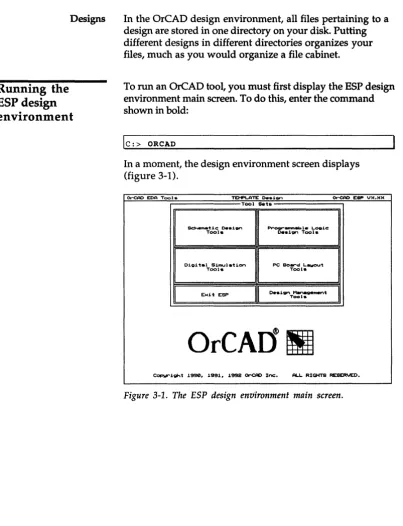
In the OreAD design environment, all files pertaining to a design are stored in one directory on your disk. Putting different designs in different directories organizes your files, much as you would organize a file cabinet.
To run an OrCAD tool, you must first display the ESP design environment main screen. To do this, enter the command shown in bold:
Ie:> ORCAD
In a moment, the design environment screen displays (figure 3-1).
~ EOA Tools TEl'1F'LATE 0..1,;,,, ~ESI"V)(.)()(
Tool Sets
so,.,_·u.c 0 . ... . . , ~_I.L . . . 1c:
Tool. o..1gn Tool.
Digital 5imulati"," PC So ... d L.awout
Tool. Tools
Exit ESP
I
o..1gn ~mentI
Tool.OrCAI1
!II
[image:35.507.63.467.52.579.2]C0F>Wl"1ght 1990. 1991. 1992 <lr'CAD Inc:. AU. RIGHTS RESERVED.
Changing to the
TUTOR design
Before you work with any of the tools accessed from the main screen, you need to change to the TUTOR design. Remember, a design is a directory in which all the files related to a project are stored.
1. Place the pointer on Design Management Tools and click the left mouse button. The menu shown at right displays.
Design Management Tools Execute
Local Configuration Assign Hot Key Configure ESP Help
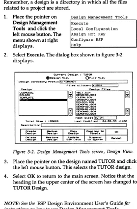
2. Select Execute. The dialog box shown in figure 3-2 displays.
Current o..i~ : TUTOR
f)o..i~ Vi.... O r i l . Vieu
o.si ... Dir.c:tOf"'W Pr-.f'i>< L.:::!C~:'~OR:::C::::f'D=-'~:-:-:-_-:r====:;===::;---I
F" i 1 • • wi I dc: .... d!I,,;;; • .:.,:. SC=-:..H _ _ ----'
De.i... Ott.i~ r i l e .
CUSMODUL. ~ 4BIT. SCH
DCLOCI< ~ BENCH93. SCH
liJtIii .... ii1.IijLA.T.E _ _ _ _ _ _ •
1 DCLOCI<.SCH ~~~~~CH
DEMOF"A1 • SCH
DEMOF"A2. SCH
[i] DEl'1OHA1 • SCH
L - -_ _ _ _ _ _ _ _
...JG
~~:~~Root sheet L.:..!TU=T..::..;OR"'--_-'
Tot.1 Size : 155620 Last Moc:Iif'ied : 04-26-93 11:00
[image:36.504.161.440.91.517.2]o.scription L . , ! _ _ _ _ _ _ _ _ _ _ _ _ _ _ _ ----1
Figure 3-2. Design Management Tools screen, Design View.
3. Place the pointer on the design named TUTOR and click the left mouse button. This selects the TUTOR design.
4. Select OK to return to the main screen. Notice that the heading in the upper center of the screen has changed to
TUTOR Design.
6
NOTE: See the ESP Design Environment User's Guide forPC Board Layout Tools 386+ User's Guide
Changing the startup design
The ESP design environment is configured to the TEMPLATE design each time you run OrCAD tools. Since you will be working in the TUTOR design throughout this tutorial, you need to change the startup design to TUTOR. Follow these steps:
1. Select Design Management Tools. The menu shown at right displays.
Design Management Tools Execute
Local Configuration
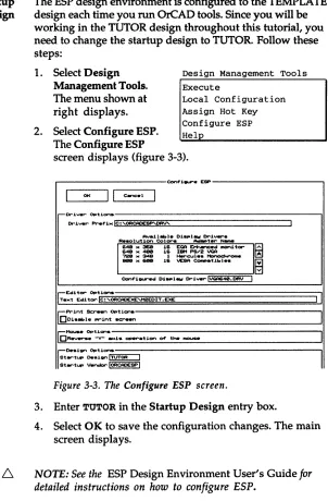
2. Select Configure ESP.
Assign Hot Key Configure ESP Help
The Configure ESP
screen displays (figure 3-3).
Con+"i ... ESP
I
01(II
C.-.c.1I
-Driver Op'tlonsDriver Pref'i .. lc:,OFtCAOESP'DRV'
Ava.U ... I . Di ... I _ Drivers R . . . . lution Col ... _ t ... _
1---
1& EGA Erh.-.c.d monitorI~
64111 .. _ 16 lliM PS/2 VGA 72GI .. 348 1 ... cul • • """lOCI onw
_ .. &I11III
1& VESA eoo.patibl • •
~
Con+"i ... d D i _ l _ Dri..,.,.IV<:A640. DFIV II
r:;:Editor Options
Te .. 't Edi tor Ie: 'OFtCAOEXE""2EOIT • EXE
II
rePrint s.:,...." Options001 .... 1 . . . int screen
[C1'1ouse Options
DR.., ... ltv" .moe!. QPer""atJ.on of' t .... InOI..ISe
[image:37.504.158.460.71.531.2]~o...ign Options Startup o...ign ITUTOR I Startup Vendor 1000CAOESP I
Figure 3-3. The Configure ESP screen.
3. Enter TUTOR in the Startup Design entry box.
4. Select OK to save the configuration changes. The main screen displays.
I
I
6.
NOTE: If you do not want to create the netlistTUTOR386.NET, perform the two steps listed below and
skip to Chapter 4: Introducing Edit Layout. When you load
the netlist in Chapter 6: Placing the TUTOR board, select
TUTORORC.NET as the netlist filename.
If you want to create the netlist, skip the two steps listed below and proceed to Configuring DRAFT and Schematic Design Tools.
1. Select PC Board Layout Tools. The menu shown at right displays.
2. Select Execute. The PC Board Layout Tools screen displays.
PC Board Layout Tools Execute
PC Board Layout Tools 386+ User's Guide
Configuring
DRAFT and
Schematic Design
Tools
Configuring DRAFf
Before you can edit TUTOR386.SCH you need to configure DRAFT to specify the source schematic. You also need to configure Schematic Design Tools to select TUTOR386.LIB as the configured library.
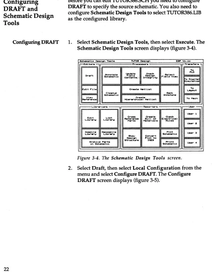
1. Select Schematic Design Tools, then select Execute. The Schematic Design Tools screen displays (figure 3-4).
_ t i c : O'.i,.... Tool. TUTOR O'.i,.... ESP V>c ...
r--Ecli tor .. Proc:es1lOl""s Tr..."f'er ..
-I[I
Dr-~t Sc:heoMItic: Arw-tot.te COntent.(, lJooc:NIt. F'"ield Int .. gritlol O' .. i,.... C ... c:k F'"i .. ld Vi...., Selec:t
~~~t:~1~
er ... t . Nort l i . t To L.awout
Cl ... B~k
Schematic: Annot.t.
I~
er-•• t . I ToMooin f'...-.c:., - - - L . i b r .... i ... Repot""t.,... U . e r
-Edit
EJ
eros. er ... t. C ... c:kL.ibr_1oI Libr-...-w R .. f' ... P .... t . Moot.,..i.l. BlIl of' EI.c:t,..ic:.1 Rul • •
I Us.,.. 2
CompU .. 0.c:~1I .. Plot u...3
L.ibr_!,! L.ib,...,..!,!
Shcu eonv.,..t Sc: ... m.tic: 0..1,.... Plot to
1~~ic:1
Ar-c:h1v. P .... -t. Str-uc::t ... lCE:!iil
in _ t i c : u...4
Figure 3-4. The Schematic Design Tools screen.
[image:39.504.53.469.76.608.2]Configuring Schematic Design Tools
r---Ccnf'J.~ ~---,
OK
II
C-= .. I-I'"U .. O p t J . o n s - : - ; : : : : ; : : : ; : : : : ; ; ; : : = = = = = = = = = = = = = = : : : : ; - - - "
Prttf'J.>c/WJ.I~:~ II.:..' '..:;;-.:.,:' sa-t=.:.. _ _ _ _ _ _ _ _ _ _ _ _ _ _ --'
• '\DEI'1OHf'l2. sa-t ~~
• '-DEI1OHFl3. sa-t ~
.~.sa-t
• VU-LAOO. sa-t
.~AOO.sa-t
• 'I1EMORY • sa-t Iil
;;;;:ow.:R. SCH
B
Sot.rc:.I. , TUT0R386. sa-t 1
;-PI"'oc: . . . 1nQ O p t 1 o n s - - - , 1
OQu1 .. t
-001.-'::101. mc:x..rs.
001 . . . 1 . <Print Sc:r .. t t n ) kttW .f'Unc:t1on
Do.CI""' •• - rnous. .en..i t 1v1 tw
[image:40.505.57.450.62.585.2]DReverse "Y" .a>tis opvr-atJ.Of""'I of' t: .... ffIOUSIIII'
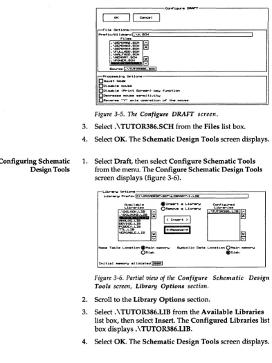
Figure 3-5. The Configure DRAFT screen.
3. Select. \ TUTOR386.SCH from the Files list box.
4. Select OK. The Schematic Design Tools screen displays.
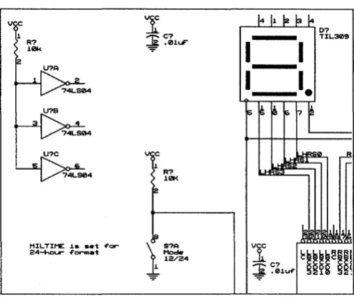
1. Select Draft, then select Configure Schematic Tools from the menu. The Configure Schematic Design Tools screen displays (figure 3-6) .
• :Insert a LJ.brlll"W
ORottnOVtt a Librlll"W
I )
In ... t )I
'I
RII
Conf'i~d
LJ.br..-1 • •
Name Tabl .. Locat1on.Main...,.".." S~olic Data Location
o
Main _P"IooIOru~ .ru~
Initial ...,..". alloc.t .. d~
Figure 3-6. Partial view of the Configure Schematic Design Tools screen, Library Options section.
2. Scroll to the Library Options section.
3. Select. \ TUTOR386.LIB from the Available Libraries list box, then select Insert. The Configured Libraries list box displays. \ TUTOR386.LIB.
PC Board Layout Tools 386+ User's Guide
Displaying the
schematic
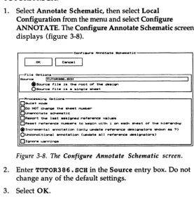
1. Select Draft, then select Execute from the menu. In a moment, the schematic displays (figure 3-7).
MIL TIME i$ $ . t ~cr
24-hour -fermat
1
~C7 [image:41.505.203.457.104.318.2]-=!!
.01uF"Figure 3-7. Partial view of the TUTOR386 schematic.
The reference designators are not annotated and no module values are assigned. These tasks need to be done before you can create a netlist.
You annotate reference designators by selecting Annotate Schematic from Schematic Design Tools. See Annotating the schematic.
Annotating the
schematic
Annotate Schematic scans a design and automatically updates the reference designators of all parts in the design.
Annotate Schematic updates reference designators in the order the parts are placed in the design. You may assign all parts a new reference designator, including any manually edited parts, when annotating the design. To selectively change reference designators and leave others unmodified, use Draft's EDIT Reference Name command.
See Chapter 6: Annotate Schematic in the Schematic
Design Tools Reference Guide for more information about
Annotate Schematic.
Follow these steps to annotate the reference designators on TUTOR386.SCH:
1. Select Annotate Schematic, then select Local Configuration from the menu and select Configure ANNOTATE. The Configure Annotate Schematic screen displays (figure 3-8).
Corrf'".1 ... ArY\ota'tlt so.m_t.1c
I
OKII
C~II
If"·
~
..
-'I
Source ITUTOR3S6. SCH
$Scurc:. f i l . is tM I'"'OOt of tlw . . . i1;ll"\
OSourc. 4'.L1. i • • • .1,...1 . . . t -Pr-oc: ... si~ Options
DQuiet !nOde
000 NOT c~ tlw _ t ~r
D...-..nnot.t. scheMatic
OR ... t tlw last .ssi..,.d r.f..-.nc:_ val ... s
DR ... t: ,...f' ... ...-.c:. ~.,... to begin uJ.th 1 01"\ • .0-. . . . 't o~ the h1ttr"~
@>IncremRntal arnot.tion (onlw UPdat. r~...-.nc: . . . . i _ t ... ~ . s 7)
o
Unc:ondi tiona I arnot.ti..,., (UPdate .11 r.ferenc::e desl_teo-s)D Ignor" • ...,.,.,ine_
Figure 3-8. The Configure Annotate Schematic screen.
2. Enter TUTOR386. SCH in the Source entry box. Do not change any of the default settings.
[image:42.507.173.450.251.534.2]PC Board Layout Tools 386+ User's Guide
4. Select Annotate Schematic, then select Execute from the menu. Processing status displays in a window at the bottom of the screen. The status window closes when Annotate Schematic is complete.
5. Select Draft, then select Execute. The reference designators are annotated for TUTOR386.SCH, as shown in figure 3-9.
vc
2
Rl
10k
U1B
MIL TIME i s set of'or
24-hour" of'or"fI1at
'I
~ el.01uF
R2
101<
\ : SlA
[image:43.507.64.454.64.608.2]J:;
~4Figure 3-9. A partial view of the annotated schematic.
Viewing key fields
Key fields tell Update Field Contents where to look for data. A stuff file, or update file, tells Update Field Contents what module value to insert in the schematic when it finds a match.Update Field Contents uses the preconfigured key field entry in the Update Field Contents entry box of the Configure Schematic Design Tools screen to construct a text string called a match string.
Key fields for Schematic Design Tools are already configured to use the schematic Part Value field and 8th Part Field. The Part Value field is used as the match string that determines what module values go in the 8th Part Field on the schematic.
Follow these steps to view the preset key fields for TUTOR386.SCH:
1. Select Draft, then select Configure Schematic Tools. The Configure Schematic Design Tools screen displays.
2. Scroll down to the Key Fields section.
3. A V displays in the Combine for Field 8 entry box for Update Field Contents. The letter V represents the value in the schematic Part Value field, and specifies the Part Value field as the match string.
4. The number 8 displays in the Module Value Combine entry box for Create Netlist. This specifies the 8th Part Field on the schematic as the field that To Layout checks for the module value when it creates a netlist.
PC Board Layout Tools 386+ User's Guide
Creating a stuff file
Update Field Contents requires a stuff file. You create this text file using a text editor like M2EDIT, the text editor that comes with Schematic Design Tools. If you use a different text editor, use the comparable commands of your text editor.NOTE: Be sure to save this file as text only. Any special
formatting inserted by your text editor may cause Update Field Contents to fail.
Follow these steps to create the stuff file TUTOR386.STF:
1. Select Edit File, then select Execute. The Edit File screen displays (figure 3-10).
Edit F"ile
Wi lck:.,..d L ; . ; I • . . : ; , . • • ~ ______________ - - - I
CU""rent Path: ORCAD'TUTOR F"iles
DEMO.aOl OEMOF"Al.SCH 0EM0F"A2.SCH DEMOHA1.SCH OEMOHA2.SCH OEMOHA3.SCH DEMOHA4. SCH ERC.LST ESP.CF"G F"ILES.LST F"ile to Edit I
Figure 3-10. The Edit File screen.
OK
Cancel
2. Enter TUTOR3 8 6 • STF in the File to Edit entry box, then select OK. The M2EDIT screen displays.
3. Enter the text shown below, including single quotes and upper and lower case characters. Separate the pairs on each line with two tabs.
'10k' 'Reos'
'9.1k' 'Reos'
'.OluF' 'eKOS'
'100uF' 'eKOS'
'47uF' 'eKOS'
'470uF' 'eKOS'
'22uF' 'eKOS'
'74LS04' '14DIP300'
'TIL309' 'TIL309'
'22V10' '24DIP600'
'LM780S' 'T0220'
'9V' 'BAT9V'
'Mode' '8DIP300'
'Reset' 'PBTN2PIN'
4. Select Output to save the text file as TUTOR386.STF.
5. Select Exit to close M2EDIT. The Edit File screen displays.
PC Board Layout Tools 386+ User's Guide
Updating field
contents
You prepared the stuff file, now you are ready to update TUTOR386.SCH by inserting module values into the schematic 8th Part Field. Follow these steps:
1. Select Update Field Contents, then select Local
Configuration and Configure FLDSTUFF. The Configure Update Field Contents screen displays (figure 3-11).
, . . - - - C c n f ' 1 e u r e Up . . . t . 1'"1.leI C o n t t t n t s - - - ,
01(
II
canc.1;.::.~: Opt1cn~!T:~T:;0R;:386;;:::;.
SCH;;:::==============================:::;-,I
*Sour-c:. f"11. 1s the root of" t ... 1gn Osoo.rc:. f"11. 1s a s1r\91. she.t
1'"11 •• :;::;~":rr
ECl..STI'" MEMORY. srr
P()I.£R. srr
TTL.STI'"
Stuf"f" f"1l.!.'TUTOR3B6.srr!
-Proc: ... 1r\9 Opticn .. - - - , I
I'"ielel to be ... eI .. ted
Op ... t Value Op ... t I'"i.ld 3 OP.,.t n.leI 6
Op..-t 1'"1.ld 1 Op..-t I'"ielcl 4 Op..-t nelcl 7
OP .... t 1'"1.ld 2 OP .... t 1'"1.lcI eo . P . , . t 1'"1.ld e
DQu1et moc:le
OCr.at ... uPdate "'.POI"t
e I i t' ! , . . - - - ,
DUnc:ond1tionallw ... d . t . f"1.ld (Nor_Ilw _tuf"f".d onlw 1f" ... tw)
OL • • "e v1.1b1Utw of" spec:1f"1.d f"1.ld ... It ... d . s e t the ... ec:1f"i"d f"i .. leI to vi"ible
OSet the ...,..c:1f"1ecl f"i.ld to 1nv1.1bl.
IIJconv ... t update . t ... .inQ to upp.r-c: . . .
IIIconvert keW f"ield m .. tc: ... tring to upp .. rc: ... DI5N""'tOr. u.,..."insts
Figure 3-11. The Configure Update Field Contents screen.
2. Enter TUTOR3 8 6 • SCH in the Source entry box.
3. Select. \ TUTOR386.STF from the Files list box. The filename displays in the Stuff File entry box.
Checking design
integrity
Configuring Cleanup Schematic
6. Select OK. The Schematic Design Tools screen displays.
7. Select Update Field Contents, then select Execute. Program status displays in the status window at the bottom of the screen. When the process is complete, the status window closes.
8. Select Draft, then select Execute to load the updated schematic. Module values display for each schematic part. These values are inserted in the 8th Part Field.
9. Select QUIT Abandon Edits to return to the Schematic Design Tools screen.
Before you create the netlist, you select Check Design Integrity to check for duplicate objects or overlapping wires in the schematic. Check Design Integrity also creates a report file, then scans the schematic for conformity to basic electrical rules, such as unused inputs and invalid
connections. The three processors in Check Design Integrity are:
.:. Cleanup Schematic
.:. Cross Reference Parts
.:. Check Electrical Rules
Follow these steps to configure the three processors:
1. Select Check Design Configure CLEANUP
Integrity from the Configure CROSSREF
Schematic Design Tools Configure ERC
screen, then select Local
Configuration. The menu shown at right displays.
PC Board Layout Tools 386+ User's Guide
Configuring Cross Reference Parts
C~iQll"e CI ... _ _ tic:
I
01(II
c:..c:.1I
-F'"U. Options
Source ITUT0A386. SCH I
.Source f'11. i . thR root of' thR . . i..., OSource f'11. i • • • ingl. ~t
o..ti,.,.tiOl"lI I
-Proc:: .... ing Options OQui.t IIIOcIIr
DR...,. .,..,..,... ob..!RCt. f'rocIn ~tic: ~t(.)
o " - t of'f'-.rid ... t .
[image:49.504.41.458.67.604.2]o R _ . t CLEFNUP 1f' ~t 1. too 1 _ to _ l . t . 1n _ . . . O X - ...,i.,..
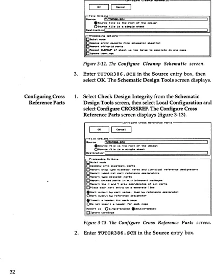
Figure 3-12. The Configure Cleanup Schematic screen.
3. Enter TUTOR3 8 6. SCH in the Source entry box, then select OK. The Schematic Design Tools screen displays.
1. Select Check Design Integrity from the Schematic Design Tools screen, then select Local Configuration and select Configure CROSSREF. The Configure Cross Reference Parts screen displays (figure 3-13) .
. - - - C o n f ' i _ . ero •• R_ ... RnC. P .... t . - - - ,
01(
II
Cane. I-F'"U. Opti ... ~;;;;::;;::==================::;ll Sour-c:. ITUTOR3S6. SCH
eSour-c:. f'11. i . thR root of' thR . . i..., OSourc:. f'11. i • • singl. ~t
o..ti,.,.tiOl"lt
-P,.oc: ••• i.,. Opt i o n . - - - , !
DQu1et mode
Oo.sc.ncj into .",et ... th ... t .
ORepOr""'t onlw twp. miSMatch P .... t • .-d identic.l .... ~.,..enc:. de.1Qnator""s.
DReport ia.n'tical P .... t ,...,..,..enc::: • • • 1gnator.
OR_or-t t _ _ mi ... tc:h .. __ t .
OR.,.or-t unused ... t . in m .... tipl ... t ..
_age.
OR_or-t the X ancj Y grid c:oor-dinat •• of' .11 ... t . OPIac: • • ach ... t Rntrw en • • _ ... t . UneeSor-t output bw ... t ",.Iue. then bW r-ef'otrRn<=. de.ignator-OSor-t output bw ... f' ... enc:.
de.i_tor-e
In • .,...t _ he~ f'cr .ec::h page000 not in .... t . . . f'or-.ack ... _
R.por-t i . O.ingl.-... ac:.d edoubl...--ac:.d
Configuring Check Electrical Rules
3. Enter TUTOR3 8 6 • XRF in the Destination entry box. This is the filename of the report genera ted by this processor. You can view this file using a text editor. If a filename is not specified in Destination, the report displays in the monitor box at the bottom of the screen and is recorded in the ESP design environment
redirection file #ESP _OUT.TXT.
4. Select OK. The Schematic Design Tools screen displays.
1. Select Check Design Integrity from the Schematic Design Tools screen, then select Local Configuration and select Configure ERC. The Configure Check Electrical Rules screen displays (figure 3-14).
r - - - C c n f " i Q U " ' e Ch4tc:k E:1.c:t,..ic:al R u l e . - - - ,
OK
I I
Cancelr--F"ile Opticn~.~~~=============================:ll
Sour-c:e ITUTOR386. SCH
.Sourc:. f'i1e i . the ,..oot of' the de.ign
OSo!....r-c. -File .1. • • single ... t o..tinatiOf'"'lI
r--Proc: •• sinJa O p t i o n s - - - , I
DQuiet II'IOde
DDe.cencl into ... tp.th p . r t .
OUnc:oncu,tion.llW Pf""'OC . . . 11 sheet. 1n des,1Qn DRepo.-t of'f'-""id P .... t ..
DRepor""t .11 ccr'V'Wc:ted 1~1 • .w"ld PQf""t.
ORepOf"""t unc::onnec:'t.d ul ... pins. module port.
OChack mock.Jlti pOf""t c:~tion1i
000 not repor-t ....,.-.nln~
0191'1""'. u ... nJ.ngs
Figure 3-14. The Configure Check Electrical Rules screen.
2. Enter TUTOR3 8 6 • SCH in the Source entry box, then select OK. The Schematic Design Tools screen displays.
3. Select Ignore warnings, then select OK. The Schematic Design Tools screen displays.
L
NOTE: You select Ignore warnings because TUTOR386.SCHhas unconnected pins and Check Electrical Rules will not
PC Board Layout Tools 386+ User's Guide
Running Check Design Integrity
1. Select Check Design Integrity, then select Execute. Processing status displays in the monitor box at the bottom of the screen. When processing is complete, the monitor box closes.
2. If errors or warnings are reported, refer to the appropriate chapters of the Schematic Design Tools
Reference Guide for more information. The chapter for
each of the processors is listed below:
.:. Cleanup Schematic-Chapter 8
.:. Cross Reference Parts-Chapter 23
Creating the netlist
AboutINET
Configuring INET
You use To Layout in Schematic Design Tools to run the processes needed to create the netlist and transfer your design to PC Board Layout Tools 386+.
To Layout runs three processes that update the connectivity database. These processes are INET, ILINK, and IFORM.
INET creates or updates the connectivity database for the design. See Chapter 9: Creating a Netlist in the Schematic
Design Tools Reference Guide for more information about
this processor.
1. Select To Layout, then Configure INET
select Local Configure ILINK
Configuration. The Configure I FORM
menu at right displays. INET on
INET, ILINK, and ILINK on
IFORM are set to on by I FORM on
default.
2. Select Configure INET. The Configure Incremental Netlist screen displays (figure 3-15).
r---Conf'~ ... %nc:..-nt.1 _tl~.t---..,
I
OKII
C~.II
~
F"U" Opt.l.on. Sourc::. ITUTOR386.SCHReport. o..tinetion I
: I
,...-Proc: .... "ing O p t i o n s - - - , I
DQui.t MO.
Do...C:end into _.tpatt-. P .... t .
DA •• ign 8 net n _ to 811 pins DReport of'f'-grid P .... t ..
D R _ t all COf'Y'ec::t ... 1 _ _ 1 ... .,.,...t.
OR-.oort YnCOf'"V""MtCt.d u.1r.s. pins. f'nOdul. PQr"'t.
DRun ERC on all
_.t.
proc • • • • d[Is I p I i .
DChec:k MO.a..l. port connections DRebuHd .,.U • • tack
DUnc:oncU.tionall", proc • • • all ... t . in • • ign
000 NOT cr •• t • • X....,. 4'il... (R..,.,...t onl",)
DProc: .... one _ . t onl", (Thi. 4'orc: . . ReIoulld 4'.lI • • tack on .... ><t ... ) DInc:lude ... d .ignal. connect.d to modul. P .... t .
D u . .
,....,..renc: ...
ignator •• _ t _ "'or _ t P . t t - . P .... t . D R _ t _ t " , ....,.a,,1. ".1 ...D Ianor--e u..-nlne_
PC Board Layout Tools 386+ User's Guide
AboutILINK
Configuring ILINK
3. Enter TUTOR3 8 6 • SCH in the Source entry box.
4. Select OK. The Schematic Design Tools screen displays.
ILINK creates the intermediate netlist structure and the linked connectivity database. This database contains information on connectivity, parts, fields, pin typing information, and layout directives.
See Chapter 9: Creating a Netlist in the Schematic Design
Tools Reference Guide for more information about this
processor.
1. Select To Layout, then Configure INET
select Local Configure ILINK
Configuration. The Configure I FORM
menu at right displays. INET on ILINK on
2. Select Configure I FORM on ILINK. The Configure
Netlist Linker screen displays (figure 3-16).
Cc>n4'~ _ _ Not~I1.~ L~"""' ....
I
01<II
CancelI
r;:,...t.le Opt.t.cn.So<.rc:e ITUTOR3B6. It#"
II
r-Proc: . . . ing Opticns
DQu~.t IfIOcIe
DF"orc:. ILIN< ~o . 1 _ Ii ... U . . . t-. ••
D R _ t .ingle ,.,.~ node.
o
Ignor-e u...."ingsFigure 3-16. The Configure Netlist Linker screen.
3. Enter TUTOR3 8 6 • INF in the Source entry box.
AboutIFORM
Configuring IFORM
IFORM uses the netlist format file and an intermediate netlist structure created by ILINK to create a netlist in the format you define. EDIF is the netlist format used in this tutorial.
Follow these steps to configure IFORM so it produces a netlist in EDIF format:
Configure INET
Configure ILINK
Configure IFORM
INET on
1.
2.
Select To Layout, then select Local
ILINK on I FORM on
Configuration. The menu at right displays.
Select Configure IFORM. The Configure Netlist Format screen displays (figure 3-17) .
...---Conf'1~ _t11.t F " o n n a t - - - .
I
OKII
can:. II
@
F"1Ie Opt1ons
Sour-ce ITUTOR396 I
I
:_tlnetlon '71'EITU~T§0R3S6§::::=:.N£T::==================-'1
.!: l i t1 e I I
Selected f" ... t: IF"EDIF".E:XE I V ... 1on: 1.10c: 28 _ _ -93
DQuiet mo.
DF"...-c:e IF"ORH to al..-- eNtate a f"onnatted .... tI1.t
o
ISInOI""t' u..-ninv.,-F"onnat Speclf"ic O p t l o n . - - - . I
o
Do not - - - - ' _ t I'1UIIIber to I _ I .D Do not outPUt additional _ t i e .
III OUtPUt pin ... (instead of" pin ... )
o
Do not cre.te t .... ·_t....".l· U b r _ . c l ... tionPC Board Layout Tools 386+ User's Guide
Running
To Layout
Viewing the nellist
3. Enter TUTOR3 8 6 in the Source entry box.
4. Enter TUTOR3 8 6 • NET in the Destination 1 entry box.
5. Select FEDIF.EXE in the Netlist Format list box. The filename displays in the Selected Format entry box.
6. Select Output pin numbers (instead of pin names) in the Format Specific Options section.
7. Select OK. The Schematic Design Tools screen displays.
Now that you have configured all of the necessary To Layout processors, you are ready to run To Layout and create the TUTOR386.NET netlist.
1. Select To Layout.
2. Select Execute from the menu. INET, ILINK, and IFORM process sequentially. Processing status displays in the status window at the bottom of the screen. When To Layout is done, the netlist file is created and the PC
Board Layout Tools screen displays.
Follow these steps to use M2EDIT to display the netlist. If
you have a different text editor configured, use the comparable commands of that text editor.
1. Select Edit File from the PC Board Layout Tools screen, then select Execute. The Edit File screen displays.
2. Select. \ TUTOR386.NET from the Files list box. The filename displays in the File to Edit entry box.
Summary
(edifUersion 2 8 8) (ed itLeue I 8)
(keywordtlap (keywordLeue 1 8» (status
(written
(ti~StaMp 8 8 8 8 8 8) (pl'OgraM "IFORn.EXE")
(cOlUlent "Original data froM OrCAD.lSDr schenatic"» (co .... ent "Digital clock scheMatic")
(co_ent .. ~pril 23, 1993") (cOMlllent .... )
(co ... ent .... ) (co_ent .... ) (coMMent .... ) (co ... ent " .. ) (COMMent .... ) (COIIIMent n,,»
(external OrCAD_LIB (edifLeuel 8) (technology
(nuMberDefinition
(scale 1 1 (unit distance»» (cell ICAP
(cellType generic)
(colIIMent "Fro ... OrC~D library TUTOR3B6.LIB") (uiew HetlistUiew
(uiewType netlist) (interface
(port 11 (direction IHOUr» (port 12 (direction IHOUT»») (cell IR
(cellType generic)
(colIIMent "Fro ... OrCAD library TUTOR3B6.LIB")
Figure 3-18. Part of the TUTOR386.NET netlist.
4. Select Exit to close M2EDIT without making any changes to the netlist file. The Edit File screen displays.
5. Select Cancel to close the Edit File screen. The PC Board Layout Tools screen displays.
In this chapter you updated schematic reference designators using Annotate Schematic. You created a module value stuff file and inserted module values into schematic part fields using Update Field Contents. You also created a netlist using the processors in To Layout.
I
n
fro
due in
g
E
d
if
Layout
PC Board Layout Tools 386+ uses the Edit Layout editor to create the board layout. As its name suggests, Edit Layout routes your layout both manually and automatically.
Edit Layout is designed to support the complete PC board layout
process
from netlist to high-resolution output. Edit Layout stores the information on the computer's disk as a data file.Edit Layout saves the board file in the design in which you are working, or you can save it to another directory. The board file can have the design name and an extension of .BD1, or you may give it a different filename and extension.
In this chapter, you learn how to:
.:. Change default configuration settings
.:. Change view and display options
.:. Save, copy, and rename board files in Edit Layout
PC Board Layout Tools
386+User's Guide
Configuring
PC Board Layout
Tools
You configure PC Board Layout Tools to define the working board file, current device drivers, available module libraries, file paths, and default file extensions.
After completing
Chapter
3:Transferring from schematic to
layout,
the PC Board Layout Tools screen displays(figure 4-1).
PC Bo.-d Lawout Taol. TUTOR Deaien ESP
\hc._
E . U t _
Edit L.-...t
L.ibr-.... i ...
~.
L.ibr-...-w
.----Pr-c:oc:ea_-Modif'w
... 1 • •
R.~t.t.
Boar-d
~il.
er •• t.
NC Drill
~il.
~i)(
Ti ....
St _ _
C o m p
-Netlist.
Figure 4-1. The PC Board Layout Tools screen.
u ...
u..,. 3
Follow these steps to configure PC Board Layout Tools:
r - - - C o n f ' 1 _ e PC eo.rd L A w o u t - - - ,
01( " c . w : e l
I
,.Dr1ver O p t 1 " " ' . - - - . 1
Dr1ver _1>< Ie: 'ORCACESP"'CB~IVER'
Av_J.l . . le 01 ... 1_ Dr1ver.
R • • olu'tion ColOf""'. ~t.,... N...,.
I~'-
..
,-p~=
II
Conf'l_ed Oi_I_ .. Dri" .... !~4(!I.ORV I
Av_il . . le Print .... Drivers
M.nuf'..:::turer Hodel Re.olution
1-
y~wn 'yU_ p - > - •-I!
Conf'iQUNtd Printe ... Dri" .... !I-FLASER4.ORVI
Figure 4-2. Top of the Configure PC Board Layout screen.
2. Select a display driver for Edit Layout from the Available Display Drivers list box. The driver filename displays in the Configured Display Driver entry box. If you want to use a custom driver that is not listed, enter its filename and extension in the
Configured Display Driver entry box.
3. Select a printer driver for Edit Layout from the
Available Printer Drivers list box. The driver filename displays in the Configured Printer Driver entry box. If
you want to use a custom driver that is not listed, enter its filename and extension in the Configured Printer Driver entry box.
6
NOTE: You must select a printer driver if you want to printthe TUTOR board in Chapter 9: Printing and plotting the
PC Board Layout Tools 386+ User's Guide
4. Enter the path foryourTUTOR design directory in the Library Prefix entry box~ The module libraries you use in this tutorial are stored in TUTOR.
If you use the default directory structure, you enter
C : \ ORCAD 'TUTOR \
* .
MLBin the Library Prefix entry box.If your TUTOR design directory is located in a different path you must enter the correct path, using the format shown in the example above.
6
NOTE: It is important that you enter the proper path so youcan follow the steps in this tutorial.
1..11 ... 101 """f"1>< IC:.'ORCAD'TUTOR' •• I'LS
Av.U ab Ie
.J ...
t .I..U:ir....".1..1br .... l . . OR...w. .• · L.(br....".
• '\OEt1O; I'LS ~
~:a386.tUl~
I
~ 1 ... · ·.t )I
...•
. .r-.P .... f"b( Optlcns~:;;;;:;;;;;;;;;;=====================;~-ll eo .... d f"U ... f"l)(a:le::;::'~ORCI'ID~;il;i'TUT?::EOR~'==============l
I
Ne1:l1st ... f"l><lc:'ORCAD'TUTOR'
T ... f"U ... f"1><1
p
Vlr"'tUlOl ... 101 OptionsDlr"'ec:tOt"'w Ie:,
F"1I.1~SWAPF"5;:;;IU::::';;=:;;. TMP~I---'
Figure 4-3. Bottom of the Configure PC Board Layout