INFORMAL DESCRIPTION OF THE
sec
6700
Butler W. Lampson
University of California, Berkeley
Document No. W-4l
Issued March
6, 1968
~Contract SD-l85
Office of Secretary of Defense
w-41
INFORMAL DESCRIPTION OF THE
sec
6700The Scientific Control Corporation
6700
is a large-scale general purpose co~puter specifically designed fo~ time-sharing. It isthe product of a joint effort of Project Genie and SCC personnel. One of these machines, together with accompanying drums, disks and memory, has been ordered by the project. It is hoped that· the system will be operational by the first quarter of
1969.
This document is an informal reference manual for the machine. It describes the overall system organization, the CPU, the
memory system and the input/output at a level of detail which is intended to be the maxtmum of what a systems programmer might want to know and what is currently decided. It is not to be taken as certain truth.
Overall design, Main memory
'~ne
6700
is a memory-centered system. It consists of alarge number of more or less independent devices which communicate with each other primarily through memory. There are a few other channe ls of communication: the ACT bus, the PRO bus and wakeup lines.
The main memory of the system is 128K (expandable to 512K) of core organized into 8 module s of 16K each. The cye le time of the memory is 1000 ns; the read access time is 400 ns. The , 'memory is 52 bits wide; there is room for 2 of the machine's
24-bit words and
4
parity bits.Each module of the memory is connected to a fast memory which consists of six address regi~ters and six double word
data registers, one for each address register. All communication between the outside world and the core takes place through
the fast memory.
Each fast memory has four ports, i.e., four independent
~-bit words and control information. A device references the memory by presenting an address and six control bits, which are used in the following way:
One bit is a memory access priority bit. I f it is on, the request has high priority for access to the fast memory. This means that if another fast memory request is presented to the module in t~e same'cyc1e (100 ns) Which does not have the memory access priority bit set, 'the request which does have the bit set will win. The
other request can be made again in the next 100 ns cycle. If two requests have the same memory ~ccess priority, the one is chosen which comes in at the port having the highest priority. The priorities of the ports are fixed.
Two bits specify the core access priority 'as Low, Warning, Medium or High. If the request requires a core, access, these bits determine how it fares in competition with other requests requiring core accesses. W 1s
- ... 'livalent to L except that it causes any pending W , ltquests to be converted to H ; it is used by -the drum
transfer unit.
Three bits describe the nature of the request. They are called Fetch, Store and Hold. Five combinations of these bits are normally used:
F S H
o
0 1 Pre-store. Obtains a register in fast memorytor the address and sets its hold bit. The register will not be released, unless its hold bit is cleared by another request with the same address, until 10}-AS has elapsed. No core reference is initiated by this request.
3
-o
1 1 Store and hold. Same as store except that the hold bit is set •. 1 0 1 Pre-fetch. Obtai~s a register in fast memory for the address and sets its hold bit. The memory will make a core access if necessary to make the data portion 'of the register agree with the contents
ot
core.1 0 0 Fetch. I f data is ready in the fast memory, it is transferred to the bus. The hold bit is cleared .
. ' Each module of 'the memory listens to requests at its four ports in every 100 ns cycle. It accepts at most one request; the others are rejected within the same cycle~ It a request is
accepted, data and addresses are transferred in the follOwing cycle. Thus, an accepted request takes 200 ns, a rejected one 100 ns. This is not a complete description of memory bus timing.
Tbe fast memory attempts to keep its contents in agreement with core, doing fetches or stores from core as necessary.
If
the ~(~ory is left alone for six cycles, it will be able to make aU"ine core references it needs. "'lhere will then be 48 double words in fast memory. They will stay there until displaced by later requests. A program operating in a tight loop on a small , .volume of data may be able to,approx~ate this sit~ation quiteclosely.
The follOwing devices are attached to the main memory: The CPU
The drum and dis~ transfer units
The drum and disk controller (AMC or auxiliary memory controller)
The process control unit (pcu)
The character input/output controller (CHIOC)
Any other
I/O
devices which may be attached to the system. There 1s an ACTivate bus which connects the CPU to the twocontrollers, the FeU and any other I/O equipment which may be attached. There is also a PRotect bus which connects the CPU,
. .
the
FeU,
the controllers and any other device which needs to set. ,
4
-The CPU
We will discuss the capabilities of the CPU under the following headings:
addressing and mapping instruction set
input/output
Because of the highly interdependent nature of the system it will be necessary-to use certain terms which are not defined until .later in the discussion.
Addressing
Each process has available to it a 2t19 word virtual memory which is divided into 32 units of 16K words each called chunks. A full address is therefore 19 bits, divided into a 5-bit chunk number and a. l4-bit word address within the chunk. A 19-bit field can be interpreted as a full address in the following contexts:
1\ As part of an indirect address word.
~ t ¥~
2) As part of the X register during indirect ~ddressing or in executing LFB or SFB.
3) As part of a word in a pop transfer vector.
4)
As the operand of BRR or XCI or BSR.Since case (1) is by far the most· important we will consider it
in detail and then point out the ways in which the other cases differ.
An indirect address word has the following format:
o
1 2 3 4 5 23w ..
I
II
XI
XpI
TRI
FAI
full addressI
The I bit specifies another lev~l of indirection. Tlie X bit specifies indexing. The TR bit specifies that a tra.p should
-- .
-occur. The FA bit specifies that this level of indirection
provid~s a full address. The XP bit specifies that the X
.. -. --...
5
-Indirection proceeds in the following manner. If W has been retched as an indirect word from address Q:
Trap if' TR = 1 (see below)
Set,WA
=
W10- 23 if X=
0, W10-23 + X10_~3 if' X=
1 Set ~N = ~-9 if FA=
0W
5
-
9
if FA = 1 and XP = 015-9-
if' FA = 1 and XP = 1The effective address at this level is (CN, WA), by which
we
mea.n the 24-bit quantity:o
4 5
I
eN
9 10
I
WA
23
[ 0
If' I
=
1, we use this word as the address or another indirect word. Otherwise, we return it as the effective address.The effect of all this is that if FA = 0 indirection pro~p.e.s.~ exactly as in the
940,
except for the different'. ,. -
-arrangement of the bits and the presence of the tra.p bit. The address ~roduced is in the same chunk as the indirect word.
I f FA
=
1, the address produced is in a different chunk, either the one specified by the indirect word or the one specified by X, depending on the setting of XP.An instruction word has the format:
0 1 2 3 4 9 10 23
ADDR
If P
=0,
the OP field specifies one of 64 instructions to be executed. Every instruction without exception generates an effective a.ddres·s in the same way:, '1) Let CN'
=
r,-9
(chunk number of the location counter) '2) Let WA = ADDR if X=
0, ~DR+Xl0_23 if X=
13) Go indirect through the address (CN,WA) if I = 1.
- ,
.6
-Note that this is equivalent to trea.ting the instruction word with bits
2-9
cleared as .an indirect word •. Once the effective address 'Q ha~ been generated, execution of the instruction depends on the P and OP fields. This subject 1s discussed in the next section.
Addressing from one chunk to another is controlled by a
32
X'32
matrix called the inter-chunk protection (ICP) matrix. An entry in this matrix contains two bits and determines thelegal.ity of an inter-chunk reference as follows:
o
no access is allowed 1 read access only2 read and indirect access
3
any kind of accessA ref'erence made to obtain a word used in indirection is an indirect reference. A reference made to obtain an instruction 1s an execute reference. One made to fetch an operand is a read reference, and one made to store a data word is a write reference. The entry of the Iep matrix to be used in checking
, ~,~.
the "lee ~.ity of a reference is ~ ... terrr,ined by the chunk containing the word which provide the address (source chunk) and the chunk. containing the word addressed (target chunk). Thus, in the sequence
{:
LDA*
Nchunk Kl.
IA.*
01, 02 this is an indirect address directive. The operands are chunk number and word address respectively.chunk O~ 0 IA Pl, P2
chunk PI P
DATA
24
.execution of the instruction at M loads
24
into A provided . Ml has indirect access to 01, or ICP[Ml,Ol] ~ 201 has read access to PI, or ICP[Ol,Pl] ~ 1 Note that the value of fCP[Ml, PI] is not
i:ll
question •7
-empty - no real memory corresponds to this virtual memory a real page reference
an,indirect page table reference
If the value is a real page reference, it has "two parts: a drum address which specifies the page and three protection bits:
W, X, P.
Wallows writing into the page if it is on.
X allows instruction words to be fetched from the page if it is on.
P allows privileged instructions to be fetched if it is on. Note that the protection bits are associated with the entry for . . the page in the map and ~ with the physical page itself.
Converting a full address (CN,WA) into a physical address requires the following steps:
Obtain the CNth entry from the chunk table for the process. This tells where the page table for chunk CN is and what its nominal page size is. Call the NPS P.
Obtain the (WA!P)th word from the page table.- If its value 1s a real page, this givo~ Ub a drum address for the l)8.$le.
. t:'"
Look up D in a hash table called J?HT. If it is there, the associated information tells where the page is in core and what state it is in.
This process is described in complete detail below.
I f the value of a virtual page is
an
indirect page table reference, it also has two parts: an actual page size<
the NPS and an address which tells where to find a small page table containing real page pointers. I f the NPS is 1024 and the APS is256,
the small table contains four ~ntries for four256
word real pages which make up the 1024 word nominal page. Each of these entries is 0 or a real page reference.8
-Each process has a 32-word chunk table; one word of this table either contains 0,. indicating that no memory is assigned to t~e chunk, or points to the pa.ge .table for the chunk. The format of a page table pointer is
o
13 4 5
12 13BPS . = nominal page size for this chunk. This number determines the division of the word address into page number and word in page. -The nominal page size is 32
~
2NPS, and NPS ranges between 1 (64 words, not implemented) and 6 (2048 words). BPS=
7 is-reserved.23
A
=
absolute address bit. PrA is interpreted as an absolute address if_this bit is set, as an addressin the context bloCk if it is clear •
. PI'L = length of page table (in words) -1.
PTA
=
address of page table, modified by A.A page table starts with four words which contain one row
~~ the
Iep
matrix, packed eight entries per word, two bitsper entry in the bottom l~ bits. The interpretation of an entry is:
00 - no access 01 - read only
10 - read and indirect 11 - free access
describing access ~ this chunk to another one
The remainder of the page table, PTL words of it, contains
[image:9.620.102.517.58.688.2]9
-An empty entry is
o.
A real page reference has the formo
13 4
6
7 23I
0I
PPB SPN DRUM ADDRESSI
PPB
=
page protection bitsbit 1
=
P: privileged instruction authorization bit 2=
X: instruction fetch authorization· bit 3 = W: write authorizationReading is always allowed
S~ = sub-page number. See the discussion of real address formation below.
An indirect page table reference has the form
0 1 3 4 5 12 13 23
1.
11
APSI
A
I
unusedJ
PrA
I
";I, " • ~4.
.
APS = actual page size
-A, Pl'A have the meanings ascribed above
- This entry points to a small page table with page size specified by APS. This table has only· empty or real '9age entries. It contain NPS/AP~ words. We require APS < NPS.
There is a hash table called DHT which keeps track of
the. drum pages which are in core. The key is the drum address. A linear collision doctrine is used. An entry in this table occupies two words and has the form:
o
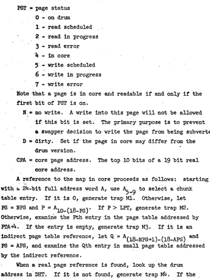
2 3 4 6 7 23 0 12 13 14PST = page status
o -
on drum1 - read scheduled 2 - read in progress
3 -
read error'4 -
in core" - write scheduled
6 -
write in progress7 - write error
Note ,that a page is in core and readable if and only if the first bit of PST is on.
N ~ = no write. A write into this page will not be allowed if this bit is set. The prima.ry purpose is to prevent a swapper decision to write the page from being subverted. D
=
dirty. Set if the page in core may differ fram thedrum version.
CPA = core page address. The top 10 bits of a
19
bit real core address.A reference to the map in core proceeds as follows: starting
• • ¥t- •
-with b 24-bit full address word A, use ~-9 to select a chur~
table en~ry. If it is 0, generate trap Ml. Otherwise, let PS
=
NPS and P=
A10-(18-PS). If P> LPT, generate trap M2. Otherwise, examine the Pth entry in the page. table addressed by ~+4. If' the entry is empty, generate trap M3. If' it is an indirect page table reference, let Q=
A(18-NPS+l)-(l8-APS) and PS=
APS, and examine the Qth entry in small page table addressed by the indirect reference.When a real page reference is found, look up the drum address in'DHT. If it is not found, generate trap
M4.
If the first bit of PST i~ the entry found is 0, generate trapMD.
Otherwise, compute the real address asCBA*2
9
+SPN*2
6
+A(18_PS+l)_23
.Note that the + signs may be taken as merge rather than add because of the way in which these quantities are obtained.
A reference to the map must specify whether the address is
< , to be used for writing. If' so, D is turned on in the DHT entry
[image:11.621.112.525.51.596.2]11
-Since it is not acceptable to subject every memory reference to
this
time-consuming process, the machine is equipped with eight associative registers to hold information about the most recently used core pages. One of these registers has the form:0 2 3
78
14 15 27 28 30 31I
ps CN PN CPAPS = page size. Same code as for NPS above.
CN
=
chunk number. PH = page number.PPB D
I
CPA = core page address/64. Bit 27 is set to 0 permanently. PPB
=
page protection bitsD
=
dirty bit from DHTWh~n
an
address is presented to the map unit, an association is done on theeN
and PN fields of each register. The bits of the address used in this association are determined by the PS field.If" the l.ssociation is successfl,;,~" tht:: real address is computed
l
as CPA*64 merged with the bits of the address not used for the association. The PPB field is also returned so that the processor can check the protection.
With the address must come a bit which specifies whether a load or store is being done. I f the latter, D must be set when the association succeeds. othe~se, that register is cleared and the map unit proceeds as though association had failed.
,
~is is t~ ensure that the D bit in DHT is set whenever a store is done. The final state of D is returned.
- If the association fails, the core map is referenced using the algorithm described above. If it is successful, an associative register is· chosen and its former contents erased, and its
fields are ·set from the results of the reference to the core map: PS +- PS computed during map reference
eN
+-"'5-9
CPA +-CPA in the DHT entry
*
8 + SPN. PPB +- PPB in the page table entry D +-D in the DHT entry
In parallel with the association for core address is one tor lCP bits. There is another set of registers of the form:
o
4 5 6 7 9 11 13 15 17 19 21·_I_S_C~~~
__
~E~ol~El~I
__
E2~I
__
E_3~E_4'~_~~I_E6~I~E~71
SC
=
source chunk numberTC = top, two bits of target chunk number
Ei
=
lCP [SC,TC~+ilI.e., if association on SC and TC succeeds, the last three bits of the target chunk number are used to select the proper Ei.
If association fails, a reference to the core map must be made. The page table for chunk SC is found .as before, and
PTA+TC is fetched.
The overall function of the m~p 13 described-by the following table:
Input Output
Source chunk
se
lep bits (2)Target chunk TC PPB (3)
Target word address WA Real core address (19) Load/store indication D bit (1)
..
There is an ACT instruction for the map-loader called CVRA Convert VirtUal'to Real address It accepts one argument, namely a 19 bit virtua1 address, and returns either:
--a) A noskip if the page containing this address is not in the map, or
- b) a skip and
1) The drum address of the page
. 13
-in DHT
3) 'The real ~ddress corresponding to the virtual address if the page is in core, or 0 otherwise.
In
other words, this instruction makes available most of the results of the mapping operation, so that the processor does.
14
-InstructionsWe will describe the 6700 instruction set in terms ot its differences from that of the
940.
Notation: L = 24-bit program counter, Q=
24-bit effective address, (Z) means contents of memory location addressed by Z. Needless to say, all addreSSingis. mapped •. Assume L ~L+l in every instruction descri~tion unless otherwise stated. Any add to L or Q is a 14-bit add; the chunk number is unaffected.
General
1. The format of an instruction word is different. See
~ow.
2~ The effective address is computed in exactly the same way for every instruction.
3.
Indirect addressing is handled quite differently. See above.Symbols
L
=
24 bit location (program) counter: . A,3
jX
= A,B,X registersQ
=
24 bit effective address OV=
~verflow bitCO
=
carry bit from 24th bit of adder. Also used by floating ]Oint instructions.15
-Loads and Store s
New instructions:
XMX Exchange memory and X
X ... (Q) , (Q) -+ X
STM Store masked
(Q)I\
B
V AI\ B -+ (Q,)I.e., store the bits of A selected by 1 bits in B.
LDD Load double
(Q) -+ A ; (Q,+l) -+ B
STD Store double
A -+ (Q,) ; B ... (Q.+l)
STZ Store zero
16
-Field Instructions
There are six new instructions used to load and store parts
. .
of :words in memory. They allow convenient ha.ndling of fields' from zero to twenty-four bits in length arbitrarily positioned in either a.. single word in memory or two adjacent words. These instructions all make use of a common "field descriptor" or pointer word to control the field to be loaded or stored.
The field instructions expect the word at the effective address to be a. word of the following format:
o
'4
5 9 10 23I
OFF51
,
--ADR
This word is called a "field descriptor" or "FDIt and defines
. a contiguous field in memory from zero to twenty-four bits in length.
~G - A five bit integer which defines the length of the field. LNG must be equal to or less than
24
in the sta.ndard case. Specifica.tion of a length greater than this will cause a tra.pG4
whenever the FD is referenced. An LNG value of 31 (37 octa.l) is a specia.l case to be described later •. OFF - A five bit integer which defines the offset of the field from the left side of the word addressed. The value of OFF must lie between 0 and 23 inclusive or trap G4 will occur. Bit 0 is the left (high order) bit of the word a.nd bit 23 is the righ~ (low order) bit of" the word. An OFF value of 31 (37 octal) is . a special case to be described later.
ADR - A fourteen bit integer which is the memory address
17
-Although these instructions will most frequently be used to handle eight bit (or six bit) characters packed three (o~ four) to a word, they are explicitly intended to handle arbitrary fields which ma.y overlap word boundaries in any way.
, )
In order to avoid repetition in the following instruction descriptions, the setup common to all six field handling
instructions will be described here.
. 1. (Q)~O-23 -+ ADR, (Q)5-9 -+ OFF, (Q)O~4 -+ LNG
2.
5-9
suppress this for LOFI and STFII f OFF = 378, (X) -. OFF
J
.
3. If' LNG = 378, (X)O_4 -+ LNG
-4.
I f OFF>
23, generate trapG4
5.
'If LNG>24,
generate trapG4
6.
OFF -+ I, OFF + LNG -1 -+ J, 23 - LNG+l -+ KThat is, the contents of the effective address are separated into their component pieces. If either the offset or length
< 'is
31
(378), the value is taken from the correspon~ing part of the in~ex register. The offset and length are then checked to be sure they are within limits.
Finally, the left and right bit numbers of the field in memory and the left bit number of the field in the A register lU"e computed. In the following descriptions (ADR)I_J means
(ADR, ADRH)I_J if J> 23.
'LDF Load Field
o
-.A, (ADR)I_J -+~-23The field described is right aligned in the A register. The remainder of the A register is cleared.
, . .
STF Store Field
.Ax-23
-+ (ADR) I-J18
-LDFB Load Field Based
ADR + X
10-23 -+ ADR
if X4
=
1 use ~-9 as chunk number for datao
-+ A, (ADR) I-J -+ ~-23This instruction is the same as LDF except that the contents of the address field of the index register are added to the F.D address before the field is loaded, and the chunk number for the field may be taken from X.
STFB Store Field Based
ADR + ~O-23 ~ ADR
if X4
=
1 use ~-9 as chunk number for dataThis instruction is the same as STF except that the contents of the address field of the index register are added to the FD address before the field is stored, and the chunk number for the field, may be taken from X.
LDFI Load Field and Increment
I f [(Q+l)lO-23 - ADR]
*
24 + (Q+l)5-9 - OFF<
ING no action,otherwise (Q)5-9 + ING2 -+ (Q)5-9 (if ~ 23)
else .(Q)5-9 + LNG2 - 24 -4 (Q)5-9' (Q)lO-23 + 1 -} (Q)lO_23
IC+2-+IC
'.0 -+A, (ADR)I_J -+ ~-23
: - . "
.The contents of the effective address and contents of the next location are both considered to be FDts. The second of these
. _ _ _ oa._~~
19
-effective address is adjusted by the length
of
the field defined,, ,
the field is loaded into A and a skip occurs to signify that the tie1d was loaded. This special test for LNG or OFF fields equal
to-
378 is suppressed.STFI Store Field and Increment
I f [Q+l)lO-23 - ADR]
*
24 + (Q+l)'_9 - OFF<
LNG, no actionotherwise, (Q)5-9 + LNG2 ~ (Q)'-9 (if:5 23)
,else ~Q)'-9 + LNG2-24 -: (Q)5-9' (Q)lO-23 +1 ~ (Q)iO-23
LC+2~IC Ax-23
~
(ADR) I-JThe contents of the effective address and the contents of the next location are both considered to be FD's. The second of these words is a limit. I f there is insufficient room for
the field, no action occurs. Otherwise, the FD'at the effective address is adjusted by the length:
of
the field defined, the 'right most LNG bits in A are stored in the designated field,and a. skip occurs to signify that the field was stored.
IFD Increment Field Descriptor
It [Q+l)lO-23 - ADR]
*
24 + (Q+l)5-9 - OFF<
LNG, no actionOtherwise, (Q)5-9 + LNG2
~
(Q)5-9 (if~
23)e~e
.(Q)5-9 +LNG2~24
-+ (Q)5-9'(Q)~O_23+1
-+ (Q)lO-23IC + 2 -+ (ADR)I_J
Arithmetic
1. ADD and SUB do not affect XO. Instead there is a carry bit CO which is 'set or reset by the carry from bit 24 of the adder on ADD or SUB. Both instructions take CI as a carry into bit 0 and reset it. Cl is set only by the CCB instruct ion in the perform group and by BTO. When CCB
is executed, CO is copied into Cl. Multiple-precision arithmetic 1s done by adding (or subtracting) the least significant words and then doing CeB before adding the most significant words. This causes the carry from the sum of the least significant words to be added into the sum of the most significant ones. Unless
ceB
is executed,cr
will normally remain0
and will not disturb the operation of the machine.2. MUL leaves the sign and most significant part in B, the least significant part in A. I.e.
1eave~
0
in A.LDA ~ 2 MOL =
3
3.
DIV takes the 48-bit AB register as an integer dividend, (~) as an integer divisor. The integer quotient appears in A, the remainder in B. On overflow ( , (Q) r ~I
AI)
OV is set andAB are unchanged.
New instructions:
MDE
Memory decrementADX
(Q) - 1..-. Q
X + (Q) -+ X
21
-Floating Point Arithmetic
. Al1 these instructions are new. They take two-word floating point numbers as arguments. The forma.t of So floating point
DUlllber is
o
38 39I
FRACTION EXPFRACTION is a two's complement fraction with the bina.ry point between bits 0 and 1.
EXP,is a ~wo's complement exponent in the range
(-4008' 3778).
47
Al1 floating point instructions except UFAD and UFSB expect normalized operands and produce normalized results. FAD and FSB
. .
will correctly post-normalize a result produced from unnormalized operands. FMP and FDV will not work properly on unnormalized operands.
lt an exponent overflow occurs in any floa.ting point operation, trap Gl is generated. The result left in AB is correct except that the sign bit of the exponent is wrong; the correct sign bit is the complement of B15e
I f an exponent underflow occurs in any floating point operation, trap G2 is generated. The result is correct with the exception stated.
All floating point opera.tions in this section set the carry bit CO. None sets the overflow bit.
All arithmetic is unrounded. The most significant fraction bit not included in the result is saved" in
CARRY.
An instruction is provided to do rounding.In
addition to the instructions listed here,FLT, FIX,
FAD
Floating addAI?
+ (Q,Q+l)F ~ ABF. .
The result is always normalized. Exponent overflow or underflow may occur. Arithmetic 'is done in a 48-bit adder, and,
48
bits are kept until the result is packed, at which point the first bit discarded is saved in CO for use in rounding.FSB
Floating subtractABF - (Q,Q+l)F ... ABF
See FAD
UFAD Uhnormalized floating add
(unnormalized)
Exactly as FAD except-that normalization is omitted. Exponent underflow cannot occur.
UFSB Unnormalized floating subtract ABF -' (Q,Q+l)F ... ABF
. See FSB and WAD , FMP Floating multiply
ABF
*
(Q,Q+l)F ... ~(unnormalized)
See FAD. Orily one bit 'of post-normalization will be done. FDV Floating divide
23
-Skips
1. SKD is a.bolished.
2. SKE, ~KG, SKA, and SKN have their inverse operations.
Rew instructions:
SKNE Skip on A unequal to memory If' A
F
(Q), L+2 -+ LSKNG Skip on A not ·greater than memory
I t A
S
(Q), L+2 -+ LSKNA Skip on A and memory no~ zero
I t A " (Q)
f
0, L+2 -+ LSKP Skip if memory positive
24
-Bra.nches
1. BRM is abolished. 2. BRl is abolished.
3.
BRX tests the sign bit of X, not bit9.
4.
BRR is completely redefined.- New instructions:
, BDX Branch and decrement index.
X-l -+ X; if X ~ OJ Q -+ L
BSR Branch and save registers
Treat (Q)~ 3777777B a.s an indirect word ,and let Z be the r~sulting effective address.
(L+l) ~ (Q)" 74B6) 1/ 2B6 -+ (Z) Save p-counter a.s full address and register sa.ve bits
,If, (Q)O = 1, -+ ~J.; Z Q -+ (Z)
:i:~
(Q)l
=
1,
-NZ+l, Z A -+ (Z). It (Q)2=
1, -+ Z+l, Z B -+ (Z)I t (Q)3
=
1, -+ Z+J., Z X -+ (~)Q+1 -+ L
This is the subroutine call instruction. It addresses the ~ address word of the subroutine, wbich has the form
o
1, 23 4 5
23ADDRESS
FA = full address bit. This and the address determine where to store the return link, which consists of the location -counter +1 and LAWo-4.
'SQ
=
sa.ve effective address. If this bit is set, the effective address of the BSR is saved following the return link. It exists prfmarily for compatibility with traps and pops~25
-All the 5 bits are saved in the return link so that BRR will mow what to restore.
Thus 2000 BSR
•
•
•
3000 assume this is A in chunk 5 3000 DATA 3OO01000B
will cause locations 1000-1002 in chunk 5 to be set up as follows: 1000 32242001
1001 contents of A 1002 contents of B Control will go to 3001
BRR " Branch and restore registe"rs
Let Z
=
(Q)It' Zo
=
1, Q+l -+ QIf Zl = 1, Q+l ~ Q, (Q) ~ A
~ Z2 = 1, Q+l ~ Q, (Q) -+ B
- I f Z
=
1, Q+ 1 -+ Q, (Q) -+ X , 3Treat Z A 37777777B as an indirect word and transfer to the . resUii.ling effective address.
" This instruction is designed to be used for exiting from a routine called by BSR. It restores the registers saved by ~:hat
instruction and transfers control to the following location. Tb continue the earlier example
BRR 1000
26
-Shifts
'nle shift instructions on the 930 are abolished in favor of one new instruction which proVides almost all the power of the old ones and a number of new features. Its differences are:
a) D~fferent arrangement of bits in the address field.
b)
Effective address is computed the same as for allother instructions.
c) Shirt is by -64 to -t-t>3 bits, not max of 48.
d) NOD is abolished. But .see LLT in the .perform group. The bits of the effective address field are interpreted
in the f9l1owing way:
Where
10 11 12 13 14 15 16 17
v
I
D
Specifies the shift directiono -
Left . 1 - Rightc
S Specifies the type logical or arithmetic
23
o -
Logical. The overflow indicator is unaffected by this instruction.1 - Arithmetic. On right shifts the Sign bit is not shifted but is copied into vacated bit positions. Bits shifted out of the right bit of each active register are . lost. Overflow is set if the Sign bit
of the A register changes during a left shift.
R Specifies the active registers
o -
A
and B are taken as a single 48 bit register 1 - A only is specified2 - B only is specified
27
-V Specifies t~e action to be taken on vacated bit positions
c
p
o -
Shift in O's 1 - Shift in l's2 - Shift in bits shifted out from other end of register (cycle). Extend the sign bit on arithmetic right shirt.
3 -
Shift in complement of bits shifted out fromother end of register. Shirt in the complement of the sign bit on
arithmetic right shift.
Shift count. The shift count is a seven bit two's complement number,
-64
S c
~63.
I f C is nega.tive, the direction of the shift indicated by the D field is reversed.28
-Miscellaneous
1. EAX puts the 24-bit effective address + 2B6 (the FA bit) into-
x.
XO_3 will therefore always -be O. New instruction:
XCI Execute indirect
Take
«Q»
as the instruction I to be executed. Before executing it (Q)+l ~ (Q).- I f I causes a skip, L+2 -+ L. I f it tries to cause e. branch, L+3 -+L and the branch is suppressed. I f it tries to cause a trap, ~ -+L and the trap is suppressed.
29
-Non-addressable Instructions
,1. RCH is abolished. Some OPR instruction can do a.nything an ReH can do provided it does not
a) use the E bit, or
b) use the N bit and specify any other operation, or
c) specify an or of two registers and same other operation. 2. The overflow test instructions are abolished, but see BTO.
New instructions:
OPR Operate
The effective address is computed according'to the ordinary rules. ~en Q10-12 are used to select a sub~instruction
as follows:
~O-12
0 1 23
4
5
6
SWP:mo
ARO RIN BTO unused unused sub-instruction swap registerslogical register operate arithmetic register operate
l'egi·s~er increment bit test and operate
7 Pm perform. (miscellaneous operations)
SWP Swap registers
],0 12 13
14
1517
18 20 21 23I
'0k><l
TAI
TBI
TXI
Effective addressTA
=
0o
~A1 A ~A
-·2 B ~A
3
X ~A4
-1 ~A5
A ~A6 B ~A
30
-- TB, TX specify the final contents of B and X in the same way •
. To leave a register unchanged, it is necessary to speoify that it should be transferred to itself.
LRO Iogica~ register opera.te
10 12 13 14 15 16 17 18 19 20 23
11
~SlIS2IDI
CTL1
SI
=
source register 1: 0 = 0l=A
2=B
3=X
82=
source register 2, same codeEffective address
. D = destination register, same code. 0 means discard result. In this case the instruction is a NOP.
CTL = Control. These four bits specify how bits from the - source registers determine corresponding bits in
the destination:
S1 bit 82 bit D bit ,
1- 1 CTLO
1 :0 CTL
1
0 1 CTL2
0 0 CTL
3
Thus, 811\ 82 is specified by CTL = 1000, S1v S2 by eTL
=
1110, etc. ARO Arithmetic register operate10 12 13 14
15
16 17 18 19 20 23I f
Z=O
.Z = 1SI + S2 -+ D
S1-S2-+D
31
-Skip causes the instruction to skip if any of the four conditions Which may be tested are satisfied.
SKIPO skip if D
<
-1SKIP
1- skip if D
=
-1skip if D = 0 skipifD>O
Sample Skip conditions
lio skip 0000
_ Skip on 0 result 0010
Skip on positive resu1t 0011
Skip on result ~ 0 1110
Skip on mixed ones and 1001
zeroes
This instruction can also be used, for example, to double X.
O'I~r.r,J )YfS and carries a.re igno~ ~J..
BIN Register increment
This instruction is identical to ARO except that S2 is
"
interpreted as a constant which may be 0, 1, 2 or
3.
Thus, to decrement X by 2 and skip if the result is negative, use an OPR address'O'11"'0l1l100
BTO Bit test and opera~e
10 12 13 17 18 19 20 23
1~
__
4
__
~I
_____
O
_ _ _
~F~I_s~I
__
c_~_~1 Em~~~~
I f T = 0:
8=0
1
32
-The bits of CTL select four operations:
. CTLO
CTL l
CTL 2
CTL 3
If' T
=
1: S = 01
skip if bit is 0 skip if bit is 1
set bit to 1 if it is 0 set bit to 0 if it is 1
means copy OV, Cl, CO into A 21_23 means copy A21
33
-PFM
Perform10 12
.1'
7 ICTL
The control field selects one of 20 operations to be
performed. Its precise format is not yet specified. The operations are
I
FLT Convert to floating point
The contents of the A and B registers are assumed to be a 48 bit integer which is converted to a normalized floating point number. The resulting floating point number replaces the contents of A and B. Overflow cannot occur. The most significant of any discarded bits is saved in the carry flip..rf1op.
FDC
Example:
A
Before Execution
00000345
After Execution34576325
, Convert to fixed point
B
76325410
41000040
. The normalized floating point number in A and B is converted to ,a
48
bit integer in A and B. If the exponent of the floating34
-Example:
A B
co
Before Execution 24500000
000000cB
XAfter Execution 00000000
00000024
1FRND Floating round Add 1000B
*
(CO B14) to AB (integer ari tbmetic) . If overflow, shift fraction right and add 1 to exponent. If
exponent overflow, generate trap Gl. This operation is intended
tor use after a floating point instruction which leaves the first non-significant bit of the result in
co.
It rounds the magnitude to the nearest even number. Thus, if.5
is the first non-significant bit, we have the following results of rounding according to this algorithm:ORIGINAL NUMBER ROUNDED RESULT
lJ.t:'cimal Binary Binary Decimal
2·5
010.1 010.0 2.03·5
011.1 100.0 4.0-2.0
110.0 1l0.0 -2.0-2·5
101.1 1l0.0 -2.0-3·0
10i.o 101.0-3·0
35
-!'NEG Floating negate
Normalize result one bit if necessary
Exponent overflow may occur if AB contain
40000000 00000377
In
this case trap Gl occurs.. Exponent underflow may occur if AB contain
20000000 00000400
In this case trap G2 occurs.
Convert field descriptor to bit count
36
-CCFD Convert bit count to field descriptor A/24 ~ A10-23' remainder ~ ,~-9
This instruction converts a bit count in A into a FD with zero . length field in A. (i.e. 0
S.
~-9S.
23)Normalize field descriptor
1. If AO
=
1, A + 013377778
~ A I f~5-9
>
308,
A - 0133~7778
~ A-2. I f 0 ~
AO-9
<
-
23, 0 ~ov
-Otherwise 1 ~ OVThis instruction is used-to restore a field descriptor in
A
toI
normalized form after two descriptors with zero LNG fields are added or subtracted. One normaliza.tion step is taken. I f the . result is normalized the o'verflow indicator is turned off. I f
:., '.
-- the result is not normalized, the overflow indicator is turned on:
LLO Loca.te leading' one
The bit position of the first (left most) one bit in the A and B registers is placed in the X register. The sign bit of the A register is bit 0 and the least significant bit of the B register
1s
bit47.
If there are no one bits in A or B, X is set to -1.LLZ Loca.te leading zero
The bit position of the first (left most) zero bit in the A and B registers is·placed in the X register. I f no bits are zero, X is set to -1.
LLT Locate leadin~ transition
' 37
-em
'Count bitsThe number of bits in A and B which are 1 is placed in the X registe!. The result in X will therefore lie between 0 and
4S
inclusive."
CCS' Copy carry bit
Copies CO into CI and resets OV. For the use of this instruction see ADD and SUB.
Bce
Read calendar. clockThe processor is equipped with a 4?=bit calendar clock which is 'incremented once every lOO~ whenever power is on. This instruction reads the current value of the clock into AB .
. The
system will ensure that the clock reading when added to a 'number available from the system, reflects the amount of time which has elapsed since January 1,1969
to the nearest second, and thA.t the difference of two readings of the clock will,
-meas~c the real time which elaps~d tetween the two readings with an accuracy of at least 200~~ provided no system crash has intervened.
RIT
Read interval timerThe process'or is also equipped with a 24-bit interval timer which is incremented once every lO){s. This timer is part of the state ~f a process and increments only when the process is running. When the timer becomes 0 trap S1 is generated. This instruction reads the current value of the .timer into
A.
The system may reset the timer at any time, so38
-Protect
1
=4, 8,
16, 32
This instruction causes the processor to obtain control of the PRO bus. Once it does so it raises th~ PRO signal and
holds it up until:
a) The program has made i successful memory fetches. All fetches, whether for instructions, indirect words or data are counted.
b) or ~ floating point instruction or PFM or MUL or DIV is executed.
c) . ,or ACT is executed. See the description of ACT for a '. ~pecifica.tion of the action taken.
, 39
-Privileged Instructions
1. EOM, SKS, BRI, POT and PIN are abolished.
2. Th~re is one privileged instruction, called ACT. Its effective address is computed in the usual way. The processor then attempts to gain control of the ACT bus. When it does, it puts the 14 address bits on the bus and raises the ACT line. It then hangs, looking at the return lines on the ACT bus, which are:
AeON ACT considered. Raised when the "target device accepts the ACT.
AACK ACT acknowledged. Raised when the target device is willing to let the CPU proceed.
ASKP Raised if the target device wants the , CPU to skip.
The processer holds up ACT and hangs until it sees ACON .or until lO~ have elapsed. In the latter case it
lowers ACT and waits another .5)<B. If' ACON is still not raised, the ACT in~"trqc "ion terminate,S with no skip.
"'"
This exit should be interpreted by t~e program. as an indication that the device has not accepted the signal.
Once ACON has been raised, the processor hangs until it sees AACK. It then exits with L+2 ~L or
L+3 ~ L depending on whether ASKP is low or high. This allows the device to signal success or failure, or some .other piece of information, to the processor. If the
~o
-I f the P field of an inst~uction word is non-zero, the instruction is interpreted as a programmed operator. There
are
three kinds: -P = 1P=2
P
=
3
user pop system pop process pop
They differ only in the location of the transfer vector and in the treatment of protection. For user pops the transfer vector occupies
1008-1778
in the chunk in which the pop is located.For
system pops it occupies10°8-1778
in chunk31.
For process pops it ~esides in the context block in locations not yetdecided.
When a pop is executed, the machine performs a BSR* through T+OP, where T is the origin of the transfer vector and OP is the opcode field of the instruction. If the LAW of the BSR specifies saving Q, the effective address of the pop is saved.
.
-
-If P> 1, the Iep mechanism is turned off. I.e., a user or
41
-Traps
The machine has a large variety of traps, or forced transfers of control. Each trap has a core location in chunk
31
assigned to it. When the condition for a trap arises, a BSR* through this core loca~ion is performed. If the LAW of the BSR specifies saving of Q, the quantity actually saved depends on the trap. Note that traps have nothing to do with interrupts or wakeupsignals~ which are not handled by the CPU at all.
o The traps are classified as follows:
General traps
Condition
Gl Floating point overflow. The result
in AB is correct except that a 0 sign bit must be supplied to the left of the exponent.
G2 Floating point underflow. The result
in AB is correct except that a 1 sign bi; must be supplied to th,- le:f'1, of
the exponent.
G3 Floating point divide check: 0 or unnormalized divisor. AB are unchanged.
G4 Field descriptor check: OFF or LNG fie Ids > 23. AB are uncha.nged.
G5 Indirect a.ddress trap.
Memory traps
Ml Missing chunk (chunk table entry = 0) M2 Page number > LPI'
M3
Missing page (page table entry=
0)M4 Page not in DHT
. M5
Page in DHT, but PSTO = 0, or N = 1 on write.Quantity saved as Q
o
o
o
o
Address of the indirect word in which the trap bit was set.
42
-System traps
Sl Interval timer passes through 0
S2 undefined opcode 83 Parity error
54
Non-existent real memoryProtection traps
Iep
violationPl
P2
P3
P+
Write into page with PPBy not set Execute from page with PPB not set
x
Privileged instruction from page with PPB not set
p
o
o
Real address causing error Real address causing error
43
-Processes and the Context Block
A process is defined by a page of virtual memory called its context block, which holds the entire state of ~he process while it is not running. When the process starts 'to run, its state is copied from the context block into the registers of the CPU. When the process stops running, the current contents of the CPU registers are copied back, into the context block. This can in
general happen between the execution of any two CPU instructions. The device which controls which process is to run is-called the process control unit (FeU) or the scheduler. Associated with each processor is a fixed core location NP and a line from the
PCU called SWITCH. The processor also has a register which contains the real address of the context block for the process which is currently running. When SWITCH is raised, the processor "stores its state into the context block of "the process it is
executing, picks up the contents of NP and treats it as the real address of a'new context block, loads its state from this new block and continues to execute. ~~s operation is called process
~ ,.
--switching. It takes place only 011 ~vl1lIIland from the PCU. It
", is inhibited by PRO.
The context block has the following format:
Word(s) 0-31
32
3334
3.536
Bits 0 0 1 25-23
Contents chunk table OV CI CO L A B X [image:44.624.114.520.84.697.2]44
-The PCU is responsible for scheduling the executfon of processes on whatever processors happen to be available. It does this by
maintaining tables in main memory which indicate what processes are candidates to run and with what r'equirements' (priority, memory,' deadlines, etc.). The formats of these tables and the algorithms-to be used in scheduling have not been fully defined.
The PCU also accepts interrupt signals from the outside -world. Associated with each interrupt line is a fixed area
in core which contains information about the process to be activated when the line is raised. The PCU adds the process to its tables in accordance with this information whenever it sees the line raised.
As far as the PCU is concerned, a process can be in one of three states:
blocked ready running
A blocked process is not a candidate to run. A process becomes
v
blcc!;.~a when some processor tells the PCU to block it. Of cO\..i.!"se-:
a process may block itself. Block, like all instructions to the FeU from a processor, is a privileged instruction.
When a process receives a wakeup Signal, it becomes ready, unless it is already ready or running. This means that it is a candidate to run. A wakeup signal may be an interrupt line
(see above) or an instruction from a processor. The signal carries assorted information about the process:
the drum addre ss of its context block possibly priorities and deadlines
which allow the PCU to make a processor run it and, to decide when it should run· in relation to other processes.
Summary of 6700 Instructions
Loads and stores:
LDA LDB LIOC LDD
STA
STB STXSTD
STM STZ XMA XMXField instructions
LDF
STF
LDFB ~_1\'B ll~'ISTFI
IFD
Arithmetic ADD SUB MOL DIY Mm MIlEADM
ADX45
-Load A Load B Load X Load double Store A Store B Store X
Store double Store masked Store zero
Exchange memory and A Exchange memory and X
Load field Store field Load field based Store field based
Load field and increment Store field and increment Increment field de~criptor
Add to A
Subtract from A Multiply
Divide
Memory increment
~mory decrement . Add to memory .
Floating point
FAD
FSB
WADUFSB
FMPFDV
Skips "
SKE SRNE SKG SKNG SKN SKP SKA SKNA SKB
sm
BranchesBRU
BRV BIlX BSR BRR Miscellaneous "SHFT EAX EXUXCI
46
-Floa.ting add Floating subtract
Unnormalized floating add Unnormalized floating subtract Floating ~ultiply
Floating divide
> Skip on A equal to memory
Skip on A not equal to memory Skip on A greater than memory Skip on A not greater than memory Skip on lJ,egative
Skip on postive
Skip on A and memory zero Skip on A and memory not zero Skip on B and memory not zero
Decrement memory and sk~p if negative
. Branch
Branch and increment X Branch and decrement X Branch and save " registers Branch and restore registers
Shift
Effective address to X Execute
, Operate
SWP
.LRD ARD
Bm
MO
PFM FLTFIX FRND
mEG
CFDCCCFD
!mM
u.o
LLZ
LLT
eNT
,CCB
Rce
BIT
PRO, 'P,ri "!.i..l\~ged
• _ ~w
· 47
-Swap registers '
LOgical register operate 'Arithmetic register operate
Register increment Bit test and operate Perform
Convert to floating point Convert to fixed point Floating round
Floating negate
Convert field descriptor to bit count , Convert bit count to field descriptor',
Normalize field descriptor Locate leading one
Locate leading zero
Locate leading transition Count bits