http://go.warwick.ac.uk/lib-publications
Original citation:
T2K Collaboration (Including: Barker, Gary John, Boyd, S. B., Harrison, P. F. and
Whitehead, Leigh). (2011) The T2K experiment. Nuclear Instruments and Methods in
Physics Research Section A: Accelerators, Spectrometers, Detectors and Associated
Equipment, Vol.659 (No.1). pp. 106-135. ISSN 0168-9002
Permanent WRAP url:
http://wrap.warwick.ac.uk/40101/
Copyright and reuse:
The Warwick Research Archive Portal (WRAP) makes this work by researchers of the
University of Warwick available open access under the following conditions.
This article is made available under the Creative Commons Attribution 3.0 Unported (CC
BY 3.0) license and may be reused according to the conditions of the license. For more
details see:
http://creativecommons.org/licenses/by/3.0/
A note on versions:
The version presented in WRAP is the published version, or, version of record, and may
be cited as it appears here.
The T2K experiment
K. Abe
aw, N. Abgrall
p, H. Aihara
av, Y. Ajima
r, J.B. Albert
m, D. Allan
au, P.-A. Amaudruz
az,
C. Andreopoulos
au, B. Andrieu
ak, M.D. Anerella
f, C. Angelsen
au, S. Aoki
aa, O. Araoka
r, J. Argyriades
p,
A. Ariga
c, T. Ariga
c, S. Assylbekov
k, J.P.A.M. de Andre´
n, D. Autiero
af, A. Badertscher
o, O. Ballester
s,
M. Barbi
an, G.J. Barker
bd, P. Baron
h, G. Barr
aj, L. Bartoszek
j, M. Batkiewicz
q, F. Bay
c, S. Bentham
ac,
V. Berardi
v, B.E. Berger
k, H. Berns
be, I. Bertram
ac, M. Besnier
n, J. Beucher
h, D. Beznosko
ah, S. Bhadra
bg,
P. Birney
ba,az, D. Bishop
az, E. Blackmore
az, F.d.M. Blaszczyk
h, J. Blocki
q, A. Blondel
p, A. Bodek
ao,
C. Bojechko
ba, J. Bouchez
1, T. Boussuge
h, S.B. Boyd
bd, M. Boyer
h, N. Braam
ba, R. Bradford
ao, A. Bravar
p,
K. Briggs
bd, J.D. Brinson
ae, C. Bronner
n, D.G. Brook-Roberge
e, M. Bryant
e, N. Buchanan
k, H. Budd
ao,
M. Cadabeschi
ay, R.G. Calland
ad, D. Calvet
h, J. Caravaca Rodrı´guez
s, J. Carroll
ad, S.L. Cartwright
ar,
A. Carver
bd, R. Castillo
s, M.G. Catanesi
v, C. Cavata
h, A. Cazes
af, A. Cervera
t, J.P. Charrier
h, C. Chavez
ad,
S. Choi
aq, S. Chollet
n, G. Christodoulou
ad, P. Colas
h, J. Coleman
ad, W. Coleman
ae, G. Collazuol
x,
K. Connolly
be, P. Cooke
ad, A. Curioni
o, A. Dabrowska
q, I. Danko
al, R. Das
k, G.S. Davies
ac, S. Davis
be,
M. Day
ao, X. De La Broise
h, P. de Perio
ay, G. De Rosa
w, T. Dealtry
aj,au, A. Debraine
n, E. Delagnes
h,
A. Delbart
h, C. Densham
au, F. Di Lodovico
am, S. Di Luise
o, P. Dinh Tran
n, J. Dobson
u, J. Doornbos
az,
U. Dore
y, O. Drapier
n, F. Druillole
h, F. Dufour
p, J. Dumarchez
ak, T. Durkin
au, S. Dytman
al,
M. Dziewiecki
bc, M. Dziomba
be, B. Ellison
ae, S. Emery
h, A. Ereditato
c, J.E. Escallier
f, L. Escudero
t,
L.S. Esposito
o, W. Faszer
az, M. Fechner
m, A. Ferrero
p, A. Finch
ac, C. Fisher
az, M. Fitton
au, R. Flight
ao,
D. Forbush
be, E. Frank
c, K. Fransham
ba, Y. Fujii
r, Y. Fukuda
ag, M. Gallop
az, V. Galymov
bg, G.L. Ganetis
f,
F.C. Gannaway
am, A. Gaudin
ba, J. Gaweda
s, A. Gendotti
o, M. George
am, S. Giffin
an, C. Giganti
s,h,
K. Gilje
ah, I. Giomataris
h, J. Giraud
h, A.K. Ghosh
f, T. Golan
bf, M. Goldhaber
1, J.J. Gomez-Cadenas
t,
S. Gomi
ab, M. Gonin
n, M. Goyette
az, A. Grant
at, N. Grant
au, F. Gran
˜ ena
s, S. Greenwood
u,
P. Gumplinger
az, P. Guzowski
u, M.D. Haigh
aj, K. Hamano
az, C. Hansen
t, T. Hara
aa, P.F. Harrison
bd,
B. Hartfiel
ae, M. Hartz
bg,ay, T. Haruyama
r, R. Hasanen
ba, T. Hasegawa
r, N.C. Hastings
an, S. Hastings
e,
A. Hatzikoutelis
ac, K. Hayashi
r, Y. Hayato
aw, T.D.J. Haycock
ar, C. Hearty
e,3, R.L. Helmer
az,
R. Henderson
az, S. Herlant
h, N. Higashi
r, J. Hignight
ah, K. Hiraide
ab, E. Hirose
r, J. Holeczek
as,
N. Honkanen
ba, S. Horikawa
o, A. Hyndman
am, A.K. Ichikawa
ab, K. Ieki
ab, M. Ieva
s, M. Iida
r, M. Ikeda
ab,
J. Ilic
au, J. Imber
ah, T. Ishida
r, C. Ishihara
ax, T. Ishii
r, S.J. Ives
u, M. Iwasaki
av, K. Iyogi
aw, A. Izmaylov
z,
B. Jamieson
e, R.A. Johnson
j, K.K. Joo
i, G. Jover-Manas
s, C.K. Jung
ah,, H. Kaji
ax, T. Kajita
ax, H. Kakuno
av,
J. Kameda
aw, K. Kaneyuki
1, D. Karlen
ba,az, K. Kasami
r, V. Kasey
u, I. Kato
az, H. Kawamuko
ab, E. Kearns
d,
L. Kellet
ad, M. Khabibullin
z, M. Khaleeq
u, N. Khan
az, A. Khotjantsev
z, D. Kielczewska
bb, T. Kikawa
ab,
J.Y. Kim
i, S.-B. Kim
aq, N. Kimura
r, B. Kirby
e, J. Kisiel
as, P. Kitching
a, T. Kobayashi
r, G. Kogan
u, S. Koike
r,
T. Komorowski
ac, A. Konaka
az, L.L. Kormos
ac, A. Korzenev
p, K. Koseki
r, Y. Koshio
aw, Y. Kouzuma
aw,
K. Kowalik
b, V. Kravtsov
k, I. Kreslo
c, W. Kropp
g, H. Kubo
ab, J. Kubota
ab, Y. Kudenko
z, N. Kulkarni
ae,
L. Kurchaninov
az, Y. Kurimoto
ab, R. Kurjata
bc, Y. Kurosawa
ab, T. Kutter
ae, J. Lagoda
b, K. Laihem
ap,
R. Langstaff
ba,az, M. Laveder
x, T.B. Lawson
ar, P.T. Le
ah, A. Le Coguie
h, M. Le Ross
az, K.P. Lee
ax,
M. Lenckowski
ba,az, C. Licciardi
an, I.T. Lim
i, T. Lindner
e, R.P. Litchfield
bd,ab, A. Longhin
h, G.D. Lopez
ah,
P. Lu
e, L. Ludovici
y, T. Lux
s, M. Macaire
h, L. Magaletti
v, K. Mahn
az, Y. Makida
r, C.J. Malafis
ah,
M. Malek
u, S. Manly
ao, A. Marchionni
o, C. Mark
az, A.D. Marino
j,ay, A.J. Marone
f, J. Marteau
af,
J.F. Martin
ay,3, T. Maruyama
r, T. Maryon
ac, J. Marzec
bc, P. Masliah
u, E.L. Mathie
an, C. Matsumura
ai,
K. Matsuoka
ab, V. Matveev
z, K. Mavrokoridis
ad, E. Mazzucato
h, N. McCauley
ad, K.S. McFarland
ao,
C. McGrew
ah, T. McLachlan
ax, I. Mercer
ac, M. Messina
c, W. Metcalf
ae, C. Metelko
au, M. Mezzetto
x,
Contents lists available atScienceDirect
journal homepage:www.elsevier.com/locate/nima
Nuclear Instruments and Methods in
Physics Research A
P. Mijakowski
b, C.A. Miller
az, A. Minamino
ab, O. Mineev
z, S. Mine
g, R.E. Minvielle
ae, G. Mituka
ax,
M. Miura
aw, K. Mizouchi
az, J.-P. Mols
h, L. Monfregola
t, E. Monmarthe
h, F. Moreau
n, B. Morgan
bd,
S. Moriyama
aw, D. Morris
az, A. Muir
at, A. Murakami
ab, J.F. Muratore
f, M. Murdoch
ad, S. Murphy
p,
J. Myslik
ba, G. Nagashima
ah, T. Nakadaira
r, M. Nakahata
aw, T. Nakamoto
r, K. Nakamura
r,
S. Nakayama
aw, T. Nakaya
ab, D. Naples
al, B. Nelson
ah, T.C. Nicholls
au, K. Nishikawa
r, H. Nishino
ax,
K. Nitta
ab, F. Nizery
h, J.A. Nowak
ae, M. Noy
u, Y. Obayashi
aw, T. Ogitsu
r, H. Ohhata
r, T. Okamura
r,
K. Okumura
ax, T. Okusawa
ai, C. Ohlmann
az, K. Olchanski
az, R. Openshaw
az, S.M. Oser
e, M. Otani
ab,
R.A. Owen
am, Y. Oyama
r, T. Ozaki
ai, M.Y. Pac
l, V. Palladino
w, V. Paolone
al, P. Paul
ah, D. Payne
ad,
G.F. Pearce
au, C. Pearson
az, J.D. Perkin
ar, M. Pfleger
ba, F. Pierre
1, D. Pierrepont
h, P. Plonski
bc,
P. Poffenberger
ba, E. Poplawska
am, B. Popov
ak,2, M. Posiadala
bb, J.-M. Poutissou
az, R. Poutissou
az,
R. Preece
au, P. Przewlocki
b, W. Qian
au, J.L. Raaf
d, E. Radicioni
v, K. Ramos
ah, P. Ratoff
ac, T.M. Raufer
au,
M. Ravonel
p, M. Raymond
u, F. Retiere
az, D. Richards
bd, J.-L. Ritou
h, A. Robert
ak, P.A. Rodrigues
ao,
E. Rondio
b, M. Roney
ba, M. Rooney
au, D. Ross
az, B. Rossi
c, S. Roth
ap, A. Rubbia
o, D. Ruterbories
k,
R. Sacco
am, S. Sadler
ar, K. Sakashita
r, F. Sanchez
s, A. Sarrat
h, K. Sasaki
r, P. Schaack
u, J. Schmidt
ah,
K. Scholberg
m, J. Schwehr
k, M. Scott
u, D.I. Scully
bd, Y. Seiya
ai, T. Sekiguchi
r, H. Sekiya
aw, G. Sheffer
az,
M. Shibata
r, Y. Shimizu
ax, M. Shiozawa
aw, S. Short
u, M. Siyad
au, D. Smith
ae, R.J. Smith
aj, M. Smy
g,
J. Sobczyk
bf, H. Sobel
g, S. Sooriyakumaran
az, M. Sorel
t, J. Spitz
j, A. Stahl
ap, P. Stamoulis
t, O. Star
az,
J. Statter
ac, L. Stawnyczy
bg, J. Steinmann
ap, J. Steffens
ah, B. Still
am, M. Stodulski
q, J. Stone
d, C. Strabel
o,
T. Strauss
o, R. Sulej
b,bc, P. Sutcliffe
ad, A. Suzuki
aa, K. Suzuki
ab, S. Suzuki
r, S.Y. Suzuki
r, Y. Suzuki
r,
Y. Suzuki
aw, J. Swierblewski
q, T. Szeglowski
as, M. Szeptycka
b, R. Tacik
an, M. Tada
r, A.S. Tadepalli
ah,
M. Taguchi
ab, S. Takahashi
ab, A. Takeda
aw, Y. Takenaga
aw, Y. Takeuchi
aa, H.A. Tanaka
e,3, K. Tanaka
r,
M. Tanaka
r, M.M. Tanaka
r, N. Tanimoto
ax, K. Tashiro
ai, I.J. Taylor
ah,u, A. Terashima
r, D. Terhorst
ap,
R. Terri
am, L.F. Thompson
ar, A. Thorley
ad, M. Thorpe
au, W. Toki
k,ah, T. Tomaru
r, Y. Totsuka
1,
C. Touramanis
ad, T. Tsukamoto
r, V. Tvaskis
ba, M. Tzanov
ae,j, Y. Uchida
u, K. Ueno
aw, M. Usseglio
h,
A. Vacheret
u, M. Vagins
g, J.F. Van Schalkwyk
u, J.-C. Vanel
n, G. Vasseur
h, O. Veledar
ar, P. Vincent
az,
T. Wachala
q, A.V. Waldron
aj, C.W. Walter
m, P.J. Wanderer
f, M.A. Ward
ar, G.P. Ward
ar, D. Wark
au,u,
D. Warner
k, M.O. Wascko
u, A. Weber
aj,au, R. Wendell
m, J. Wendland
e, N. West
aj, L.H. Whitehead
bd,
G. Wikstr ¨om
p, R.J. Wilkes
be, M.J. Wilking
az, Z. Williamson
aj, J.R. Wilson
am, R.J. Wilson
k, K. Wong
az,
T. Wongjirad
m, S. Yamada
aw, Y. Yamada
r, A. Yamamoto
r, K. Yamamoto
ai, Y. Yamanoi
r, H. Yamaoka
r,
C. Yanagisawa
ah,4, T. Yano
aa, S. Yen
az, N. Yershov
z, M. Yokoyama
av, A. Zalewska
q, J. Zalipska
e,
K. Zaremba
bc, M. Ziembicki
bc, E.D. Zimmerman
j, M. Zito
h, J. Zmuda
bf aUniversity of Alberta, Centre for Particle Physics, Department of Physics, Edmonton, Alberta, Canada
b
The Andrzej Soltan Institute for Nuclear Studies, Warsaw, Poland
c
University of Bern, Albert Einstein Center for Fundamental Physics, Laboratory for High Energy Physics (LHEP), Bern, Switzerland
d
Boston University, Department of Physics, Boston, Massachusetts, USA
e
University of British Columbia, Department of Physics and Astronomy, Vancouver, British Columbia, Canada
f
Brookhaven National Laboratory, Physics Department, Upton, New York, USA
gUniversity of California, Irvine, Department of Physics and Astronomy, Irvine, California, USA h
IRFU, CEA Saclay, Gif-sur-Yvette, France
i
Chonnam National University, Department of Physics, Kwangju, Korea
j
University of Colorado at Boulder, Department of Physics, Boulder, Colorado, USA
k
Colorado State University, Department of Physics, Fort Collins, Colorado, USA
l
Dongshin University, Department of Physics, Naju, Korea
mDuke University, Department of Physics, Durham, North Carolina, USA nEcole Polytechnique, IN2P3-CNRS, Laboratoire Leprince-Ringuet, Palaiseau, France o
ETH Zurich, Institute for Particle Physics, Zurich, Switzerland
p
University of Geneva, Section de Physique, DPNC, Geneva, Switzerland
q
H. Niewodniczanski Institute of Nuclear Physics PAN, Cracow, Poland
r
High Energy Accelerator Research Organization (KEK), Tsukuba, Ibaraki, Japan
s
Institut de Fisica d’Altes Energies (IFAE), Bellaterra (Barcelona), Spain
tIFIC, CSIC & University of Valencia, Valencia, Spain
uImperial College London, Department of Physics, London, United Kingdom v
INFN Sezione di Bari and Universita e Politecnico di Bari, Dipartimento Interuniversitario di Fisica, Bari, Italy w
INFN Sezione di Napoli and Universita di Napoli, Dipartimento di Fisica, Napoli, Italy x
INFN Sezione di Padova and Universita di Padova, Dipartimento di Fisica, Padova, Italy y
INFN Sezione di Roma and Universita di Roma ‘‘La Sapienza’’, Roma, Italy z
Institute for Nuclear Research of the Russian Academy of Sciences, Moscow, Russia
aaKobe University, Kobe, Japan
abKyoto University, Department of Physics, Kyoto, Japan ac
Lancaster University, Physics Department, Lancaster, United Kingdom
ad
University of Liverpool, Department of Physics, Liverpool, United Kingdom
ae
Louisiana State University, Department of Physics and Astronomy, Baton Rouge, Louisiana, USA
af
agMiyagi University of Education, Department of Physics, Sendai, Japan ah
State University of New York at Stony Brook, Department of Physics and Astronomy, Stony Brook, New York, USA
ai
Osaka City University, Department of Physics, Osaka, Japan
aj
Oxford University, Department of Physics, Oxford, United Kingdom
ak
UPMC, Universite´ Paris Diderot, CNRS/IN2P3, Laboratoire de Physique Nucle´aire et de Hautes Energies (LPNHE), Paris, France
al
University of Pittsburgh, Department of Physics and Astronomy, Pittsburgh, Pennsylvania, USA
amQueen Mary University of London, School of Physics, London, United Kingdom anUniversity of Regina, Physics Department, Regina, Saskatchewan, Canada ao
University of Rochester, Department of Physics and Astronomy, Rochester, New York, USA
ap
RWTH Aachen University, III. Physikalisches Institut, Aachen, Germany
aq
Seoul National University, Department of Physics, Seoul, Korea
ar
University of Sheffield, Department of Physics and Astronomy, Sheffield, United Kingdom
as
University of Silesia, Institute of Physics, Katowice, Poland
atSTFC, Daresbury Laboratory, Warrington, United Kingdom au
STFC, Rutherford Appleton Laboratory, Harwell Oxford, United Kingdom
av
University of Tokyo, Department of Physics, Tokyo, Japan
aw
University of Tokyo, Institute for Cosmic Ray Research, Kamioka Observatory, Kamioka, Japan
ax
University of Tokyo, Institute for Cosmic Ray Research, Research Center for Cosmic Neutrinos, Kashiwa, Japan
ay
University of Toronto, Department of Physics, Toronto, Ontario, Canada
az
TRIUMF, Vancouver, British Columbia, Canada
baUniversity of Victoria, Department of Physics and Astronomy, Victoria, British Columbia, Canada bb
University of Warsaw, Faculty of Physics, Warsaw, Poland
bc
Warsaw University of Technology, Institute of Radioelectronics, Warsaw, Poland
bd
University of Warwick, Department of Physics, Coventry, United Kingdom
be
University of Washington, Department of Physics, Seattle, Washington, USA
bf
Wroclaw University, Faculty of Physics and Astronomy, Wroclaw, Poland
bgYork University, Department of Physics and Astronomy, Toronto, Ontario, Canada
The T2K Collaboration
a r t i c l e
i n f o
Article history:
Received 4 June 2011 Received in revised form 5 June 2011
Accepted 5 June 2011 Available online 30 June 2011
Keywords:
Neutrinos Neutrino oscillation Long baseline T2K J-PARC
Super-Kamiokande
a b s t r a c t
The T2K experiment is a long baseline neutrino oscillation experiment. Its main goal is to measure the last unknown lepton sector mixing angley13by observingneappearance in anmbeam. It also aims to make a precision measurement of the known oscillation parameters, Dm2
23 and sin 22y
23, via nm
disappearance studies. Other goals of the experiment include various neutrino cross-section measure-ments and sterile neutrino searches. The experiment uses an intense proton beam generated by the J-PARC accelerator in Tokai, Japan, and is composed of a neutrino beamline, a near detector complex (ND280), and a far detector (Super-Kamiokande) located 295 km away from J-PARC. This paper provides a comprehensive review of the instrumentation aspect of the T2K experiment and a summary of the vital information for each subsystem.
&2011 Elsevier B.V. All rights reserved.
1. Introduction
The T2K (Tokai-to-Kamioka) experiment[1]is a long baseline neutrino oscillation experiment designed to probe the mixing of the muon neutrino with other species and shed light on the neutrino mass scale. It is the first long baseline neutrino oscilla-tion experiment proposed and approved to look explicitly for the electron neutrino appearance from the muon neutrino, there-by measuring
y
13, the last unknown mixing angle in the lepton sector.T2K’s physics goals include the measurement of the neutrino oscillation parameters with precision of
d
ðD
m223Þ 10
4 eV2 and
d
ðsin22y
23Þ 0:01 vian
mdisappearance studies, and achieving a factor of about 20 better sensitivity compared to the current bestlimit on
y
13 from the CHOOZ experiment[2]through the search forn
m-n
e appearance (sin22y
meC12sin2
2
y
1340:004 at 90% CL for CP violating phased
¼0). In addition to neutrino oscillation studies, the T2K neutrino beam (withEn1 GeV) will enable a rich fixed-target physics program of neutrino interaction studies at energies covering the transition between the resonance pro-duction and deep inelastic scattering regimes.T2K uses Super-Kamiokande[3]as the far detector to measure neutrino rates at a distance of 295 km from the accelerator, and near detectors to sample the beam just after production. The experiment includes a neutrino beamline and a near detector complex at 280 m (ND280), both of which were newly con-structed. Super-Kamiokande was upgraded and restored to 40% photocathode coverage (the same as the original Super-Kamio-kande detector) with new photomultiplier tubes in 2005–06, following the accident of 2001.Fig. 1shows a schematic layout of the T2K experiment as a whole.
T2K adopts the off-axis method [4] to generate the narrow-band neutrino beam using the new MW-class proton synchrotron
Corresponding author.
E-mail address:[email protected] (C.K. Jung). 1
Deceased. 2
Also at JINR, Dubna, Russia. 3
at J-PARC5. In this method the neutrino beam is purposely directed at an angle with respect to the baseline connecting the proton target and the far detector, Super-Kamiokande. The off-axis angle is set at 2.51so that the narrow-band muon neutrino beam generated toward the far detector has a peak energy at
0:6 GeV, which maximizes the effect of the neutrino oscillation at 295 km and minimizes the background to electron neutrino appearance detection. The angle can be reduced to 2.01, allowing variation of the peak neutrino energy, if necessary.
The near detector site at 280 m from the production target houses on-axis and off-axis detectors. The on-axis detector (INGRID), composed of an array of iron/scintillator sandwiches, measures the neutrino beam direction and profile. The off-axis detector, immersed in a magnetic field, measures the muon neutrino flux and energy spectrum, and intrinsic electron neu-trino contamination in the beam in the direction of the far detector, along with measuring rates for exclusive neutrino reactions. These measurements are essential in order to charac-terize signals and backgrounds that are observed in the Super-Kamiokande far detector.
The off-axis detector is composed of: a water-scintillator detector optimized to identify
p
0’s (the PØD); the tracker con-sisting of time projection chambers (TPCs) and fine grained detectors (FGDs) optimized to study charged current interactions; and an electromagnetic calorimeter (ECal) that surrounds the (PØD) and the tracker. The whole off-axis detector is placed in a 0.2 T magnetic field provided by the recycled UA1 magnet, which also serves as part of a side muon range detector (SMRD).The far detector, Super-Kamiokande, is located in the Mozumi mine of the Kamioka Mining and Smelting Company, near the village of Higashi-Mozumi, Gifu, Japan. The detector cavity lies under the peak of Mt. Ikenoyama, with 1000 m of rock, or 2700 m-water-equivalent (m.w.e.) mean overburden. It is a water Cherenkov detector consisting of a welded stainless steel tank, 39 m in diameter and 42 m tall, with a total nominal water capacity of 50,000 tons. The detector contains approximately 13,000 photomultiplier tubes (PMTs) that image neutrino inter-actions in pure water. Super-Kamiokande has been running since 1996 and has had four distinctive running periods. The latest period, SK-IV, is running stably and features upgraded PMT readout electronics. A detailed description of the detector can be found elsewhere[3].
Construction of the neutrino beamline started in April 2004. The complete chain of accelerator and neutrino beamline was successfully commissioned during 2009, and T2K began accumu-lating neutrino beam data for physics analysis in January 2010.
Construction of the majority of the ND280 detectors was completed in 2009 with the full installation of INGRID, the central ND280 off-axis sub detectors (PØD, FGD, TPC and downstream ECal) and the SMRD. The ND280 detectors began stable operation in
February 2010. The rest of the ND280 detector (the ECals) was completed in the fall of 2010.
The T2K collaboration consists of over 500 physicists and technical staff members from 59 institutions in 12 countries (Canada, France, Germany, Italy, Japan, Poland, Russia, South Korea, Spain, Switzerland, the United Kingdom and the United States).
This paper provides a comprehensive review of the instru-mentation aspect of the T2K experiment and a summary of the vital information for each subsystem. Detailed descriptions of some of the major subsystems, and their performance, will be presented in separate technical papers.
2. J-PARC accelerator
J-PARC, which was newly constructed at Tokai, Ibaraki, consists of three accelerators [5]: a linear accelerator (LINAC), a rapid-cycling synchrotron (RCS) and the main ring (MR) synchrotron. An Hbeam is accelerated up to 400 MeV6(181 MeV at present) by
the LINAC, and is converted to an Hþbeam by charge-stripping foils at the RCS injection. The beam is accelerated up to 3 GeV by the RCS with a 25 Hz cycle. The harmonic number of the RCS is two, and there are two bunches in a cycle. About 5% of these bunches are supplied to the MR. The rest of the bunches are supplied to the muon and neutron beamline in the Material and Life Science Facility. The proton beam injected into the MR is accelerated up to 30 GeV. The harmonic number of the MR is nine, and the number of bunches in the MR is eight (six before June 2010). There are two extraction points in the MR: slow extraction for the hadron beam-line and fast extraction for the neutrino beambeam-line.
In the fast extraction mode, the eight circulating proton bunches are extracted within a single turn by a set of five kicker magnets. The time structure of the extracted proton beam is key to discriminating various backgrounds, including cosmic rays, in the various neutrino detectors. The parameters of the J-PARC MR for the fast extraction are listed inTable 1.
3. T2K neutrino beamline
Each proton beam spill consists of eight proton bunches extracted from the MR to the T2K neutrino beamline, which produces the neutrino beam.
The neutrino beamline is composed of two sequential sections: the primary and secondary beamlines. In the primary beamline, the extracted proton beam is transported to point toward Kamioka. In the secondary beamline, the proton beam impinges on a target to produce secondary pions, which are focused by magnetic horns and decay into neutrinos. An overview of the neutrino beamline is shown in Fig. 2. Each component of the beamline is described in this section.
295 km
280 m
J-PARC Near Detector
Super-Kamiokande
[image:5.595.73.266.59.102.2]Neutrino Beam
Fig. 1.A schematic of a neutrino’s journey from the neutrino beamline at J-PARC,
through the near detectors (green dot) which are used to determine the properties of the neutrino beam, and then 295 km underneath the main island of Japan to Super-Kamiokande. (For interpretation of the references to color in this figure legend, the reader is referred to the web version of this article.)
Table 1
Machine design parameters of the J-PARC MR for the fast extraction.
Circumference 1567 m Beam power 750 kW Beam kinetic energy 30 GeV Beam intensity 31014p/spill Spill cycle 0:5 Hz Number of bunches 8/spill RF frequency 1.67–1.72 MHz Spill width 5ms
5
Japan Proton Accelerator Research Complex jointly constructed and oper-ated by KEK and JAEA.
6
[image:5.595.363.516.88.167.2]The neutrino beamline is designed so that the neutrino energy spectrum at Super-Kamiokande can be tuned by changing the off-axis angle down to a minimum of 2:01, from the current (maximum) angle of 2:51. The unoscillated
n
m flux at Super-Kamiokande with this off-axis angle is shown inFig. 3. Precise measurements of the baseline distance and off-axis angle were determined by a GPS survey, described in Section 3.6.1.3.1. Primary beamline
The primary beamline consists of the preparation section (54 m long), arc section (147 m) and final focusing section (37 m). In the preparation section, the extracted proton beam is tuned with a series of 11 normal conducting magnets (four steering, two dipole and five quadrupole magnets) so that the beam can be accepted by the arc section. In the arc section, the beam is bent toward the direction of Kamioka by 80.71, with a 104 m radius of curvature, using 14 doublets of superconducting combined function magnets (SCFMs)[6–8]. There are also three pairs of horizontal and vertical superconducting steering magnets to correct the beam orbit. In the final focusing section, 10 normal conducting magnets (four steering, two dipole and four quadru-pole magnets) guide and focus the beam onto the target, while directing the beam downward by 3.6371 with respect to the horizontal.
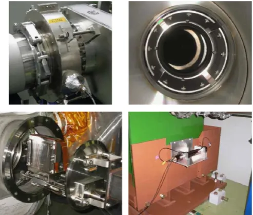
A well-tuned proton beam is essential for stable neutrino beam production, and to minimize beam loss in order to achieve high-power beam operation. Therefore, the intensity, position, profile and loss of the proton beam in the primary sections are precisely monitored by five current transformers (CTs), 21 elec-trostatic monitors (ESMs), 19 segmented secondary emission monitors (SSEMs) and 50 beam loss monitors (BLMs), respec-tively. Photographs of the monitors are shown inFig. 4, while the monitor locations are shown in Fig. 5. Polyimide cables and ceramic feedthroughs are used for the beam monitors, because of their radiation tolerance.
The beam pipe is kept at 3106
Pa using ion pumps, in order to be connected with the beam pipe of the MR and to reduce the heat load to the SCFMs. The downstream end of the beam pipe is connected to the ‘‘monitor stack’’: the 5 m tall vacuum vessel embedded within the 70 cm thick wall between the primary beamline and secondary beamline. The most downstream ESM and SSEM are installed in the monitor stack. Because of the high residual radiation levels, the monitor stack is equipped with a remote-handling system for the monitors.
3.1.1. Normal conducting magnet
The normal conducting magnets are designed to be tolerant of radiation and to be easy to maintain in the high-radiation environ-ment. For the four most upstream magnets in the preparation
Fig. 2.Overview of the T2K neutrino beamline.
Eν (GeV) 0
Flux [/10
21 POT/50 MeV/cm
2]
0 0.2 0.4 0.6 0.8 1 1.2
×106
0.5 1 1.5 2 2.5 3 3.5
Fig. 3.The unoscillatednmflux at Super-Kamiokande with an off-axis angle of 2.51
[image:6.595.305.552.335.544.2]when the electromagnetic horns are operated at 250 kA.
Fig. 4.Photographs of the primary beamline monitors. Upper left: CT. Upper right:
ESM. Lower left: SSEM. Lower right: BLM.
section, a mineral insulation coil is used because of its radiation tolerance. To minimize workers’ exposure to radiation, remote maintenance systems are installed such as twistlock slings, align-ment dowel pins, and quick connectors for cooling pipes and power lines.
For the quadrupole magnets, ‘‘flower-shaped’’ beam pipes, whose surfaces were made in the shape of the magnetic pole surface, are adopted to maximize their apertures.
3.1.2. Superconducting combined function magnet (SCFM)
In total, there are 28 SCFMs[9–12], each with a coil aperture of 173.4 mm. The operating current for a 30 GeV proton beam is 4360 A, while the magnets themselves were tested up to 7500 A, which corresponds to a 50 GeV proton beam.
The combined field is generated with a left–right asymmetric single layer Rutherford-type coil, made of NbTi/Cu. Two SCFMs are enclosed in one cryostat in forward and backward directions to constitute a defocus–focus doublet, while each dipole field is kept in the same direction. All the SCFMs are cooled in series with supercritical helium at 4.5 K and are excited with a power supply (8 kA, 10 V).
There are also three superconducting corrector dipole mag-nets, which are cooled by conduction, in the SCFM section. Each magnet has two windings, one for vertical and one for horizontal deflections. These magnets allow the beam to be precisely positioned along the beamline (to minimize losses).
The magnet safety system (MSS) protects the magnets and the bus-bars of the primary beamline in the case of an abnormal condition, and supplements the passive safety protection pro-vided by cold diodes mounted in parallel with the superconduct-ing magnets. The MSS is based on the detection of a resistive voltage difference across the magnet that would appear in the case of a quench. It then secures the system by shutting down the magnet power supply and issuing a beam abort interlock signal. Most units of the MSS are dual redundant. This redundancy increases the reliability of the system. The MSS is based on 33 MD200 boards[13].
3.1.3. Beam intensity monitor
Beam intensity is measured with five current transformers (CTs). Each CT is a 50-turn toroidal coil around a cylindrical ferromagnetic core. To achieve high-frequency response up to 50 MHz for the short-pulsed bunches and to avoid saturation caused by a large peak current of 200 A, CTs use a FINEMETs (nanocrystalline Fe-based soft magnetic material) core, which has a high saturation flux density, high relative permeability and low core loss over a wide frequency range. The core’s inner diameter is 260 mm, its outer diameter is 340 mm and it has a mass of 7 kg. It is impregnated with epoxy resin. To achieve high radiation hardness, polyimide tape and alumina fiber tape are used to insulate the core and wire. Each CT is covered by an iron shield to block electromagnetic noise.
Each CT’s signal is transferred through about 100 m of 20D colgate cable and read by a 160 MHz Flash ADC (FADC). The CT is calibrated using another coil around the core, to which a pulse current, shaped to emulate the passage of a beam bunch, is applied. The CT measures the absolute proton beam intensity with a 2% uncertainty and the relative intensity with a 0.5% fluctuation. It also measures the beam timing with precision better than 10 ns.
3.1.4. Beam position monitor
Each electrostatic monitor (ESM) has four segmented cylind-rical electrodes surrounding the proton beam orbit (801coverage per electrode). By measuring top–bottom and left–right asymme-try of the beam-induced current on the electrodes, it monitors the
proton beam center position nondestructively (without direct interaction with the beam).
The longitudinal length of an ESM is 125 mm for the 15 ESMs in the preparation and final focusing sections, 210 mm for the five ESMs in the arc section and 160 mm for the ESM in the monitor stack. The signal from each ESM is read by a 160 MHz FADC.
The measurement precision of the beam position is less than 450
m
m (20240m
m for the measurement fluctuation, 1002400m
m for the alignment precision and 200m
m for the systematic uncer-tainty other than the alignment), while the requirement is 500m
m.3.1.5. Beam profile monitor
Each segmented secondary emission monitor (SSEM) has two thin (5
m
m,105interaction lengths) titanium foils stripped horizon-tally and vertically, and an anode HV foil between them. The strips are hit by the proton beam and emit secondary electrons in proportion to the number of protons that go through the strip. The electrons drift along the electric field and induce currents on the strips. The induced signals are transmitted to 65 MHz FADCs through twisted-pair cables. The proton beam profile is reconstructed from the corrected charge distribution on a bunch-by-bunch basis. The strip width of each SSEM ranges from 2 to 5 mm, optimized according to the expected beam size at the installed position. The systematic uncertainty of the beam width measurement is 200
m
m while the requirement is 700m
m. Optics parameters of the proton beam (Twiss parameters and emittance) are reconstructed from the profiles measured by the SSEMs, and are used to estimate the profile center, width and divergence at the target.Since each SSEM causes beam loss (0.005% loss), they are remotely inserted into the beam orbit only during beam tuning, and extracted from the beam orbit during continuous beam operation.
3.1.6. Beam loss monitor
To monitor the beam loss, 19 and 10 BLMs are installed near the beam pipe in the preparation and final focusing sections, respec-tively, while 21 BLMs are positioned near the SCFMs in the arc section. Each BLM (Toshiba Electron Tubes & Devices E6876-400) is a wire proportional counter filled with an Ar–CO2mixture[14].
The signal is integrated during the spill and if it exceeds a threshold, a beam abort interlock signal is fired. The raw signal before integration is read by the FADCs with 30 MHz sampling for the software monitoring.
By comparing the beam loss with and without the SSEMs in the beamline, it was shown that the BLM has a sensitivity down to a 16 mW beam loss. In the commissioning run, it was confirmed that the residual dose and BLM data integrated during the period have good proportionality. This means that the residual dose can be monitored by watching the BLM data.
3.2. Secondary beamline
Produced pions decay in flight inside a single volume of
1500 m3, filled with helium gas (1 atm) to reduce pion absorp-tion and to suppress tritium and NOxproduction by the beam. The helium vessel is connected to the monitor stack via a titanium-alloy beam window which separates the vacuum in the primary beamline and the helium gas volume in the secondary beamline. Protons from the primary beamline are directed to the target via the beam window.
a 250 kA (designed for up to 320 kA) current pulse to focus the pions. The produced pions enter the decay volume and decay mainly into muons and muon neutrinos. All the hadrons, as well as muons below 5 GeV/c, are stopped by the beam dump. The neutrinos pass through the beam dump and are used for physics experiments. Any muons above 5 GeV/cthat also pass through the beam dump are monitored to characterize the neutrino beam.
3.2.1. Target station
The target station consists of the baffle, OTR, target, and horns, all located inside a helium vessel. The target station is separated from the primary beamline by a beam window at the upstream end, and is connected to the decay volume at the downstream end. The helium vessel, which is made of 10 cm thick steel, is 15 m long, 4 m wide and 11 m high. It is evacuated down to 50 Pa before it is filled with helium gas. Water cooling channels, called plate coils, are welded to the surface of the vessel, and 301C water cools the vessel to prevent its thermal deformation. An iron shield with a thickness of 2 m and a concrete shield with a thickness of 1 m are installed above the horns inside the helium vessel. Additionally, 4:5 m thick concrete shields are installed above the helium vessel.
The equipment and shields inside the vessel are removable by remote control in case of maintenance or replacement of the horns or target. Beside the helium vessel, there is a maintenance area where manipulators and a lead-glass window are installed, as well as a depository for radio-activated equipment.
3.2.2. Beam window
The beam window, comprising two helium-cooled 0.3 mm thick titanium-alloy skins, separates the primary proton beamline vacuum from the target station. The beam window assembly is sealed both upstream and downstream by inflatable bellows vacuum seals to enable it to be removed and replaced if necessary.
3.2.3. Baffle
The baffle is located between the beam window and OTR. It is a 1.7 m long, 0.3 m wide and 0.4 m high graphite block, with a beam hole of 30 mm in diameter. The primary proton beam goes through this hole. It is cooled by water cooling pipes.
3.2.4. Optical transition radiation monitor
The OTR has a thin titanium-alloy foil, which is placed at 451to the incident proton beam. As the beam enters and exits the foil,
visible light (transition radiation) is produced in a narrow cone around the beam. The light produced at the entrance transition is reflected at 901to the beam and directed away from the target area. It is transported in a dogleg path through the iron and concrete shielding by four aluminum 901 off-axis parabolic mirrors to an area with lower radiation levels. It is then collected by a charge injection device camera to produce an image of the proton beam profile.
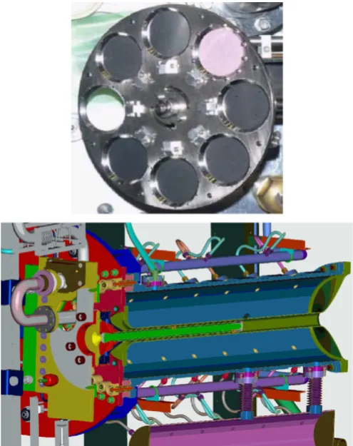
The OTR has an eight-position carousel holding four titanium-alloy foils, an aluminum foil, a fluorescent ceramic foil of 100
m
m thickness, a calibration foil and an empty slot (Fig. 7). A stepping motor is used to rotate the carousel from one foil to the next. The aluminum (higher reflectivity than titanium) and ceramic (which produces fluorescent light with higher intensity than OTR light) foils are used for low and very low intensity beam, respectively. The calibration foil has precisely machined fiducial holes, of which an image can be taken using back-lighting from lasers and filament lights. It is used for monitoring the alignment of the OTR system. The empty slot allows back-lighting of the mirror system to study its transport efficiency.3.2.5. Target
The target core is a 1.9 interaction length (91.4 cm long), 2.6 cm diameter and 1.8 g/cm3 graphite rod. If a material
sig-nificantly denser than graphite were used for the target core, it would be melted by the pulsed beam heat load.
The core and a surrounding 2 mm thick graphite tube are sealed inside a titanium case which is 0.3 mm thick. The target assembly is supported as a cantilever inside the bore of the first horn inner conductor with a positional accuracy of 0.1 mm. The target is cooled by helium gas flowing through the gaps between the core and tube and between the tube and case. For the 750 kW
Fig. 7.Top: Photograph of the OTR carousel. Bottom: Cross section of the first
[image:8.595.303.551.409.722.2]horn and target.
Fig. 6.Side view of the secondary beamline. The length of the decay volume
beam, the flow rate is 32 g/s helium gas with a helium outlet pressure of 0.2 MPa, which corresponds to a flow speed of
250 m/s. When the 750 kW proton beam interacts with the target, the temperature at the center is expected to reach 7001C, using the conservative assumption that radiation damage has reduced the thermal conductivity of the material by a factor of four.
The radiation dose due to the activation of the target is estimated at a few Sv/h six months after a one year’s irradiation by the 750 kW beam[15].
3.2.6. Magnetic horn
The T2K beamline uses three horns. Each magnetic horn consists of two coaxial (inner and outer) conductors which encompass a closed volume[16,17]. A toroidal magnetic field is generated in that volume. The field varies as 1/r, whereris the distance from the horn axis. The first horn collects the pions which are generated at the target installed in its inner conductor. The second and third horns focus the pions. When the horn is run with a operation current of 320 kA, the maximum field is 2.1 T and the neutrino flux at Super-Kamiokande is increased by a factor of 16 (compared to horns at 0 kA) at the spectrum peak energy (0:6 GeV).
The horn conductor is made of aluminum alloy (6061-T6). The horns’ dimensions (minimum inside diameter, inner conductor thickness, outside diameter and length, respectively) are 54 mm, 3 mm, 400 mm and 1.5 m for the first horn, 80 mm, 3 mm, 1000 mm and 2 m for the second horn, and 140 mm, 3 mm, 1400 mm and 2.5 m for the third horn. They are optimized to maximize the neutrino flux; the inside diameter is as small as possible to achieve the maximum magnetic field, and the con-ductor is as thin as possible to minimize pion absorption while still being tolerant of the Lorentz force, created from the 320 kA current and the magnetic field, and the thermal shock from the beam.
The pulse current is applied via a pulse transformer with a turn ratio of 10:1, which is installed beside the helium vessel in the target station. The horns are connected to the secondary side of the pulse transformer in series using aluminum bus-bars. The currents on the bus-bars are monitored by four Rogowski coils per horn with a 200 kHz FADC readout. The measurement uncertainty of the absolute current is less than 2%. The horn magnetic field was measured with a Hall probe before installation, and the uncertainty of the magnetic field strength is approximately 2% for the first horn and less than 1% for the second and third horns.
3.2.7. Decay volume
The decay volume is a 96 m long steel tunnel. The cross section is 1.4 m wide and 1.7 m high at the upstream end, and 3.0 m wide and 5.0 m high at the downstream end. The decay volume is surrounded by 6 m thick reinforced concrete shielding. Along the beam axis, 40 plate coils are welded on the steel wall, whose thickness is 16 mm, to cool the wall and concrete to below 1001C using water.
3.2.8. Beam dump
The beam dump sits at the end of the decay volume. The distance between the center of the target and the upstream surface of the beam dump along the neutrino beam direction for the off-axis angle of 2.51is 109 m. The beam dump’s core is made of 75 tons of graphite (1.7 g/cm3), and is 3.174 m long,
1.94 m wide and 4.69 m high. It is contained in the helium vessel. Fifteen iron plates are placed outside the vessel and two inside, at the downstream end of the graphite core, to give a total iron
thickness of 2.40 m. Only muons above 5:0 GeV/c can go through the beam dump to reach the downstream muon pit.
The core is sandwiched on both sides by aluminum cooling modules which contain water channels. The temperature in the center of the core is kept at around 1501C for the 750 kW beam.
3.3. Muon monitor
The neutrino beam intensity and direction can be monitored on a bunch-by-bunch basis by measuring the distribution profile of muons, because muons are mainly produced along with neutrinos from the pion two-body decay. The neutrino beam direction is determined to be the direction from the target to the center of the muon profile. The muon monitor[18,19] is located just behind the beam dump. The muon monitor is designed to measure the neutrino beam direction with a precision better than 0.25 mrad, which corresponds to a 3 cm precision of the muon profile center. It is also required to monitor the stability of the neutrino beam intensity with a precision better than 3%.
A detector made of nuclear emulsion was installed just down-stream of the muon monitor to measure the absolute flux and momentum distribution of muons.
3.3.1. Characteristics of the muon flux
Based on the beamline simulation package, described in Section 3.5, the intensity of the muon flux at the muon monitor, for 3:31014protons/spill and 320 kA horn current, is estimated to be 1107 charged particles/cm2/bunch with a Gaussian-like
profile around the beam center and approximately 1 m in width. The flux is composed of around 87% muons, with delta-rays making up the remainder.
3.3.2. Muon monitor detectors
The muon monitor consists of two types of detector arrays: ionization chambers at 117.5 m from the target and silicon PIN photodiodes at 118.7 m (Fig. 8). Each array holds 49 sensors at 25 cm25 cm intervals and covers a 150150 cm2 area. The
collected charge on each sensor is read out by a 65 MHz FADC. The 2D muon profile is reconstructed in each array from the distribution of the observed charge.
[image:9.595.314.561.526.713.2]The arrays are fixed on a support enclosure for thermal insulation. The temperature inside the enclosure is kept at around 341C (within 70:71C variation) with a sheathed heater, as the
Fig. 8. Photograph of the muon monitor inside the support enclosure. The silicon
signal gain in the ionization chamber is dependent on the gas temperature.
An absorbed dose at the muon monitor is estimated to be about 100 kGy for a 100-day operation at 750 kW. Therefore, every component in the muon pit is made of radiation-tolerant and low-activation material such as polyimide, ceramic, or aluminum.
3.3.3. Ionization chamber
There are seven ionization chambers, each of which contains seven sensors in a 150501956 mm3aluminum gas tube. The
75753 mm3 active volume of each sensor is made by two
parallel plate electrodes on alumina-ceramic plates. Between the electrodes, 200 V is applied.
Two kinds of gas are used for the ionization chambers accord-ing to the beam intensity: Ar with 2% N2for low intensity, and
He with 1% N2 for high-intensity. The gas is fed in at
approxi-mately 100 cm3/min. The gas temperature, pressure and oxygen contamination are kept at around 341C with a 1.51C gradient and
70.21C variation, at 13070.2 kPa (absolute), and below 2 ppm, respectively.
3.3.4. Silicon PIN photodiode
Each silicon PIN photodiode (HamamatsusS3590-08) has an active area of 1010 mm2 and a depletion layer thickness of
300
m
m. To fully deplete the silicon layer, 80 V is applied. The intrinsic resolution of the muon monitor is less than 0.1% for the intensity and less than 0.3 cm for the profile center.3.3.5. Emulsion tracker
The emulsion trackers are composed of two types of modules. The module for the flux measurement consists of eight consecu-tive emulsion films [20]. It measures the muon flux with a systematic uncertainty of 2%. The other module for the momen-tum measurement is made of 25 emulsion films interleaved by 1 mm lead plates, which can measure the momentum of each particle by multiple Coulomb scattering with a precision of 28% at a muon energy of 2 GeV/c[21,22]. These films are analyzed by scanning microscopes[23,24].
3.4. Beamline online system
For the stable and safe operation of the beamline, the online system collects information on the beamline equipment and the beam measured by the beam monitors, and feeds it back to the operators. It also provides Super-Kamiokande with the spill information for event synchronization by means of GPS, which is described in detail in Section 3.6.2.
3.4.1. DAQ system
The signals from each beam monitor are brought to one of five front-end stations in different buildings beside the beamline. The SSEM, BLM, and horn current signals are digitized by a 65 MHz FADC in the COPPER system [25]. The CT and ESM signals are digitized by a 160 MHz VME FADC[26]. The GPS for the event synchronization and the OTR both use custom-made readout electronics. All of these readout systems are managed by the MIDAS framework [27], and the event builder records fully concatenated events every spill, before the next spill is issued. MIDAS’s event monitoring system locks the internal data holding buffer. To minimize the locking time, which can have a negative effect on the DAQ system’s response time, an event distributor was developed. It receives event data from the MIDAS server and distributes the data in ROOT format to the clients. No reduction is
applied to the output from the ADCs and the event data size remains constant at 1.6 MB.
3.4.2. Beamline control system
Information on the beamline (the beam monitor outputs, spill number and status of the beamline equipment) is recorded by EPICS [28]. EPICS also controls the beamline equipment using programmable logic controllers (PLCs).
Based on the data from EPICS, the beam orbit and optics are simulated by SAD[29], and the magnet currents to be adjusted are also calculated.
3.4.3. Interlock
The function of the interlock system is to protect people (PPS: person protection system) and the machines (MPS: machine protection system). The PPS can be fired by an emergency stop button, or safety sensors such as door interlocks and radiation monitors. The MPS can be fired by a quenching of the SCFMs, an error from the normal conducting magnet or horn system, an excess in the loss monitor signal, or other machine-related causes.
3.5. Beamline simulation for neutrino flux estimation
The neutrino flux is predicted by a Monte Carlo simulation based on experimental data. Specifically, hadron production by 30 GeV protons on a graphite target was measured by a dedicated experiment, NA61/SHINE [30,31], which fully covers the kine-matic region of interest for T2K.
In the beam MC, the detailed geometry of the secondary beam-line is described in the code. Protons with a kinetic energy of 30 GeV are injected into the graphite target and then secondary particles are produced and focused in the horn magnets. The secondaries and any un-interacted protons are tracked until they decay into neutrinos or are stopped at the beam dump. The tracks of neutrinos are extrapolated to the near and far detectors, provid-ing the predicted fluxes and energy spectra at both detector sites.
The primary interaction of the 30 GeV proton with carbon is simulated based on NA61/SHINE data. Other hadronic interac-tions inside the target are simulated by FLUKA[32]. The interac-tions outside the target are simulated using GEANT3/GCALOR[33]
with the interaction cross sections tuned to experimental data.
3.6. Global alignment and time synchronization
3.6.1. Global position survey and alignment
In a long baseline neutrino experiment, controlling the direc-tion of the neutrino beam is one of the most important aspects. For the T2K neutrino experiment, it is necessary to consider the three-dimensional geometry of the earth, since it covers a distance of 300 km from J-PARC to Super-Kamiokande. Deter-mining the correct direction is not simple. Therefore, surveys were performed, including a long baseline GPS survey between Tokai and Kamioka.
Based on the surveys, the primary beamline components, target, and horns were aligned in order to send the neutrino beam in the right direction. The muon monitor and the neutrino near detectors were also aligned in order to monitor the neutrino beam direction. A good alignment of the components is also necessary in order to reduce irradiation in a high-intensity proton beamline.
can be monitored even after the underground helium vessel is closed. In the primary beamline, a survey and alignment is carried out using a laser tracker with a spatial resolution of 50
m
m at a distance shorter than 20 m. The superconducting magnets were aligned to better than 100m
m and the normal conducting quad-rupole magnets were aligned to better than 1 mm. In the other places, a survey is carried out using a total station which gives a spatial resolution of about 2 mm at a distance of 100 m.We observed a ground sink of a few tens of millimeters during the construction stage. It was taken into account at the installa-tion of the beamline components. After the installainstalla-tion at the primary beamline, we still observed a sink of several millimeters at the final focusing section and the target station. Therefore, the beam was tuned to follow the beamline sink.
The required directional accuracy from the physics point of view is 1103
rad. The directional accuracy of a long baseline GPS survey is several times 106rad. That of a short distance survey is a few times 105
rad. It was confirmed by surveys after construction that a directional accuracy of significantly better than 1104rad was attained.
The measured distance between the target and the center position of Super-Kamiokande is 295,335:270:7 m. The mea-sured off-axis angle is 2:50470:0041.
3.6.2. Time synchronization
The T2K GPS time synchronization system builds on experi-ence from K2K, taking advantage of subsequent advances in commercially available clock systems and related technology. The system provides O(50 ns) scale synchronization between neutrino event trigger timestamps at Super-Kamiokande, and beam spill timestamps logged at J-PARC.
The heart of the system is a custom electronics board called the local time clock (LTC). This board uses a time base derived from a commercial rubidium clock, and references it to GPS time using input from two independent commercial GPS receivers. The operational firmware was coded to interface efficiently with the Super-Kamiokande or J-PARC data acquisition systems.
The LTC receives 1 pps (pulse per second) signals from two independent GPS receivers. These signals have their leading edges aligned with the second transitions in UTC to higher precision than required for T2K. The primary receiver is a TrueTime (Symmetricom) rack-mounted receiver, and the secondary receiver is a Synergy Systems SynPaQIII receiver, mounted as a daughtercard on the LTC itself. The receivers are connected to antenna modules located with a clear view of the sky, near the mine entrance at Super-Kamio-kande, and at J-PARC. The Rb clock which provides a stabilized time base for the system in case of temporary loss of GPS signals is a Stanford Research Systems model FS-725. The LTC is interfaced to the data acquisition system through a Linux PC with fast network connections. At J-PARC, an independent optical fiber link sends data directly to the ND280 data acquisition system.
When the timing signal, synchronized with the MR extraction, is received its time is recorded to an LTC module at J-PARC. The LTC module counts the accumulated number of received signals as the spill number. This time information and the spill number are sent to Super-Kamiokande through a private network, and are returned from Super-Kamiokande to check consistency. The LTC module also provides the beam trigger for the beam monitors.
At each site, two independent GPS systems run in parallel at all times to eliminate downtime during T2K running.
4. Near detector complex (ND280)
As stated earlier, the T2K experiment studies oscillations of an off-axis muon neutrino beam between the J-PARC accelerator
complex and the Super-Kamiokande detector, with special emphasis on measuring the unknown mixing angle
y
13by obser-ving the subdominantn
m-n
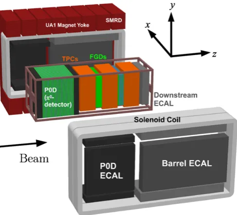
e oscillation. The neutrino energy spectrum, flavor content, and interaction rates of the unoscillated beam are measured by a set of detectors located 280 m from the production target, and are used to predict the neutrino interac-tions at Super-Kamiokande.The primary detector at the 280 m site is a magnetized off-axis tracking detector. The off-axis detector elements are contained inside the magnet recycled from the UA1 experiment at CERN. Inside the upstream end of this magnet sits a pi-zero detector (PØD) consisting of tracking planes of scintillating bars alternat-ing with either water target/brass foil or lead foil. Downstream of the PØD, the tracker, comprising three time projection chambers (TPCs) and two fine grained detectors (FGDs) consisting of layers of finely segmented scintillating bars, is designed to measure charged current interactions in the FGDs. The PØD, TPCs, and FGDs are all surrounded by an electromagnetic calorimeter (ECal) for detecting
g
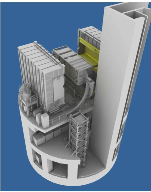
-rays that do not convert in the inner detectors, while the return yoke of the magnet is instrumented with scintillator to measure the ranges of muons that exit the sides of the off-axis detector. In addition to the off-axis detector, a separate array of iron/scintillator detectors called INGRID mea-sures the on-axis neutrino beam profile at the 280 m site, while a set of muon monitor detectors located downstream of the beam dump monitors the beam direction and profile by detecting high energy muons from pion decay, as described earlier in Section 3.3. All detectors use the same coordinate convention:zis along the nominal neutrino beam axis, and x and y are horizontal and vertical, respectively.These detectors are housed in a pit inside the ND280 hall (seeFig. 9). The pit has a diameter of 17.5 m and a depth of 37 m, and has three floors. The B1 floor, about 24 m below the surface, houses the off-axis detector, which is located on the line between the target point and the Super-Kamiokande position. The Service Stage, about 33 m deep, houses the horizontal modules of the INGRID detector. It also holds the electronics and many of the services for the off-axis detectors. The B2 floor, about 37 m deep, houses the bottom modules of the vertical INGRID detector. The current off-axis angle is 2.51, which has the extrapolated on-axis beam passing at about 1 m above the Service Stage. This facility design can accommodate off-axis angles in the range of between 2.0 and 2.51, constrained by the requirement that the beam axis pass through the central area of the on-axis detector. Outside of this area, the measurement of the beam axis direction would deteriorate. A building with an internal area of 21 m28 m covers the pit, and has a 10 ton crane.
4.1. Multi-pixel photon counter (MPPC)
of operation of multi-pixel photodiodes can be found in a recent review paper[34]and the references therein.
After R&D and tests provided by several groups for three years, the Hamamatsu Multi-Pixel Photon Counter (MPPC) was chosen as the photosensor for ND280. The MPPC gain is determined by the charge accumulated in a pixel capacitance Cpixel: Qpixel¼
Cpixel
D
V, where the overvoltageD
V is the difference betweenthe applied voltage and the breakdown voltage of the photodiode. For MPPCs the operational voltage is about 70 V, which is 0.8–1.5 V above the breakdown voltage. The pixel capacitance is 90 fF, which gives a gain in the range 0.5–1.5106. When a
photoelectron is produced it creates a Geiger avalanche. The amplitude of a single pixel signal does not depend on the number of carriers created in this pixel. Thus, the photodiode signal is a sum of fired pixels. Each pixel operates as a binary device, but the multi-pixel photodiode as a whole unit is an analog detector with a dynamic range limited by the finite number of pixels.
A customized 667-pixel MPPC, with a sensitive area of 1.31.3 mm2, was developed for T2K [35,36]. It is based on a
Hamamatsu commercial device, the sensitive area of which was increased to provide better acceptance for light detection from 1 mm diameter Y11 Kuraray fibers. In total, about 64,000 MPPCs were produced for T2K. The T2K photosensor is shown inFig. 10. The main parameters of MPPCs are summarized inTable 2. The characterization of the MPPCs’ response to scintillation light is presented in Ref.[37].
4.2. INGRID on-axis detector
INGRID (Interactive Neutrino GRID) is a neutrino detector centered on the neutrino beam axis. This on-axis detector was
designed to monitor directly the neutrino beam direction and intensity by means of neutrino interactions in iron, with sufficient statistics to provide daily measurements at nominal beam inten-sity. Using the number of observed neutrino events in each module, the beam center is measured to a precision better than 10 cm. This corresponds to 0.4 mrad precision at the near detector pit, 280 m downstream from the beam origin. The INGRID detector consists of 14 identical modules arranged as a cross of two identical groups along the horizontal and vertical axis, and two additional separate modules located at off-axis directions outside the main cross, as shown inFig. 11. The detector samples the neutrino beam in a transverse section of 10 m10 m. The center of the INGRID cross, with two overlapping modules, corresponds to the neutrino beam center, defined as 01 with respect to the direction of the primary proton beamline. The purpose of the two off-axis modules is to check the axial symmetry of the neutrino beam. The entire 16 modules are installed in the near detector pit with a positioning accuracy of 2 mm in directions perpendicular to the neutrino beam.
[image:12.595.34.282.55.369.2]The INGRID modules consist of a sandwich structure of nine iron plates and 11 tracking scintillator planes as shown inFig. 12. They are surrounded by veto scintillator planes, to reject interactions
Fig. 9.ND280 detector complex. The off-axis detector and the magnet are located
[image:12.595.304.548.59.153.2]on the upper level; horizontal INGRID modules are located on the level below; and the vertical INGRID modules span the bottom two levels.
Fig. 10.Photographs of an MPPC with a sensitive area of 1.31.3 mm2: magnified
[image:12.595.302.545.223.499.2]face view (left) with 667 pixels in a 2626 array (a 9-pixel square in the corner is occupied by an electrode); the ceramic package of this MPPC (right).
Table 2
Main parameters of the T2K MPPCs.
Number of pixels 667
Active area 1.31.3 mm2
Pixel size 5050mm2
Operational voltage 68–71 V
Gain 106
Photon detection efficiency at 525 nm 26–30% Dark rate, threshold¼0.5 p.e.,T¼251C r1:35 MHz
[image:12.595.306.551.229.299.2]outside the module. The dimensions of the iron plates are 124 cm
124 cm in the x and y directions and 6.5 cm along the beam direction. The total iron mass serving as a neutrino target is 7.1 tons per module. Each of the 11 tracking planes consists of 24 scintillator bars in the horizontal direction glued to 24 perpendicular bars in the vertical direction with Cemedine PM200, for a total number of 8448. No iron plate was placed between the 10th and 11th tracking planes due to weight restrictions, but this does not affect the tracking performance. The dimensions of the scintillator bars used for the tracking planes are 1.0 cm5.0 cm120.3 cm. Due to the fact that adjacent modules can share one veto plane in the boundary region, the modules have either three or four veto planes. Each veto plane consists of 22 scintillator bars segmented in the beam direction. The dimensions of those scintillator bars are 1.0 cm5.0 cm111.9 cm (bottom sides) and 1.0 cm5.0 cm
129.9 cm (top, right and left sides). The total number of channels for the veto planes is 1144, which gives a total of 9592 channels for INGRID as a whole.
The extruded scintillator bars used for the tracking and veto planes are made of polystyrene doped with 1% PPO and 0.03% POPOP by weight. The wavelength of the scintillation light at the emission peak is 420 nm (blue). They were developed and produced at Fermilab [38]. A thin white reflective coating, composed of TiO2 infused in polystyrene, surrounds the whole
of each scintillator bar. The coating improves light collection efficiency by acting as an optical isolator. A hole with a diameter of about 3 mm in the center of the scintillator bar allows the insertion of a WLS fiber for light collection.
The WLS fibers used for INGRID are 1 mm diameter Kuraray double-clad Y-11. The absorption spectrum of the fiber is centered at a wavelength of 430 nm (blue). The emission spectrum is centered at 476 nm (green), and the overlap between the two is small, reducing self-absorption effects in the fiber. One end of the fiber is glued to a connector by epoxy resin (ELJEN Technology EJ-500). The surface of the connector was polished with diamond blades. An MPPC is attached to each fiber using the connector. A detailed description of the MPPCs can be found in Section 4.1. Some characterization of the MPPCs used for INGRID can be found in Refs.[36,39].
Finally, the set of scintillators, fibers and photosensors is contained in a light-tight dark box made of aluminum frames and plastic plates. The readout front-end electronics boards, the Trip-T front-end boards (TFBs), are mounted outside the dark box and each connected to 48 MPPCs via coaxial cables. This forms one complete tracking scintillator plane.
INGRID was calibrated using cosmic ray data taken on the surface and, during beam, in the ND280 pit. The mean light yield of each channel is measured to be larger than 10 photoelectrons per 1 cm of MIP tracks which satisfies our requirement.
Furthermore, the timing resolution of each channel is measured to be 3.2 ns.
An extra module, called the Proton Module, different from the 16 standard modules, has been added in order to detect with good efficiency the muons together with the protons produced by the neutrino beam in INGRID. The goal of this Proton Module is to identify the quasi-elastic channel for comparison with Monte Carlo simulations of beamline and neutrino interactions. It con-sists of scintillator planes without any iron plate and surrounded by veto planes. A different size scintillator bar was used to improve tracking capabilities. A schematic view of the Proton Module can be seen inFig. 13. It is placed in the pit in the center of the INGRID cross between the standard vertical and horizontal central modules.
Typical neutrino events in the INGRID module and the Proton Module are shown inFigs. 14 and 15.
4.3. Off-axis detector
[image:13.595.47.291.66.184.2]A large fine grained off-axis detector (see Fig. 16) serves to measure the flux, energy spectrum and electron neutrino contam-ination in the direction of the far detector, along with measuring rates for exclusive neutrino reactions. This characterizes signals and backgrounds in the Super-Kamiokande detector.
Fig. 12.An INGRID module. The left image shows the tracking planes (blue) and
[image:13.595.358.515.331.481.2]iron plates. The right image shows veto planes (black). (For interpretation of the references to color in this figure legend, the reader is referred to the web version of this article.)
Fig. 13.The Proton Module. Similar to the INGRID modules, but with finer grain
scintillator and without the iron plates.
Fig. 14.A typical neutrino event in an INGRID module. A neutrino enters from the
[image:13.595.314.561.519.682.2]