LECTURE NOTES <FACULTY>
<TITLE>
<Auteur>
<NR>
<MAAND JAAR> COURSE ID: <ID> PRINTS: <#> PRICE: € 0,00
Design of vacuum
components for
FERP-technique
characterization
system
INTERNSHIP REPORT MECHANICAL ENGINEERING
DESIGN ENGINEERING
Gerben Groeneveld
s1013823
1
Design of vacuum components for FERP-technique characterization system
Internship report Master Mechanical Engineering
Gerben Groeneveld s1013823
CTI Renato Archer
Rodovia Dom Pedro I (SP-65), Km 143,6 – Amarais, Campinas – SP, CEP 13069-901, Brazil
Surface Interaction & Display Division, DMI
Campinas, state of São Paulo, Brazil 06-01-2016 to 06-04-2016
Vinicius L. Pimentel dr. ir. Wessel W. Wits
60 4
08-08-2016
University of Twente
Faculty of Engineering Technology
Design, Production and Management – Design Engineering De Horst (building 20), room N204
Postbus 217 7500 AE Enschede The Netherlands Student:
Student number:
Company name & address:
Division:
Internship location: Internship period:
Mentor CTI:
Supervisor University of Twente:
Report pages (excl. appendices): Appendices:
2
Preface
This document describes the findings of an internship carried out be me at the Center of
Information Technology (CTI) in Campinas-SP, Brazil. This internship lasted from the January to the start of April 2016 and is part of the Master Mechanical Engineering from the University of
Twente, Enschede, the Netherlands.
I traded the cold winter in the Netherlands for a burning Brazilian summer and ended up in a culture of samba, churrascu and caipirinhas. On these hot summer days, the air-conditioning in the laboratory of DMI was a welcome treat. Here it was, that I spent my time on a vacuum study and contributed to the future FERP-research system, as described in this report. I want to thank Vinicius, Mamoru and all the other colleagues at DMI for their helpful knowledge, constructive support throughout the project, but also the fun we had together. I had a wonderful time in Brazil with a lot of new experiences, cultural and technical. The Brazilians made me feel very welcome, which makes that I am wistfully watching the Olympic Games of Rio 2016.
This document is the result of the technical experiences that I had in Campinas. To the reader: I hope this report may be interesting to read and contain well-explained information.
Groningen, the Netherlands August 2016
Gerben Groeneveld
Me and internship supervisor Vinicius L. Pimentel with brand-new vacuum equipment in the laboratory of DMI.
3
Abstract
In the laboratory of DMI, the display division of CTI, research is carried out to find out the work function of materials using the FERP-method. For this method is an ultra-high vacuum (UHV) environment needed. The laboratory of DMI currently has a FERP-setup that is specified for high vacuum (HV). This setup functioned as a ‘proof of principle’, in order to show that the laboratory is able to carry out this kind of research. With the successful outcome of earlier FERP-experiments, the research can now be improved. A concept is created for an UHV-system that enables more accurate results. With the new system, DMI wants to achieve the pressure level of 5x10-12 Torr (for readability pressure levels are presented in this format).
A CAD-model of the new UHV-concept is used by DMI to acquire budget for the required commercial components. In early 2016, all commercial components are arrived and need to be connected by specified nipples. The existing CAD-model featured these connections, but not yet dimensioned and detailed for manufacturing. These detailed designs are provided within this internship. First, a study into vacuum principles and equipment is carried to be able to describe the complete FERP-system accurately. Here it is described that vacuum is the state of a gas with a pressure level below the atmospheric pressure. In vacuum technology, there are different regimes distinguished, based on a difference in molecular behavior. HV and UHV are the two regimes with the lowest pressures, below 1x10⁻⁶ Torr. The difference between vacuum regimes implies the use of different pumping- and measurement principles. This means that a range of pumps and gauges needs to be used to reach the desired UHV-level. Besides this, different commercial components as gate valves, a TSP-Cryoshroud, spheres and a transfer arm are used in the setup.
4
Table of contents
1
Introduction ... 6
1.1 Assignment ... 6
1.2 Company and division – CTI and DMI ... 7
1.3 Report build-up ... 9
2
Theory ... 10
2.1 FERP ... 10
2.2 Theory of vacuum... 11
2.2.1 Definition of vacuum ... 11
2.2.2 Vacuum regimes ... 12
3
Equipment ... 15
3.1 Vacuum pumps ... 15
3.1.1 Diaphragm pump ... 16
3.1.2 Turbo-molecular pump ... 16
3.1.3 Ion pump ... 17
3.1.4 Other types of pumps... 18
3.1.5 Pump sequence ... 19
3.2 Vacuum gauges ... 20
3.2.1 Pirani - thermocouple gauge ... 20
3.2.2 Penning gauge ... 21
3.2.3 Ion gauge ... 21
3.3 Vacuum flanges ... 22
3.3.1 KF Flanges ... 23
3.3.2 CF Flanges ... 23
3.3.3 Sizes and versions of CF-flange ... 24
3.4 Other equipment ... 25
3.4.1 Spheres ... 25
5
3.4.3 Gate valves ... 26
3.4.4 Transfer arm ... 26
3.4.5 Residual Gas Analyzer ... 27
3.4.6 TSP Cyroshroud ... 27
3.5 Outgassing and bake-out ... 28
4
Design ... 29
4.1 From quick concept to final design ... 29
4.2 Requirements ... 30
4.3 Crossing ... 31
4.3.1 New crossing design ... 32
4.3.2 Crossing part dimensions and production ... 34
4.4 Nipples ... 37
4.4.1 Nipple between main chamber and crossing ... 38
4.4.2 Nipples between small sphere and main chamber ... 39
4.4.3 Nipples between small sphere and turbo-molecular pump ... 46
4.5 Top flange for main chamber ... 48
5
Assembly ... 49
5.1 CAD-model of complete setup ... 49
5.2 Procedure before FERP-experiment ... 50
5.3 System weight and support structure ... 51
5.3.1 List of system components and weight ... 51
5.3.2 Support structure ... 51
6
Conclusion & recommendations ... 55
7
Reflection on the internship... 56
References ... 58
Appendix A – Pump pressures ... 61
Appendix B – RGA spectrum ... 62
Appendix C – Standardized tube sizes ... 63
6
1 Introduction
With a new research setup in the laboratory of DMI, the FERP-method will be applied to retrieve work functions of materials. A vacuum environment is needed for this method. The research setup is not yet completed. This report describes the findings of an internship, in which a study is done to the required vacuum components of the new setup. Designs are made for required connections between commercial components and in the end a complete CAD-model of the new setup is provided. This sections introduces the assignment motive, company and division in more detail.
1.1 Assignment
This internship assignment starts, where another assignment ended. The previous assignment was carried out at CTI in 2014 by University of Twente student Jildert Anema. He contributed to the development of an initial setup for work function research by the FERP technique. He designed and combined the models of the required vacuum components. The end product was a complete CAD-model of this system, that was specified for high vacuum pressures (HV).
After this, a new ‘dream’ system was designed. A CAD-model of this setup was used to obtain budget for this project from CTI management. With approval for the project, the received budget was used to purchase required commercial components. In theory, this new system enables FERP-research at operating pressures of about 5x10-12 Torr, in the ultra-high vacuum regime (UHV). Figure 1.1 shows the high vacuum FERP-system and the new UHV-concept.
Figure 1.1 – HV-system in DMI laboratory (left) and CAD-model of new UHV-concept (right) (1)
7
work functions will be more accurate. Secondly, DMI wants to extend the possibilities of the laboratory. The new UHV-setup could for instance be used for electron microscopy applications.
Here starts this internship assignment:
The existing CAD-model of the UHV-concept only functioned to receive budget for commercial components. This model was a quickly built, why no detail was spent to the design of the
connections, called nipples in vacuum technology. To be able to build the new concept, these parts need to be detailed within the physical constraints of the system. This report describes the design and development of these parts. In the end, the commercial components and designed parts are combined in a new detailed CAD-model of the complete research setup. Again, the final model is used to request budget for manufacturing.
The desired level of detail consists of technical drawings to be used for manufacturing. The nipples need to be designed specifically for this setup. They cannot be purchased as the other commercial parts. Manufacturing is done at either the CTI workshop or an external manufacturer.
The goal of this assignment as formulated by internship supervisor Vinicius L. Pimentel was to detail the components to be machined in the CTI workshop and track their manufacturing. Due to budget constraints however, manufacturing is not carried out during the internship period. The designs made is this report now have the function to obtain required budget as soon as possible, in order for the FERP-system to be completed.
The goals of this internship can be summarized as follows:
1. Design of new parts and inclusion of commercial components in research setup up to:
- Precise presentation (CAD) of complete new setup to acquire budget
- Detailed technical drawings of designs to be used for manufacturing
2. Carry out a study about vacuum technology, principles and equipment
1.2 Company and division – CTI and DMI
This internship is carried out at the company CTI, or Centro de Tecnologia da Informação Renato Archer. Translated: Center of Information Technology “Renato Archer”. CTI is located in Campinas in the state of São Paulo, Brazil. It is a research unit of the Ministry of Science, Technology and Innovation (MCTI), and therefore a government funded institution. Research focuses on IT, micro-electronics, displays, software and automation. The goal is to develop new innovations and technologies. This way, CTI provides a link between the academia and technological industry in Brazil (2).
8
Informação, the Surface Interaction and Display Division. DMI’s research concerns for instance the development new types of displays, solar cells and organic electronics. The FERP-system of this project focuses on obtaining the work function of materials, which is a useful property in display manufacturing. This report often refers to ‘DMI’, as it is the most important actor. Figure 1.2 shows the laboratory of DMI where the FERP-research takes place, the workplace of internship supervisor Vinicius L. Pimentel. Other DMI laboratories are mostly designed for chemical research purposes.
Figure 1.2 – DMI laboratory where FERP-system is located
Budget cuts at CTI
In the current economic crisis in Brazil in early 2016, budget cuts are frequent and there are only few possibilities for expenses by CTI. To illustrate this: in the last quarter of 2015, the CTI board was forced to economize by closing the company restaurant and removing the option for a free private bus towards the premises for employees without cars. This affects for instance the travel of student employees from university UNICAMP and foreign interns like the ones from the University of Twente.
9
The economic and political crisis in Brazil affects everyone in the country, but a government funded company as CTI may suffer even more. It was unfortunate to get to know that some colleagues at the DMI division had to leave the company in the last part of 2015.
1.3 Report build-up
This first chapter provided the introduction. The next chapter focuses on the theory: the FERP-research is shortly discussed and the principles of vacuum are explained. Chapter 3 focuses on the commercial vacuum components and their working principles, part of the study into vacuum. In chapter 4 the designs to complete the setup are proposed. Chapter 5 describes the combination of the commercial components and new designs into a complete CAD-model of the new
10
2 Theory
2.1 FERP
The purpose of the future vacuum research setup in the laboratory of DMI, is to function for FERP-research and electron microscopy. Although it is not the objective of this project to understand the physical underlying principles of these methods, it is useful to get some insight in the type of research carried out. For the completeness of the report, the FERP method is shortly discussed.
FERP is short for Field Emission Retarding Potential. It is a method used to obtain the work function of material. A FERP-setup consists of a triode, featuring a cathode (emitter), gate and anode (collector) (3). Figure 2.1 shows a model in which the cathode is indicated as CNT.
Figure 2.1 – elements of FERP-setup (3)
FERP can be split in Field Emission (FE) and Retarding Potential (RP). The first part is Field Emission. To this end, a single atom tip cathode is used. By applying a high voltage (500V) on the grid (first disk), electrons are released from the tip. The second disk is grounded, which ´brakes´ the electrons. This second disk features a smaller aluminum disk with a gap to let only electrons pass with a path perpendicular to the surface of the sample. The use of a magnet in the first disk helps to focus the electron paths on the collector. A cloud of electrons is formed. They cannot reach the anode unless a forward potential is applied. This is the second part: Retarding Potential.
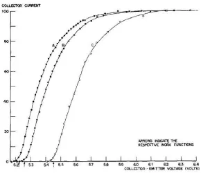
To this end, the voltage over the sample or collector is increased. The floating electrons only jump towards the sample if the voltage is high enough to attract them. Once this happens, a peak is observed in the grid current, measured by an Ampere meter. This peak represents the work function of the sample material.
11
Figure 2.2 – obtained work functions for different sample materials (4)
A high to ultra-high vacuum is required for the FERP research. The path of the electrons must be free of any other molecules, which interfere. In the UHV-concept, the FERP-head is placed on top of the main chamber (the large sphere in Figure 1.1). This head contains the electron tip, the grid, the collector etc. as seen in Figure 2.1. A plate with the sample material for which the work function is determined must be placed in the collector location. This sample is introduced using a transfer arm. This procedure is discussed later on in this report.
For a detailed description of the FERP-method and its underlying principles of quantum physics, the reader is advised to consult dedicated literature (3, 5).
2.2 Theory of vacuum
It is mentioned that a vacuum is needed for the FERP-research. The theory of vacuum forms the basis for how the new research setup is built and needs to function. It is essential to understand the principles of vacuum, to be able to understand what happens in the system to be designed.
2.2.1 Definition of vacuum
Thorough understanding of vacuum starts with knowing the scientific description. Different
sources of literatureprovide a slightly different approach, but are in essence the same. A gas is
12
Everest. In the foregoing project carried out by Jildert Anema (1), the first approach is taken. The following definition of vacuum is also given here:
Vacuum describes the state of a gas in a chamber, of which its pressure is lower than the pressure in the surrounding space. In this project a gas is said to be in vacuum when its pressure is below 750 Torr.
Just below the 750 Torr boundary of vacuum, a gas is said to be in rough vacuum. Process pressures used in industrial applications of vacuum are mostly in the order of 7.5x10⁻³ Torr to 7.5x10⁻⁵ Torr (8), which is in medium to high vacuum. The ultra-high vacuum pressure desired for the new setup at DMI is very much lower: 5x10-12 Torr. A distinction between these vacuum regimes is made, because of the difference in molecular behavior seen at the reduction of pressure.
Note that gas pressure can be given in many different units. The atmospheric pressure at sea level is for instance 1 atm ≈ 100,000 Pa ≈ 1000 mbar ≈ 750 Torr. The standard unit used in
documentation of DMI is Torr, according to the American unit system. This unit is therefore used in the continuation of this report.
2.2.2 Vacuum regimes
The difference in vacuum regimes is based on the amount of gas particles still present in a system. The molecular behavior in a rough vacuum, just below the 750 Torr level, is completely different from the behavior of the leftover gas particles in the higher vacuum levels. This makes obtaining and maintaining a vacuum a challenging process.
To categorize the molecular behavior, a total of 4 different vacuum regimes are distinguished. The corresponding pressure ranges are given in Table 2.1. The boundary of each region cannot be rigidly defined, but these terms are useful when discussing the actions of molecules inside the vacuum system (6).
Vacuum stage Pressure range
Rough Vacuum 760 Torr to 75 milliTorr
Medium (Process) Vacuum 75 milliTorr to 1x10⁻⁶ Torr
High Vacuum 1x10⁻⁶ Torr to 1x10⁻⁹ Torr
Ultra-high Vacuum below 1x10⁻⁹ Torr
Table 2.1 – pressure ranges of vacuum regimes (8)
13
Rough Vacuum
[image:14.612.134.482.186.423.2]The first stage of vacuum is a rough vacuum, with pressures just below the atmospheric pressure. There are still lots of gas particles present in a vacuum chamber, interacting with each other following the laws of thermodynamics (8). This regime is characterized by viscous flow, which is graphically represented in Figure 2.3a. The fluid flow pumps used to obtain these vacuum levels, function to remove the bulk material from the vacuum chamber. These are the type of pumps well known to mechanical engineers, that is why they are often referred to as mechanical pumps.
Figure 2.3 – viscous and molecular flow (8)
Medium Vacuum
The second regime is called medium vacuum, present in many industrial applications of vacuum (8). Pressures are in the range of 75 milliTorr to 1x10⁻⁶ Torr. The flow regime in this vacuum stage is called transition flow. This is a very complex regime between the viscous and the molecular flow, which is seen in even lower pressures. With the use of specified vacuum pumps, the transition from viscous flow to molecular flow is often short. The molecular behavior in this transition cannot be described accurately, because there is a random factor present.
In case of a medium vacuum in industrial processes, often a high vacuum is created first. After that a gas is injected which increases the pressure again towards a medium vacuum. This gas is added for the purpose of the process or experiment.
High Vacuum (HV)
14
The molecular flow features far more molecule-chamber wall collisions than molecule-molecule collisions, because the chamber dimensions are far greater than the mean free path of the leftover molecules (8). This means that another pumping principle needs to be applied. High vacuum pumps are statistical pumps; they do not suck the molecules out of the chamber, but rather wait until a molecule reaches the pump to be removed from the chamber. High vacuum pumps are not appropriate for higher pressure gasses and cannot be exposed to atmosphere. These type of pumps must therefore be backed by mechanical pumps. A combination of mechanical and high vacuum pumps must be applied to obtain and maintain a high vacuum.
Ultra-high vacuum (UHV)
Ultra-high vacuum is the ultimate regime described in vacuum science, covering the lowest pressures. This is the desired regime for the future research setup at DMI. High vacuum and ultra-high vacuum are both dominated by the molecular flow, but in UHV more residual gasses have been removed from the chamber. To reach the pressures below 1x10⁻⁹ Torr, focus lies on removing the gas load from the chamber walls. This gas load can be recognized in Figure 2.3b. Furthermore, the dominant molecule in high vacuum is usually water, while UHV is almost 100% dry and contains hydrogen as the most prevalent residual gas. Hydrogen is light and mobile and very difficult to pump (8). To remove water and gas load from the walls, additional equipment is used. For instance, a TSP or Titanium Sublimation Pump, explained in section 3.4.6. Also
procedures like a bake-out are required, see section 3.5.
15
3 Equipment
The future setup at DMI will be built from equipment that is already present in the laboratory. Parts from the current setup and newly purchased parts are combined into a larger configuration that is appropriate for UHV research. This chapter elaborates on the required equipment and explains working principles and properties. Vacuum pumps, gauges, flanges and other equipment are reviewed. Understanding the functions and limits of the required equipment is formulated as one of the internship goals by CTI and therefore an extensive part of this report.
3.1 Vacuum pumps
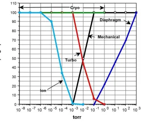
Due to the different molecular behavior in the four vacuum regimes described before, different types of pumps need to be applied to be able to achieve the UHV level. Figure 3.1 shows the typical operating pressures for different types of pumps. Remember that an ultimate pressure of 5x10-12 Torr is desired for this project. The figure reveals that surely an ion pump is needed to achieve this goal.
Figure 3.1 – Typical pump pressures (6)
The correct sequence of pumps turns out to be very important. In the new setup a dry mechanical diaphragm pump, a turbo-molecular pump and an ion pump are applied. These pumping principles are explained.
16
3.1.1 Diaphragm pump
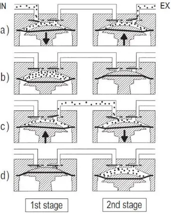
[image:17.612.216.387.283.497.2]A diaphragm pump is a dry mechanical pump used in the lower vacuum regimes with higher pressures, as can be recognized in Figure 3.1. This type of pump makes use of a flexible membrane that is driven by a crank. The membrane is an air-tight seal between the suction chamber and the mechanical driving system, which ensures a dry way of pumping gasses out. There is no oil contamination. Figure 3.2 shows the working principle of a 2-stage diaphragm pump. When the crank moves down, gasses from the vacuum chamber get sucked in at the inlet. When the crank is in outmost downward position, the inlet valve closes. Then the crank moves up, opening the outlet valve and pushing the gasses out of the suction chamber. This way, the pump creates a pressure gradient in the vacuum chamber, which causes gas molecules to diffuse towards the inlet. The diaphragm pump can be used the other way around as compressor. A clear animation of the working principle of a diaphragm pump can be found at the website of Thomas by Gardner Denver (9).
Figure 3.2 – 2-stage diaphragm pump working principle (10)
Due to its design, the diaphragm pump has a limited compression ratio. An ultimate pressure of around 50 Torr can be achieved by a one-stage pump. Connecting multiples stages can decrease the ultimate pressure up to 0.4 Torr (11). Figure 3.2 shows for instance two stages in series. The diaphragm pump that is used in the laboratory of DMI is a MVP 015-design by Pfeiffer Vacuum with a pumping speed of 15 L/min, see Appendix A. This pumping speed is merely limited by the dimensions of the suction chamber.
3.1.2 Turbo-molecular pump
17
blades rotate at very high speeds. Gas molecules from the vacuum chamber are then absorbed by the blades and after period of time transferred in the direction away from the chamber. The blades must not be slowed down from impact by other molecules, therefore the mean free path must be greater than the blade spacing. This is the case in the molecular flow regime (12). The turbo-molecular pump is a so-called kinetic pump. This type of pump suffers from a backflow caused by counter-pressure. The volume flow rate decreases with increasing pressure and becomes 0 at maximum compression ratio. The principle of a turbo-molecular pump is better suited for high mass molecules. The compression ratio and pumping speed for hydrogen (H) are significantly lower than for nitrogen (N). The principle is not appropriate for the viscous flow regime, which arises at the outlet of the pump for high compression ratios. Hence, a backing pump is needed here. At DMI the turbo-molecular pump and diaphragm pump are therefore always connected in series.
[image:18.612.252.357.382.516.2]The turbo-molecular pump used by DMI is the HiPace® 80 by Pfeiffer Vacuum, see Figure 3.3. The bearings of the rotor of this pump are designed as such, that the lubricants cannot contaminate the vacuum chamber. The rotor has a maximum speed of 90,000 rpm. The pump has an ultimate pressure of 3.75x10⁻¹⁰ Torr. The volume flow rate (for Nitrogen) is 67 L/s. This is much higher than the pumping speed in L/s seen for the diaphragm pump, but one must realize that the turbo-molecular pump operates in lower pressures and hence the speed in molecules per second lies in comparison lower.
Figure 3.3 – HiPace 80 turbo-molecular pump by Pfeiffer vacuum
3.1.3 Ion pump
An ion pump is applicable in lower pressures and must be used to achieve UHV. This is a type of pump of the gas-binding class (13). This classification can be immediately made clear by explaining the principle. In comparison to the earlier explained pumps, the ion pump does not pull gas molecules towards the pump inlet. The pump has to wait for the moment that a gas molecule floats into, in order to absorb it.
18
magnetron motion (14). The electrons are bound to hit gas molecules that enter the ion pump from the vacuum chamber. On collision of a free electron with a gas molecule, a positively charged ion is formed. This ion accelerates towards the titanium cathode. When the ion hits the cathode with great speed, sputtering occurs. The gas ion is absorbed in the cathode, while titanium compounds are sputtered on the anode surface. It is seen over time that the anode surface gets covered by a small titanium compound layer, which forms the cover that prevents release of gas molecules back into the system. The titanium cathode plates get saturated by absorbing the gas molecules. This is why they need to be replaced after a period of use. Based on this information, it is clear why an ion pump cannot be exposed to high pressures. The cathode plates would get saturated very fast and become unusable. The ion pump principle is nicely explained by Gamma Vacuum (14).
Figure 3.4 – a) ion pump interior (15) and b) 400L ion pump exterior (16)
DMI owns the TiTan 400L ion pump by Gamma Vacuum, shown in Figure 3.4b. For this type of pump, no speed or compression ratio can be specified because of its absorption principle. The starting pressure is specified as 75x10-4 Torr, at the start of the HV regime. The ultimate pressure lies below 1x10-12 Torr (16), which is required for the goal pressure of this project.
The ion pump was specifically purchased for the new FERP-system. The current research setup in the laboratory features the diaphragm pump and the turbo-molecular pump and is for that reason only specified for high vacuum. Once the ion pump is added, the step towards ultra-high vacuum is made easily. However, the desired vacuum level is 5x10-12 Torr. Professional use and strict design of the new research setup is therefore demanded. The use of the correct flanges and additional equipment like the TSP is very important here.
3.1.4 Other types of pumps
19
cost consideration. The other important reason to not use a pump is the possibility of lubricants entering the vacuum chamber. This is for instance seen for the rotary vane pump, a so-called wet pump with a mechanism based on oil. For UHV application at DMI, the use of dry pumps is essential. This is case for the diaphragm pump, turbo-molecular pump and ion pump.
3.1.5 Pump sequence
[image:20.612.167.456.244.495.2]In the foregoing sections it is seen that the different pumping principles are applicable in a certain pressure range. To conclude the information on vacuum pumps, the sequence of pumps for the new setup at DMI can now be clarified. To this end, see Figure 3.5. Here the relative pumping speed for different pumping principles is set out against the pressure in Torr.
Figure 3.5 – relative pumping speed (17)
It is seen that the diaphragm pump (purple line) loses functionality fast with decreasing pressure. The turbo-molecular pump (red line) becomes effective once the molecular flow regime is reached. Its ultimate pressure around 1x10-11 Torr is not presented in this graph. The ion pump (blue line) becomes useful at lower pressures and can reach a theoretical pressure below 1x10-13 Torr. The entrapment principle of this pump also works on higher pressures, but this would result in saturated cathode plates which would make the ion pump unusable very fast. The blue line does for that reason does not represent a possible relative pumping speed, but rather an advice on when the ion pump should be activated.
20
3.2 Vacuum gauges
Pumps are used to generate a vacuum, but cannot indicate which vacuum level is reached. Vacuum gauges are used for this purpose. As was seen with the vacuum pumps, also for gauges holds that different types are only applicable in a certain range of pressure. Multiple gauges are needed to describe the complete pressure range from atmospheric pressure to the desired UHV level of 5x10-12 Torr.
Direct gauges measure the pressure independently of the composition of the gas being measured. Indirect gauges are dependent on the composition of the gas being measured, such as the thermal conductivity (6). Indirect gauges need for that reason to be calibrated, dependent on the gas mixture present in a system. In the future setup three gauge types are included: Pirani, Penning and Ion Gauges.
3.2.1 Pirani - thermocouple gauge
The first gauge of interest is the Pirani – thermocouple gauge. There is a slight difference between these gauges based on manufacturer, but they work following a similar principle. The Pirani gauge is an indirect gauge. The measurement is based on the thermal conductivity of the gas it is placed in. A hot wire in a tube is placed in the gas, another wire placed in a reference gas. The wires are connected in a standard ‘Wheatstone bridge’ (6), see Figure 3.6. The first wire loses heat to the gas around it. While the temperature of the wire is maintained, is the current needed to do this the measure for gas pressure. If the pressure is high, there are a lot of gas molecules to transfer heat and the wire loses heat fast. If the pressure decreases, there a fewer gas molecules to transfer heat and there is a lower electrical current required to maintain the temperature of the wire constant. Hence, the electrical current required is an indirect measure of the vacuum level. At pressures below 1x10⁻⁴ Torr there is so little gas present that the gauge cannot provide an
[image:21.612.226.388.543.699.2]accurate reading (6). The composition of the gas significantly affects the reading (accuracy) of these gauges. Normally the gauges are calibrated for air (78 percent nitrogen) and a factor must be applied to the reading for argon, helium, or hydrogen. Argon absorbs heat much faster than nitrogen, while nitrogen is much faster than helium or hydrogen. As the pressure decreases the offset due to the gas composition decreases as well (6).
21
3.2.2 Penning gauge
The Penning gauge is also called a cold-cathode ionization gauge, which relates to its working principle. The gauge features a confined cold cathode and an anode placed inside a magnetic field. Ions present in the gas accelerate towards the cathode and upon interaction release electrons. The low pressure and high voltage cause a plasma discharge with an electron bombardment towards the anode. Due to the magnets placed outside the cathode, the electrons move along a helical path, which increases their effectiveness (18). If the gas molecules are hit, they are ionized and accelerate towards the cathode. Ion impacts on the cathode are measured and reported by the electronics of the gauge (6). Penning gauges are significantly influenced by the gas
composition and thus of the indirect type. Because a glow discharge is required for this type of gauge to operate, it does not work at pressures above 1x10⁻² Torr. Some inverted magnetron cold-cathode gauge types are specified for pressures up to 1x10-11 Torr, in the UHV-regime (19).
3.2.3 Ion gauge
The Ion gauge is also called a hot-cathode ionization gauge. The working principle lies close to that of the Penning gauge. For this gauge type, often the Alpert design is used. The Bayard-Alpert gauge applies a heated filament cathode as the source of electrons. These emit towards an anode grid. On their way from the emitter towards the anode grid, the electrons ionize gas molecules. These molecules accelerate towards a nearly grounded ion-collector. The impact of ions creates a current which is measured by the electronics. At a constant filament-to-grid voltage and electron emission current, the rate that positive ions are formed is directly proportional to the pressure in the gauge for pressures below approximately 1x10⁻³ Torr (20). The hot cathode principle of the Ion Gauge extends the readable pressure range of the Penning principle.
The Bayard-Alpert gauge used by DMI is the UHV-24p design from Agilent Technologies, see Figure 3.7 on the next page. The limit of this gauge lies at 5x10-12 Torr. This explains the limit set for this project. The vacuum level of 5x10-12 Torr is the minimum pressure for which an accurate reading can be given by the used equipment. For the pressure range between atmosphere and 1x10⁻⁹ Torr, DMI uses a combination gauge of Pirani and inverted magnetron cold-cathode technique, installed on the sample introduction chamber, see section 5.1. On the main chamber, a Pirani gauge and the hot-cathode Bayard-Alpert gauge are installed.
Direct gauge example: capacitance manometer
22
Figure 3.7 – Bayard-Alpert design Ion gauge in DMI laboratory
3.3 Vacuum flanges
Up to this point a description of a range of vacuum pumps and gauges is given. This equipment, like all other vacuum equipment, needs to be connected in a vacuum system somehow. A
connection between vacuum parts needs to be airtight to retain the low pressure inside. Different standards are developed for this purpose.
[image:23.612.211.402.68.305.2]Two types of standard vacuum flanges are found in the laboratory of DMI. There are the KF- and CF-flanges. KF-flanges feature a rubber ‘o-ring’ as the seal for airtight connection. In CF-flanges, this function is provided by a soft metal gasket, made from copper in most cases. Figure 3.8 shows the two different types and corresponding airtight seals in the inventory of DMI.
23
3.3.1 KF Flanges
KF is short for Klein Flange. Figure 3.9 shows an exploded view of this flange type. The two tubes on the outside are connected to other parts of a vacuum setup, for instance a pump or chamber. The black ring is a rubber o-ring, which functions as the airtight seal. It is placed around a
centering-ring that aligns the flanges and holds the o-ring in position. The connection is hold together by the clamp, which closes by tightening the wing nut.
Figure 3.9 – exploded view KF-flange (22)
KF flanges are appropriate for pressures to 1x10⁻⁸ Torr (23), so UHV cannot be reached. This type of flange suffers from outgassing. Gas molecules trapped in the o-ring escape in the lower pressure ranges. The use of KF-flanges is cost-effective, because the o-ring seal can be re-used. This is not the case with CF-flanges, as explained below. The low price made this type of flange interesting for DMI for the old research setup, but is due to its limits not applied in the future system.
3.3.2 CF Flanges
The CF-flange type was developed by Agilent technologies and set a new standard for vacuum applications. CF is short for ConFlat, a name variation on the older KF type. CF-flanges are tested for pressures to 1x10-13 Torr (24), therefore ideal for the UHV application as desired by DMI. Figure 3.10a shows the exploded view of a CF-flange, Figure 3.10b shows the mated cross section.
24
Both flange sides in Figure 3.10 are identical. The orange part in between is the soft metal gasket. A knife-edge that is machined below the flange’s flat surface provides the seal mechanism. As the bolts are tightened, the knife edges make annular grooves on both sides of the copper gasket. The extruded metal fills all the machining marks and surface defects in the flange, yielding a leak-tight seal (24). Because the copper gasket gets deformed after the flanges impurities, it can be used only one single time. It is not reusable, as was the case for the o-ring seal. Out of cost
consideration, some CF-flanges in the current setup at DMI are therefore equipped with o-rings instead. The o-ring is placed inside the space for the gasket and the flanges are tightened by using bolts in only half of the bolt-holes. This results in a connection that is only appropriate for high vacuum, and hence this improper use of the flanges cannot be done in the new FERP-system.
CF-flanges are in general produced from stainless steel 304L or 316L. This type of steel does not have residual magnetic properties, which could interfere with test results in most research applications. This industry standard is also used at DMI; all flanges and other type of connections are produced from these steel types. This requirement holds for all designs within this project.
3.3.3 Sizes and versions of CF-flange
All pumps, gauges, chambers and other equipment in the future setup are connected using the CF industry standard. CF flanges of different sizes need to be applied. In Figure 3.3 could for instance be seen that the HiPace 80 Turbo-molecular pump is equipped with a CF flange. Figure 3.4b shows a CF-connection on top of the ion pump. Based on the amount of bolts needed, it can be seen that these flanges have different sizes. Because CF is an industry standard, the flange sizes are
standardized. Standard sizes are indicated by ‘DN - tube size’, shown in Table 3.1 (25).
Metric Inches Outer diameter
(mm)
Tube Inner diameter (mm)
DN16 1-1/3 34 16
DN40 2-3/4 70 35
DN63 4-1/2 114 60
DN100 6 152 100
DN150 8 203 150
Table 3.1 – standardized CF-flange sizes
Besides different sizes, there are different versions of the CF-flange. Typically needed are
25
Most variations on the standard CF-flange are seen in the later design stage. Out of cost
consideration, DMI does not purchase flanges from manufacturers, but purchases stainless steel 304L or 316L disks that are machined down to a flange in the workshop. To this end, DMI uses a standard handbook with technical drawings of all flange sizes and types (26). This handbook is provided by LNLS, the Brazilian Synchotron Light Laboratory, a large facility that is also located in
Campinas. See http://lnls.cnpem.br/.
3.4 Other equipment
With the vacuum pumps, gauges and flanges, a large part of the equipment is discussed. But these parts are not nearly enough to build the complete system as desired by DMI. Other parts that are required are discussed in this section. This concerns parts that have been newly purchased or that were already present in the stock of DMI. Figure 3.11 shows a large order of parts that DMI received from Kimball Physics during the internship period. Note: the red and yellow plastic covers on the CF-connections function to protect the parts from dust and other contaminants.
Figure 3.11 – purchased parts that will be used for the future setup
3.4.1 Spheres
Up to this point the term ‘vacuum chamber’ was repeatedly mentioned. The main vacuum
26
3.4.2 Viewport
Figure 3.11 shows a viewport top-center. This is a special type of flange, equipped with a glass window of sufficient thickness. Elastomeric seals are used to attach the glass. The glass is
metalized and soldered, or fused with welding lips to compensate for the thermal expansion. This way, a connection is made that is appropriate for UHV-application.
The new setup features two viewports, one on both spherical cubes. These viewports make sure that the researcher can visually observe operations inside the system. In the main chamber must for instance be checked whether the FERP sample plate (section 2.1) is positioned correctly.
3.4.3 Gate valves
Gate valves are used to (temporarily) separate parts of a vacuum setup. It is practically a doorway that can be shut leak-tight, UHV specified. Gate valves come in many different forms and sizes. They work either electro-pneumatically, electromagnetically or manually. The first two types are ideal for automated vacuum processes. For the FERP-research at DMI however, the manual type is preferred. Two manual valves with DN63 CF-connections by MDC vacuum are used. One of these can be recognized top left in Figure 3.11. Possibly another, larger gate valve should be included in the setup, this is discussed in section 4.3. The functioning of the gate valves becomes clear in the procedure, section 5.2.
3.4.4 Transfer arm
A magnetic transfer arm is used to transfer the FERP-sample plate from the small sphere towards the main chamber. Like gate valves, transfer arms come in many different forms and sizes, and with different degrees of freedom to control. DMI purchased a 12” magnetic transporter by MDC Vacuum, the long part on the left side of Figure 3.11. A simplified dimensional drawing is shown in Figure 3.12.
Figure 3.12 – 12 inches magnetic transporter by MDC Vacuum (27)
27
specific sample holder is designed for this purpose, to which University of Twente student Tijmen van Diepen contributed (28).
This transfer arm has a 12” raceway, However, if the stop clamp on the right side of Figure 3.12 is removed, the translational DOF is extended to 16 inches. This turns out to be required in the later design stage.
3.4.5 Residual Gas Analyzer
The residual gas analyzer or RGA is a device that helps to identify the residual gases in a vacuum system. While the gauges described in section 3.2 only provide an overall pressure, the RGA is able to identify the contribution of partial pressures of different molecule species. This identification is based on molecular masses and the mass-to-charge ratio. The RGA technology is not further explained here, but extensive studies on the complex behavior can be found in literature (29). To illustrate the use of it, Appendix B shows a plot that is obtained with the RGA for the current research setup at DMI. Here it can be recognized that water is the most present contamination, a factor 10 times more present than other species. Therefore, water is also playfully given the nickname ‘great enemy’ by Vinicius L. Pimentel. A device that helps to remove water from the vacuum chamber, is the TSP-Cryoshroud.
3.4.6 TSP Cyroshroud
In earlier sections a TSP or Titanium Sublimation Pump was already mentioned. In the future setup, the TSP is combined with a cryoshroud. The TSP-Cryoshroud is a standard combination delivered by Gamma Vacuum, often used in combination with an ion pump (30).
The TSP is a small device that contains three titanium (Ti) filaments, see Figure 3.13a on the next page. When used, a 50A current is put through a filament, which starts to evaporate. The Ti-vapor
reacts with contaminating gases (H2, CO) and water (H2O). The products from this chemical
reaction form a thin film on the inner surface of the vacuum chamber, covering the contamination and the absorbed water. This process can only take up to 4 minutes, due to the high current and the lifetime of the titanium filament.
The liquid cryoshroud consists of a thin-walled stainless steel cylinder with two feedthroughs, see Figure 3.13b. The feedthroughs are used to fill the cylinder with cooling liquid. With cooling water,
the TSP pumping speed (for H2O) increases to 5,000 L/s. With liquid nitrogen, a pumping speed
(for H2O) of 20,000 L/s can be achieved. Hence, it is very useful to get rid of water molecules inside
the system. To compare, the TiTan Ion Pump (section 3.1.3) has a maximum pumping speed of
‘only’ 400 L/s for nitrogen (N2). Combining the ion pump and TSP-Cryoshroud allows for low
28
Figure 3.13 – a) TSP cartridge and b) liquid cryoshroud cylinder
Note that the TSP is placed inside the cryoshroud and hence much smaller, which can be
recognized based on the flange sizes in Figure 3.13.The cryoshroud is standard equipped with a
DN150 CF-flange. To include this device in the new research setup, a separate chamber is designed. This is called the ‘crossing’, discussed in section 4.3.
3.5 Outgassing and bake-out
In order to achieve and maintain the desired UHV-level of 5x10-12 Torr, the equipment needs to be treated carefully. Parts must be specified for minimum release of gas molecules from the surfaces into the system, called outgassing. A bake-out procedure can be used to significantly increase outgassing before operation, which decreases pumping times (31). The amount of water molecules that can desorb (type of gas molecules release) during operation is then minimized. DMI wants to apply a bake-out temperature of 150 °C for the new FERP-system. Figure 3.14 shows the ‘oven’-setup that is used for a bake-out.
Also, the walls can be cleaned by the use of plasmas, by putting an electric current through the low pressure environment. Contamination on the chamber walls can beforehand be minimized by the use of gloves while handling vacuum equipment.
29
4 Design
Now all commercial vacuum equipment for the new setup is discussed in the previous chapter, design of the required parts to complete this setup can be carried out.
4.1 From quick concept to final design
During his internship at CTI in 2014, Jildert Anema made a quick concept of a new research setup (1). This concept functioned to acquire the required budget to buy necessary commercial parts. DMI received the budget and purchased this equipment. However, some changes have been made to the quick concept. A new CAD-model is therefore desired. This model should include the
changes that are made and provides detail for the parts that still need to be designed. This means that all connections between the commercial parts need to be detailed up to the level that they can be manufactured by the workshop. The end product of this internship for the detailed final setup is therefore a complete CAD-model with technical drawings of all the parts to be
[image:30.612.158.463.342.624.2]manufactured. Figure 4.1 shows the initial quick concept by Jildert Anema.
Figure 4.1 – front view of CAD-model of (initial) quick concept (1)
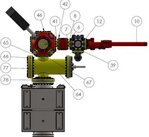
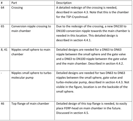
All yellow colored parts in Figure 4.1 need a detailed design for manufacturing. The most
30
# Part Description
64 Crossing A detailed redesign of the crossing is needed,
described in section 4.3. Note that this is the chamber for the TSP-Cryoshroud.
65 Conversion nipple crossing to
main chamber
Due to the redesign of the crossing, a new DN150 to DN100 conversion nipple towards the main chamber is needed in this location. This detailed design is
described in section 4.4.1.
8, 41 Nipples small sphere to main chamber
Detailed designs are needed for a DN63 to DN63 nipple between the small sphere and the gate valve and a DN63 to DN100 nipple between the gate valve and the main chamber. Described in section 4.4.2.
- Nipples small sphere to
turbo-molecular pump
Detailed designs are needed for two DN63 to DN63 nipples between the small sphere, gate valve and turbo-molecular pump, described in section 4.4.3. Not visible in the figure, location is on the backside of the small sphere.
46 Top flange of main chamber Detailed design of this top flange is needed, to easily
[image:31.612.88.530.69.472.2]place FERP-head on main chamber in the future. Discussed in section 4.5.
Table 4.1 – required (re)designs
The yellow colored parts that are not mentioned in the table, are CF Flanges that can be
manufactured by the workshop using the LNLS handbook (26). Furthermore, minor adjustments to the CAD-model are needed. The large two-stage ion pump on the bottom in Figure 4.1 is replaced by the Gamma Vacuum TiTan 400L. And possibly, a large gate valve will be placed between the crossing and the ion pump (location 78) in the future. This is discussed at the crossing design in section 4.3.
4.2 Requirements
In the foregoing chapters it was seen that design for vacuum systems is mostly limited to standardized equipment based on standard vacuum requirements. Besides these standard requirements, CTI has demands that make the final setup achievable. For instance, based on costs and available production methods. Table 4.2 summarizes the requirements for designs in
31
1. For all metal parts, the material to be used is stainless steel 304 or 316L. This steel type
does not have residual magnetic properties that could affect research results.
2. The dimensions of each part should be as such that easy assembly within the complete
setup is guaranteed.
3. All tubular connections should at least contain one rotatable flange. This degree of
freedom is needed for easy assembly of a large configuration.
4. Parts need to be produced at CTI workshop or LNLS workshop, machining processes are
therefore limited to milling, turning and laser cutting. In certain cases, an external manufacturer may be invoked, known by DMI.
5. All CF-Flanges are manufactured following the LNLS handbook (26), tolerances from this
handbook need to be used.
6. All production costs should be kept as low as possible. There is no budget available, this
needs to be acquired based on the designs.
7. All parts need to be able to withstand temperature up to 150°C, which is the temperature
used in the bake procedure.
8. The conductance (not mentioned before in this report) of a part should be kept as high as
possible. This means for tubes that short lengths and large diameters are demanded. In practice these diameters are determined by the flange sizes of commercial equipment.
Table 4.2 – requirements for designs for new vacuum setup
4.3 Crossing
The first part to be (re)designed is the crossing between the main chamber and the ion pump. This crossing is used to place the TSP-Cryoshroud, explained in Section 3.5.6. The initial design of Jildert Anema (part 64 in Figure 4.1) was based on the DN100 connection towards the main chamber on top. It was made such that the cryoshroud was not blocking the air flow from the main chamber towards the ion pump, clearly shown in Figure 4.2. This resulted in an asymmetric design, with weight concentrated on the right side of the crossing.
32
The idea of making an asymmetric part because of the airflow is not needed. The TSP-Cryoshroud may partly block the flow from the main chamber, although this seems bad for conductance on first hand. It would badly affect the flow in the viscous flow regime, but not in UHV, which is present in this part of the setup. Only a gap is needed, sufficient for molecules to pass towards the inlet of the ion pump below. It is possible to make the crossing symmetric, which is preferred for the ease of production and assembly.
Besides making the crossing symmetrical, another adaption is needed. Because of the possible placement of a large DN150 gate valve (Figure 4.3) on top of the ion pump in the future, the DN100 CF-flanges of the crossing need to be replaced by DN150 versions. This gate valve should protect the ion pump from contamination by particles from other locations in the system, when these are in higher pressure levels. This is an idea for the future, because bake resistant large gate valves are commercially available, but expensive. DMI currently lacks the budget to buy a
[image:33.612.238.376.285.460.2]$4.365,00 large gate valve, as the DN150 version by MDC Vacuum.
Figure 4.3 – DN150 gate valve by MDC vacuum
Note that with this redesign a DN100-DN150 conversion nipple towards the ion pump (or gate valve) is not needed anymore. However, a DN150-DN100 conversion is now needed on the other side, towards the main chamber on top. This design is discussed in section 4.4.1. If the large gate valve will be purchased, is still up for discussion. Nevertheless, it is chosen to provide the crossing with four DN150 connections, because this results two-way symmetrical design.
4.3.1 New crossing design
The adjustments to the initial crossing design are rather simple. The TSP-Cryoshroud is moved towards the center and the DN100 CF-flanges are replaced by DN150 versions. This means that the tube size and conductance increase. The redesign is carried out stepwise, as described below.
33
Figure 4.4 – first changes to old design and leftover airflow space
There is enough space for molecular flow towards the ion pump, but immediately it can be seen that a problem arises with the assembly of this design. This problem occurs with the bolts for the top and bottom flange. The bolts that are used to fix the DN150 bottom flange of the crossing to the DN150 top flange of the ion pump have a length of 60 mm including the head. The height of the crossing must therefore be adjusted, to leave enough space for easy placement of these bolts (requirement 2). Furthermore, the width can be reduced to save material and weight. The gap for the air flow left can be minimized. The following step concerns extension of the height and reduction of the width.
To make these changes easily, a CAD-model of the bolt is made in SolidWorks. In the CAD-model of the crossing, this bolt is placed where the distance between the bolt hole of the flange and the tube is minimal. The distance required here, defines the new height of the crossing: 317 mm including the two CF-flanges. In the assembly process a CF-flange is placed around the tube and then welded. The amount of tube that enters the DN150 flange is 9.5 mm. The total tube height then becomes 292 mm. This is clarified in the production of the crossing, section 4.3.2.
At this point, it would be convenient to produce a two-way symmetric crossing. In that case, it would not matter how the crossing is assembled in the complete research setup, which leaves less chance of error. The tube’s width is therefore reduced to the dimension of 292 mm. Figure 4.5 illustrates the leftover space for the air flow, which is the other important design parameter.
34
The gas molecules only need a very small space to pass towards the ion pump, according to Vinicius L. Pimentel. In practice, the ion pump will be activated during a few days, before an actual FERP-experiment. It slowly removes particles from inside the system. This is a statistical process, as explained in section 3.1.3. The gap in Figure 4.5 could for that reason be reduced even further, but this is not done. With sufficient space for the passage of particles inside, sufficient space for the placement of the required bolts on the outside and a two-way symmetric design for the ease of production and assembly, this is the optimal crossing design for this application.
4.3.2 Crossing part dimensions and production
The new crossing basically consists of 5 parts: 1 tubular part and 4 DN150 flanges. The way they are produced is shortly discussed here.
Tubular part
The exact dimensions of the tube depend on the connection to the flanges and the space required for placement of the bolts. The tube height and width are determined to be 292 mm. The flanges are welded onto the tube. To this end, the tube enters the flange a little distance. This is a standard way to connect tubes and flanges in vacuum applications.
This dimension can be recognized in the technical drawing of a DN150 flange in Figure 4.6. The tube enters from the bottom. The 9,5 mm dimension is of importance here. This is part where the tube enters the flange. A weld is made in the corner at the end of this 9,5 mm track, to fix the flange to the tube.
Note that the knife-edge of the flange is on top in Figure 4.6. This is where the copper gasket is placed for the connection to another flange.
Figure 4.6 – technical drawing of the cross section of a DN150 CF-flange (26)
The tube size is dependent on the external manufacturer. Appendix C shows the standard sizes of the materials supplier for DMI. It can be seen that in case of a DN150 configuration, a tube with an outer diameter of 152,1 mm is delivered. One might recognize that this tube size fits within the 153 mm diameter of the flange seen in Figure 4.6. For a two-symmetric design with the bolt lengths of 60 mm, it can be concluded that the following height and width are needed:
35
This dimension is rounded up to 292 mm. This finding supports the dimension found with the CAD-models in the previous section. One might say that the margin of 0.45 mm on both sides to place the bolts is small. However, the bolts can be placed easily under a small angle. It might also be expected that the use of a weld between the tube and the flange increases the height a bit. But according to Vinicius L. Pimentel, based on experience, the resulting change in dimension can be neglected.
[image:36.612.219.395.231.398.2]The final tube design has a width and height of 292 mm. The tubes have a standard other diameter of 152.1 mm and an inner diameter of 148.1 mm. The wall thickness is 2 mm. The design is shown in Figure 4.7.
Figure 4.7 – design of the tube
Appendix D contains a detailed technical drawing of the tube design. This can be used to manufacture the part.
Manufacturing of the crossing needs to be precise. The seams must be leak-tight with the UHV-application. According to Vinicius L. Pimentel, the external manufacturer and supplier of the required parts, has made this kind of structures in the past using a specific manufacturing process. With a specialized drill, a hole is made in a tube, by which the tube material is extruded along the drill. Another tube can then be welded onto the tubular extrusion that is made. The question is whether this process works for the crossing, in which both tubes have the same diameter. The required manufacturing process is therefore left to the experience and insight of the external manufacturer, and not further discussed here. The type of connection that needs to be manufactured, can be recognized in Figure 4.8 below.
Flanges
36
be used, small misalignments between the holes of the ion pump (or gate valve) on the bottom and the nipple towards the main chamber on top would cause problems. It would result in undesirable or even impossible placement of the parts. A small misalignment in the start of the assembly, can result in large misalignments in other parts. To be able to assemble the complete setup as desired, rotatable flanges are applied. These ‘rotary flanges’ consist of a fixed part and rotatable part. The fixed part contains the knife and is welded onto the tube. The rotatable part contains the bolt holes and can move freely around the tube. Figure 4.8 shows the fixed and rotatable parts of a rotary flange on another piece of equipment in the laboratory of DMI.
Figure 4.8 – fixed and rotatable part of a rotary flange
For the production of the flanges, DMI receives raw material. For each flange a stainless steel 316L solid disk is required. In case of the DN150 flanges, this disk should at least have a thickness of 22 mm, see Figure 4.6. In the workshop at CTI, the disk is then formed into a flange by applying turning and milling, following the designs of the LNLS handbook.
Assembly of crossing
When all five parts are manufactured, the crossing can be assembled. To this end, the two CF150PD flanges and the fixed parts of the CF150RR flanges are welded to the 4 ends of the tube. Special attention need to be paid to the assembly of the rotary flanges. The rotatable part must first be placed, before welding the fixed part to the tube. Otherwise the rotatable part cannot be placed anymore and the flange needs to be disassembled. This problem might be recognized by
thinking of how the flange in Figure 4.8 was placed. Figure 4.9on the next page shows the new
37
Figure 4.9 – new crossing design and exploded view
4.4 Nipples
The connections between the purchased commercial parts need to be realized. These connections are called ‘nipples’ in vacuum technology. A nipple basically consists of a tube and two flanges, used to connect to other vacuum parts. As an example, Figure 4.11 shows a typical nipple from a research setup at the LNLS laboratory. This nipple forms a connection between a sphere and a gate valve.
Figure 4.11 – Typical nipple in setup at LNLS
38
4.4.1 Nipple between main chamber and crossing
The first nipple design to be addressed is the one from the main chamber towards the crossing. It was mentioned in section 4.3 that a DN150 to DN100 conversion is needed here. There are no difficult requirements for this design, apart from the fact that (again) the bolts need to be placed easily. The basic design consists of a DN100 flange to a DN150 flange, with a DN100 tube in between.
Because of the two different flanges, two different types of bolts are needed. The connection towards the crossing is made using the 60 mm bolt mentioned in the previous section. This bolt goes entirely through the holes of the nipple and the crossing, to be tightened by a nut on the other side of the flange. The second type of bolts is needed for the connection to the main chamber. Here, a 39.3 mm silver plated bolt is used. This length is including the bolt head. These bolts are specified for the large sphere produced by Kimball Physics, and have therefore a thread that is dimensioned in inches. The spheres feature threaded holes in which the bolts can be fixed, another connection type than is seen at the side of the crossing. For clarity, both connection types are shown in Figure 4.12.
Figure 4.12 – two types of bolt connections, tapped holes and through-holes with nut
Figure 4.13 shows schematically the basic design of the needed nipple. The figure reveals that there is enough space around the CF100 flange to place the 60 mm bolts easily, which is later verified in the CAD-model of the complete setup. The distance between both flanges is determined by the length of the small bolt with its 39,3 mm in total.
39
Figure 4.13 – schematic view of nipple design between crossing and main chamber
[image:40.612.212.401.69.258.2]The final design and exploded view are shown in Figure 4.14. The total height of the nipple is 84 mm, with the flange thicknesses of 20 (DN100) and 22 mm (DN150). Technical drawings can again be found in Appendix D. It can be concluded that this first nipple design was very straightforward.
Figure 4.14 – first nipple design with exploded view
The production of nipples is also rather easy. Whereas the tubular part for the crossing in section 4.3 is difficult to produce, the tube here is plain and simple. The tubes for DN63 are standardized, see the Appendix C. The tubes are purchased with standard diameters and cut in the correct length. The flanges are produced by turning and milling of the blank AISI 316L steel disks. In the end, all parts are welded together, except for the free parts of the rotary flanges. Again, the order of assembly is of crucial importance here. The rotatable part of the rotary flange should be placed around the tube before welding the fixed part. If a mistake is made here, a complete new nipple must be manufactured.
4.4.2 Nipples between small sphere and main chamber
40
related by space limitations. The maximum length depends on the FERP-sample transfer, whereas the minimum nipple size is yet again determined by the space needed to fix the bolts.
[image:41.612.175.443.259.473.2]It was explained in section 3.4.4 that the extended reach of the transfer arm is limited to 16 inches. This is where this DOF comes to use. The magnetic transfer arm is used to transfer the sample from the pre-vacuum chamber (small sphere) to the main chamber. The specified sample holder is placed on the end of this transfer arm. As a start, the sample is located in the perfect center of the small spherical cube. From this position, once the vacuum is at desired level, the sample is transferred through the first (to be designed) nipple, the small gate valve and the second nipple, towards the main chamber. This distance is thus limited to the 16 inches’ reach of the transfer arm. The dimensions of the gate valve and both spherical cubes are known, the combined length of the nipples needs to be limited. Figure 4.15 illustrates the leftover design space.
Figure 4.15 – available space for design of nipples
16” = 406.6 mm. The radius of the small spherical cube is 62 mm. The radius of the main chamber
is 106,4 mm.The width of the small gate valve is 70,1 mm. Hence, the leftover design space for
the two nipples is:
406.6 𝑚𝑚 − 106.4 𝑚𝑚 − 70.1 𝑚𝑚 − 62 𝑚𝑚 = 168.1 𝑚𝑚
41
inches- and mm-dimensioned bolts are shown in Table 4.3. With the maximum length and applied bolts known, the nipple designs can now be detailed.
Silver plated bolts (thread in inches)
Used in spherical cubes threaded holes
Standard bolts (thread in mm)
Used in gate valve threaded holes
Thread length: 1 ¼” = 31,75 mm Head length: 7.6 mm
Total length: 39.3 mm
[image:42.612.95.517.110.276.2]Thread length: 29,5 mm Head length: 5.6 mm Total length: 35.1 mm
Table 4.3 – applied bolts
Design nipple 1: Small sphere to gate valve
The first nipple is the connection between the small sphere and the gate valve. The standard design of this nipple consists again of two flanges and a tube. The flanges are in this case a standard DN63 and a rotatable DN63, as required for alignment.
This nipple must be designed as short as possible. The distance between the two flanges must therefore be minimized. The minimum distance is equal to the bolt length. The alignment of the bolt holes matters here, as clearly indicated in Figure 4.16.
Figure 4.16 – difference holes aligned or not
[image:42.612.165.471.442.635.2]42
[image:43.612.248.363.129.244.2]Physics did already put their thoughts on this opportunity. Their spherical cubes feature twice as many threaded holes as needed for the CF-connection. In case of the small 4.5” sphere, there are 16 holes instead of the 8 that a normal DN63 CF-flange features, see Figure 4.17.
Figure 4.17 – twice as many bolt holes on spherical cube (16 instead of needed 8 for DN63 connection)
This convenient design aspect has the result that the bolt holes of both flanges of the nipple can be shifted in relation to each other. In case of the DN63 flanges, the bolt holes (or flanges) can be rotated an angle of 22°30´ relatively to each other. Use of one rotatable CF63RR flange on the nipple, makes this easy. The flanges do not have to be fixed in the angle of 22°30´ in relation to each other, but this configuration can be guaranteed on the moment that the CF63RR is mounted onto the sphere or the gate valve, depending on the desired way of assembly.
In the desired final configuration of DMI, the small gate valve is placed in upright position. This way, the manual control of the valve can be carried out in the easiest way. The bolt hole locations of the gate valve in upright position can be recognized in Figure 4.18. Hence, on the small sphere the holes in between are used, which results in the convenient nipple configuration of Figure 4.16b. Note that if you look closely at the nipple-design of the LNLS setup in Figure 4.11, you can see that the bolt holes of the flanges are also not aligned.
Figure 4.18 – hole configuration gate valve in upright position (MDC small gate valve)
The distance between the two flanges needs to be at least the total length of the silver plated bolts: 39.3 mm. With the 17.5 mm thickness of two DN63 flanges added, the total nipple length
[image:43.612.240.370.495.630.2]