A Thesis Submitted for the Degree of PhD at the University of Warwick
Permanent WRAP URL:
http://wrap.warwick.ac.uk/78769
Copyright and reuse:
This thesis is made available online and is protected by original copyright. Please scroll down to view the document itself.
Please refer to the repository record for this item for information to help you to cite it. Our policy information is available from the repository home page.
Executive Summary - The Development
of Thermal Spray Tooling
RN Dunlop Dyson Research Ltd
Tetbury Hill Malmesbury , Wiltshire SN16 ORP
March 1999
Executive Summary - The Development of The17lUl1 Spray Tooling
Abstract
Thermal spray tooling is one of a number of technologies which have been developed to satisfy the need for low cost tooling, which is used when prototype components are required in the correct engineering material. In its current state, the technology has a number of
fundamental shortcomings. The aim of this portfolio was to address these shortcomings, via a combination of experimental work and technology demonstrators - these are summarised as follows:
• An experimental programme aimed to quantify many of the problems associated with thermal spray tooling. A wide variety of tests on thermal spray surfaces was carried out, in order to compare their performance with other 'low cost' tooling techniques. For the first time, tooling shells were produced using the High Velocity Oxy-Fuel (HVOF) technique. This system is capable of producing extremely high quality tool shells, and the technique developed involves the novel use of castable ceramic patterns - the first time a releasable pattern has been developed for this spray system. In addition, it was established that
'hybrid' tooling shells could be produced - these were formed using a combination of arc spray and HVOF layers. The work proved that these hybrid shells could provide substantial performance benefits in terms of wear performance and vacuum integrity, when compared to conventional arc sprayed shells - this benefit was also achieved without significant cost penalty. The programme also investigated the effect of thermal cycling on thermal spray samples - it was shown that repeated cycling at high temperature had an adverse effect on both arc sprayed and HVOF samples - the extent of this effect was very much dependent on the material.
• The portfolio includes a technology demonstrator programme, which was carried out for Rover Group to show the potential of thermal spray tooling. The programme entailed the manufacture of a suite of 5 tools for compression moulding of Glass Mat
Thermoplastic(GMT). The actual route used for the production of the tooling suite involved many unique features, which had not previously been utilised for thermal spray tooling production. One of the tools is the largest ever produced for compression moulding using thermal spraying, being approximately 4m2, and weighing in excess of 3 tonnes. Due
to the compressive stresses involved in the moulding process, conventional resin backing systems were unsuitable for this tooling. It was therefore necessary to use a Chemically Bonded Ceramic (CBC) material, with an exceptionally high compressive strength. However, this material does not adhere to thermal spray surfaces, and it was therefore important to develop a novel fixing method at the interface of the materials. Further to this, in certain cases the use of thermal spraying was precluded by the component geometry - in these cases it was necessary to use the CBC material as the direct tool face. This was the first time that CBC tooling had been used for compression moulding GMT, and it was therefore necessary to develop new post-treatments for this inherently porous material. The moulding operation then entailed the development of specific techniques and conditions for this prototype tooling, which would not generally be used in production - normal moulding conditions for 'production' tooling were therefore inappropriate.
Executive Summary. The Development of Themull Spray Tooling
Contents
Abstract
1.0 INTRODUCTION
2.0 THERMAL SPRAYING REVIEW
2.1 Thermal Spraying. Process Restrictions and Improvements 2.1.1 Background
2.1.2 Internal Stresses 2.1.3 Porosity 2.1.4 Oxidation 2.1.5 Summary
2.2 Mould Tooling using Thermal Spray Techniques
2.3 Cost Comparison for Thermal Spraying and other Tooling Routes
3.0 PHYSICAL PERFORMANCE OF THERMAL SPRAY TOOLING
3.1 Background
3.2 Pattern Materials
3.3 Tensile Properties 3.3.1 Tensile Strength 3.3.2 Flexural Strength 3.3.3 Thermal Fatigue
3.4 Wear Resistance
3.5 Vacuum Integrity
3.5.1 Effects of Post-Treatment 3.5.2 Effects of Backing Material 3.5.3 Elimination of Side Leakage 3.5.4 HVOF Material Thickness
4.0 COMPRESSION MOULDING PROJECT
Executive Summary - The Development o/Thermnl Spray Tooling
4.2 Tooling Manufacture
4.3 Personal Contribution
5.0 FURTHER WORK - STRATEGIC TOOLING REQUIREMENTS FOR MOULDING COMPOSITE STRUCTURES
5.1 Background
5.2 Programme of Work
5.2.1 Thermal Spray Surfaces & Backing Materials 5.2.2 Component & Tool Design
5.2.3 Pattern Materials 5.2.4 Hardware Development
5.2.5 Process Automation & Simulation
5.3 Personal Contribution
6.0 CONCLUSIONS
7.0 REFERENCES
8.0 BIBLIOGRAPHY
Appendix A • Summary of Portfolio Documents
36
41
42
42
44 45 46 47 47 48
50
51
55
58
Executive Summary - The Development of Thermal Spray Tooling
List of Figures
Figure 1: Electric Arc Spray System _ _ _ _ _ _ _ _ _ _ _ _ _ _ _ _ _ _ _ _ _ _ _ _ _ _ 1 Figure 2: Relative costs and lead times for tooling using different manufacturing routes 15
Figure 3: Machine usedfor tensile & flexural testing 20
Figure 4 : Flexural testing fixture 23
Figure 5 : Wear test rig 26
Figure 6: Comparative wear results for various materials 27
Figure 7: Loss of vacuum vs. time for thermal spray samples & benchmark materials 29
Figure 8: Positioning of extra vacuum tape layers 31
Figure 9: Effect of'side leakage' on vacuum integrity of zinc samples 32 Figure 10: Novelfixing method between Thermal Spray & Densit 35
Figure 11: Large tool (female half) during manufacture 37
Figure 12 : Flow chart showing tooling manufacturing route 38
Execwive Summary -The Developmellt of Thermal Spray Tooling
1.0 Introduction
The aim of this document is to summarise a portfolio of research undertaken in the field of
low cost tooling. There are now many technologies available for the production of low cost
tooling. These technologies are becoming increasingly important, with manufacturers under
ever-increasing pressure to reduce product development costs and lead times.
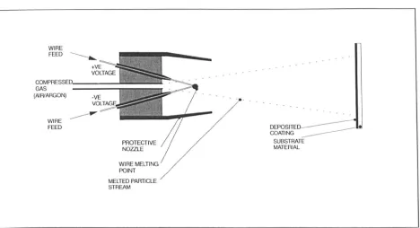
One technology which is finding increasing use for the production of low cost tooling is that
of thermal spraying (see Figure 1). Although thermal sprayed tooling has been in use for over
30 years [1], its use has been restricted due to lack of knowledge, and limitations in systems
and materials. Increasingly, however, the technology is gradually being accepted for use in
moulding applications such as blow moulding, rotational moulding, injection moulding and
Resin Transfer Moulding (RTM).
WIRE
FEED
GAS (AIR/ARGON)
WIRE FEED
PROTECTIVE NOZZLE
WIRE MELTING
POINT MELTED PARTICLE
STREAM
Figure 1: Electric Arc Spray System
The use of thermal spraying is still restricted, however, due to fundamental problems with the
use of sprayed surfaces for tooling. These are due to the physical properties of thermal sprayed
surfaces, the properties of the moulded material, the tooling geometry and many other factors.
This means that generally speaking, thermal spray tooling is only viable for low pressure
[image:7.534.37.505.333.587.2]Executive Summary -The Developme1lt of Thermal Spray Tooli1lK
the research portfolio is to improve the overall performance of thermal spray tooling, in order
that it may be used for a broader range of applications.
The portfolio is presented as a number of discrete documents, each fulfilling a specific
function. This report will summarise the contents of these documents, with particular
emphasis on the innovative content of each document -the innovative contribution will be
summarised in each individual project summary. Broadly speaking, the overall aims of the
portfolio may be defined as follows:
• To improve the physical performance of thermal spray tooling, allowing tooling to be used
in more challenging moulding environments, producing higher component volumes. This
will be achieved through an experimental programme, using improved thermal spray
methods and post-treatments to achieve improved tooling surfaces.
• To demonstrate the potential of thermal spray tooling as a medium for rapid component
production. This will be achieved through the manufacture of tooling for a particular
application, with demonstrable cost and lead time benefits.
• To define a package of work which will enable the automated production of thermal spray
Executive Summary - The Development o/Thermal Spray Tooling
2.0 Thermal Spraying Review
The intention of this section is to provide a critical review of the current state of development of thermal spraying as a group of technologies. The review will concentrate on some of the problems associated with thermal spraying, and how process improvements have alleviated these problems. Next, a section will analyse mould tool manufacture using thermal spray technologies, including current and future developments in this field, where novel methods are being used to manufacture both mould tools and metallic components using thermal spraying. Finally, a section will provide a comparison of cost between thermal spray tooling manufacture, and other tooling routes, including production tooling.
2.1 Thermal Spraying - Process Restrictions and Improvements
2.1.1 Background
Thermal spraying is a method for applying metallic and ceramic coatings to substrate materials. The use of thermal spraying as a method for the production of mould tooling has been documented for at least 35 years [1], and thermal spraying has been used for coating applications for much longer. Thermal spraying is a term which covers a wide range of technologies; these are well documented within the literature [2], and are also described elsewhere within the portfolio (see 'A Review of Rapid Tooling Technologies').
The earliest uses of thermal spraying as a tooling manufacturing route relied on electric arc or flame spraying of low melting point materials such as zinc or tin zinc. Although these
Executive Summary· The Development o/Thermal Spray Tooling
2.1.21nternal Stresses
It is well documented within the literature that coatings produced during thermal spraying will be subject to thermal stresses. The nature of these stresses will determine the overall
mechanical performance of the sprayed material. One of the principal causes of stress within a sprayed layer is caused by what is termed 'quenching stress' [5]. Quenching stress is caused by the interaction of the sprayed particle with the substrate material. The impact of a molten spray particle onto a substrate is termed a 'splat'. As the particle impacts on the substrate, it will flatten and cool. The thermal contraction of the splat is constrained by the underlying solid; initially, this will be the substrate itself - subsequently, previous layers of the sprayed coating. As a result of this constraint, in-plane stresses develop within each splat. As the thickness of the coating increases, the stresses within the sprayed coating will increase, ultimately resulting in distortion and separation from the substrate.
Executive Summary - The Development of The171Ul1 Spray Tooling
Further work has attempted to quantify the stresses within sprayed coatings, and attempted to separate stress within the coating, and the effects of external factors, such as the stress within the substrate [8]. Gill & Clyne used an in-situ monitoring technique to determine curvature measurements of plasma sprayed coatings onto stainless steel substrates. In this case, Imm thick samples of stainless steel were sprayed with various coatings. A video imaging
technique allowed measurement of the variation of sample curvature with coating thickness. The-rate of change of curvature was used to estimate the quenching stress of the coating. The programme concluded that the major cause of curvature was the quench stress, rather than residual stresses within the substrate. The programme also showed that even for thin samples, the momentum transferred to the substrate by the gas stream had little effect on the
measurements, allowing the conclusion that the quench stress was the sole cause of curvature in the sample - the technique therefore allows for relatively accurate measurement of quench stresses which will be present in any given sprayed material .
.
2.1.3 Porosity
Further work to determine the e(fects of spray parameters on coating quality have been carried out by Fussell et al [9]. Rather than measuring quench stresses, this programme aimed to define the effects of changing spray parameters on the microstructure of arc sprayed shells, in materials such as type 420 stainless steel and Invar. Although quench stresses are a major cause of weakness within sprayed coatings, the coating integrity is also affected to a large degree by the spray angle, porosity and oxide content. Fussell et al state that 'orientation angles of greater than 30° lead to unacceptable porosity'. This is attributed to 'shadowing', which leads to entrapped porosity within the coating, although there are no experimental results to show the relationship between porosity and spray angle. Shadowing is explained as follows - "Deposited particles will act as obstructions to incoming particles; worse, the hole formed in the shadow of a previously deposited particle is large and clustered with other such holes"
Executive Summary· The Development of Thermal Spray Tooling
arc sprayed coatings is directly related to the kinetic energy of the particles - the higher the gas pressure and input voltage, the lower the porosity leveL The standoff distance will also
influence the porosity - this is reinforced by the work carried out by Harris et al [6], where it was shown that smaller standoff distances produced larger particles. Smaller standoff . distances prevent a significant number of particles from adhering, giving a lower deposited mass per pass of the gun. This work determined that smaller particles produced a more dense coating, a parameter determined by standoff distance.
2.1.4 Oxidation
Another significant factor in producing good quality arc sprayed coatings is oxidation. This causes coatings to be brittle, and prone to cracking. Fussell et al attribute the level of oxidation to the large surface/volume ratio within spray particles. This supposes that the majority of oxidation takes place in the particle's flight - minimisation of the presence of oxygen within and around the spray jet should therefore significantly reduce oxidation. Fussell et al used several experimental set-ups, determining the effect of different atomising gases (air, nitrogen and argon), combined with the use of a protective shroud flushed with inert gas. These experiments showed that by using air as the atomising gas, oxide levels of around 30% (as a percentage of area, by field of view) were typical, whereas using nitrogen reduced the oxide levels to around 15%. Using argon as the atomising gas, in combination with a flushed protective shroud, reduced the level of oxidation to around 8%. Fussell et al also stated that when the experiment was repeated in a vacuum chamber back-filled with argon oxide levels of less than 2% were encountered. However, this method proved prohibitively expensive in practical terms, although the system is used in limited applications where coating quality is critical [10]. Another study showed a more cost effective method of oxidation control using nitrogen as the atomising gas for arc spraying of steels [11]. This work showed that nitrogen could be used to improve the level of retained carbon within the steel coating, whilst reducing the density of oxides present. Zurecki et al also showed that the coatings demonstrated
Executive Summary - The Development o/Thermal Spray Tooling
It is important to determine how the physical properties discussed will actually affect the physical performance of thermal spray materials. Many thermal spray coatings are used for improving the wear resistance of components. One of the most common methods for determining performance is therefore measuring the wear of coatings under experimental conditions. Hartfield-Wunsch et al [12] describe a programme of work to determine the wear levels within coatings sprayed by HVOF (High Velocity Oxy-Fuel), in order to assess the effectiveness of surface coatings on engine cylinders. HVOF is a spray system developed originally for producing high-quality thermal barrier coatings on aerospace components. The density of such coatings is very high, with only 1-5% porosity, compared to typical porosity values of 10-15% for arc sprayed coatings. The system can spray a number of materials, including a variety of steels, nickel-based alloys and even ceramic materials. The wear on such coatings is attributed to thin layers of oxide between splats - this oxidation will occur naturally as a result of the particles impacting at high temperature, but can be reduced by spraying in an inert atmosphere. Cracking can occur along such layers, which causes the splats to become detached and thus easily removed. The work showed that the majority of cracking initiated at the coating surface, although it was assumed that cracking would occur throughout the coating. It was suggested that the weak oxide boundaries had a cohesive strength of only
10-20% of that of the bulk material. The work also demonstrated the effect of oxidation on wear resistance. Although it had been anticipated that the harder oxide particles would stand proud of the surface, the results showed that oxides tended to crack and fall out more easily. However, the work concluded that the oxides were making some positive contribution to wear resistance, which could not be quantified using optical methods. The additional effects of porosity have a detrimental effect on coating performance; the presence of sub-surface porosity means that localised areas may collapse and become detached - this also means that cracks do not have to propagate as far in order to remove material. The key to improving coating performance appears to be increasing the tortuosity of the crack path, although the work does not suggest a method for facilitating this.
2.1.5 Summary
All of the work described above emphasises the importance of spray parameters and
Executive Summary· The Development o/Thermal Spray Tooling
Various methods can be used to improve the quality of coatings, but the inherent problems of quench stresses, porosity and oxidation will mean that sprayed coatings will have poor mechanical properties in comparison to the equivalent wrought material. In terms of using thermal spray materials as tooling surfaces, this translates to poorer wear resistance, a tendency towards surface cracking, and thus limited useful life when compared to
'conventional' tooling. However, the use of thermal spraying as a tooling manufacturing route can have significant cost and lead time benefits. The next section will describe some of the important developments within thermal spray tooling, and state of the art applications.
2.2 Mould Tooling using Thermal Spray Techniques
The basic principle of thermal spray tooling is well known, and has been used for many years as a means for producing tooling for prototype and limited production applications. The most common system used for tooling production is arc spraying of low melting point alloys such as zinc and kirksite to produce a tooling shell, which is then backed with a castable
reinforcement. This system is simple to use, and can produce very cost effective mould tools. However, these sprayed materials are relatively soft, and when combined with the limitations discussed in previous sections, have high wear and poor mechanical properties, limiting the lifespan of tooling. This is particularly the case when moulding more aggressive compounds such as glass-filled nylon. The aim of this section is to provide a summary of developments within thermal spray tooling, which aim to eliminate these problems, by the use of harder materials such as steel and Invar.
Executive Summary - The Development o/Thermal Spray Tooling
completion of spraying, the stainless steel shell is backed up with a cast reinforcement
material. The tin-bismuth backing material is then melted out, to leave a completed tool with a stainless steel face. A similar method is described by Dooley et al [14]. In this case, however, the shell is sprayed using HVOF (High Velocity Oxy-Fuel), a spraying system capable of producing dense, high quality coatings in a variety of materials. Both of these methods allow the production of steel-faced tooling. However, the use of an intermediate stage to produce the master adds complexity and time to the process. In addition, the act of melting out the master may cause dimensional distortion within the tool, due to thermal stresses. The surface finish will also reflect the impact of hard steel particles onto the softer tin-bismuth. This may tend to produce a 'pitted' finish, which would require extensive polishing to achieve an acceptable finish.
An alternative approach is taken by Gross et al [15]. In this case, a steel master pattern is used for plasma spraying of nickel-based alloys. The master models were machined and polished to a surface finish ofO.05J..lm, and then chrome plated (IOl-lm thickness). The master was then heated to a temperature of 300°C, and a plasma sprayed layer of the nickel-based alloy
applied. Using this method, it is possible to produce extremely thick plasma sprayed layers in short periods of time (up to 20mm in 40 minutes). Although this technique is obviously capable of producing high quality tool shells in appropriate tooling materials, it seems to offer little commercial benefit. The use of a steel master requires that the master must be machined. In this case, the time and cost to machine the master could just as easily be used to machine a tool cavity in steel, giving a production tool in a similar timescale. This being said, there are some specialist applications where the use of a high quality machined master may be
appropriate.
Executive Summary· The Development of Thermal Spray Tooling
carbon fibre. Milovich et al [16] developed a method for thermal spraying Invar tools. In this case, a master pattern was machined from graphite, in order to provide a stable pattern for spraying. Invar 36 and 42 were both arc sprayed onto these patterns. These materials were then backed up with carbon fibre composite, giving a tool with low thermal mass, with good wear resistance, at relatively low cost compared to machined Invar tooling. These tools proved eminently suitable for vacuum bagging applications, particularly when the surface was sealed with a PTFE coating. However, it would appear that it is only when specialist tooling
materials such as Invar are necessary, that the use of a high quality machined master is beneficial.
The processes described in previous sections are all essentially variations on the 'basic' thermal spray tooling process used to produce low cost zinc or kirksite shells. Some work has been carried out, in order to improve the characteristics of thermal spray shells, by the means of additional operations during the spray process. In particular, Roche [17] describes a process whereby the thermal spray deposit is simultaneously peened during the spraying operation. The compressive stress caused by the peening tend to counteract the quench stresses within the material, reducing the effects of curvature described in previous sections. Although this method has been demonstrated, it has only been used to produce small test samples. The process requires an enclosed system, to prevent the escape of both spray and peening media, and is thus only really practical for the production of small tooling inserts.
Executive Summary· The Development o/Thermal Spray Tooling
pattern materials, to a point where it becomes necessary to use machined metallic or graphite patterns - the cost effectiveness of these routes again becomes limited by the need to machine an expensive master.
One method which shows some promise for mould tool insert production is the Sprayform process, developed by Sprayforming Developments Ltd [20]. The system relies on the phase change in certain steels, as described by Harris et al [7], to produce a 'stress-free' coating (rather, one where the stresses counteract each other). This process is used to deposit thick steel coatings onto cheap, castable alumina patterns, which can be generated from RP master models. The system uses a robot manipulator to move up to 4 arc spray guns over the pattern, allowing thick deposits to be built up rapidly. The process also allows for the inclusion of conformal cooling channels, allowing superior mould performance through reduced cycle· times.
The future of thermal spray tooling reproduction may lie with solid freeform fabrication. This is a te~hnology similar to many commercially available RP systems, but using metallic layers deposited by thermal spraying. Weiss et al [21] describe a system known as Mask and Deposit (MD), whereby a disposable mask is laser cut and placed onto a baseplate. This mask forms a negative of the desired layer form. A layer of thermal sprayed material is deposited through the mask, and is then machined back to the level of the mask. A second mask is then applied, and the process repeated. In this way, solid metal components can be built up using thermal spraying, without the need for a master pattern. When the process is complete, the masks are removed to reveal the finished component. Although this system is only semi-automated, it could be developed to a similar level as commercial RP systems, but with the ability to produce metal prototype components directly.
Execlllive Summary· The Developmellt Ii/Thermal Spmy Too/illl(
section will provide a cost analysis of thermal spray tooling compared with other tooling
routes.
2.3 Cost Comparison for Thermal Spraying and other Tooling Routes
Although thermal spraying is an acknowledged route for the production of low cost tooling, it
is difficult to provide a definitive cost comparison between this and other tooling routes,
because so many variables, such as part size, complexity, material, and production volume,
are involved. This section describes a case study [22] carried out by Rover Group, which
allowed a direct comparison between the cost of different tooling types. It is actually relatively
rare to have an actual cost comparison between different tooling techniques, as it is normally
unnecessary to produce multiples of the same tool -in this case, however, particular
circumstances dictated this very occurrence.
The project centred around the late delivery of a production tool, to be used for the injection
moulding of a plastic component. The component was for both left and right-hand drive
models, and as such, the production tool was twin cavity, to account for both components. The
component was an under-bonnet cover, approximately 600x250x50mm, with a shot weight of
300g in 40% talc-filled polypropylene. In order to fulfil initial batch production requirements,
it was necessary to use low-cost tooling as a stop-gap measure. It was decided to evaluate
three different techniques, in order to establish a meaningful cost comparison; machined
aluminium, 'conventional' thermal spray kirksite, and a tool made using the Sprayforrn
process (see previous sections).
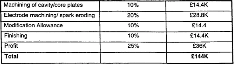
The cost of the fully hardened steel production tool was to be £144K, with a lead time of 16
weeks. Although this appears high, this is because the cost is for a complete mould. In order to
provide a realistic comparison, it is necessary to break down this cost further, to establish the
cost for the core and cavity plates. Table 1 shows the cost breakdown for a typical mould tool.
Activity ~
.. ' ~
Percentage of Cost Actual Cost
Tooling Design 10% £14.4K
Basic Mould Structure (Bolster. 15% £21.6
ejection. machining of cooling
Executive Summary - The Development o/Thermtll Spray Tooling
Machining of cavity/core plates 10% £14.4K
Electrode machining/ spark eroding 20% £28.8K
Modification Allowance 10% £14.4
Finishing 10% £14.4K
Profit 25% £36K
Total £144K
Table 1: Cost breakdown for a typical production injection mould tool
The only costs associated with the core and cavity plates would be the machining operations, the electrode machining and spark erosion time, and the finishing of the core and cavity plates. This would give an overall cost for the core and cavity plates of £57.6K. It should be
remembered, however, that the tool is twin cavity. All of the costs for the low cost tools described are for single cavity tools. The cost for the steel tool should therefore be adjusted accordingly. When doing this, the following assumptions are made:
• Programming and setting will account for around 30% of the machining cost. The programming and setting time will be similar for both single and twin cavity tools. The machining cost for a single cavity tool would therefore approximate to:
0.5(14.4-(0.3x14.4»
+
(0.3x14.4) = £9.36K• The electrode machining and sparking can be assumed to be 50%, as the number of
-electrodes required would be halved (-electrodes would have to be 'mirrored' for left and right hand components) - this would give a cost of £14.4K
• Finishing of the single cavity would be 50% of the cost of the twin cavity, giving a cost of £7.2K.
• Profit is assumed to be added to the overall total i.e. it does not enter into this costing. Using the above assumptions, this would give an overall cost for the steel core and cavity plates of:
9.36
+
14.4+
7.2=
£30.96KAn in-house quotation was generated for the machining of aluminium core and cavity plates. These could be more easily machined, and would not require sparking or polishing, as the
[image:19.546.74.487.58.175.2]Executive Summary -Tile Developmellt oj The mill I Spray ToolillK
A core and cavity set was generated using 'conventional' thermal spraying, that is a thin layer
of kirksite backed with a filled epoxy resin. The overall cost of the set was £6.7K, with a lead
time of 3 weeks.
Finally, a core and cavity set was generated using the Sprayform (Sprayforming Developments
Ltd) process described in Section 2.2. As with the other thermal spray tooling, the cost of the
core and cavity plates is incomplete. In this case, the raw cost of the plates was £6.4K.
However, the plates required finish machining operations, to allow them to be fitted into the
bolster. This added a further £1.5K to the cost, and I week to the lead time.
Table 2 shows the results of the cost comparison, along with the lead times for each
technique.
Tooling type Cost lead Time
Steel Production Tool (P20) £30.96K 16 weeks
Machined Aluminium £11.BK B weeks
Thermal Sprayed Kirksite £6.7K 3 weeks
Sprayformed steel £7.9K 4 weeks
Table 2: Adjusted Costs of Various Tooling Manufacturing Routes
When the relative costs are viewed graphically, the results are as shown in Figure 2.
35
30
25
20
15
10
5
0
Machined Steel
Machined Aluminium
[] Cost (£K)
• Lead time (weeks)
Sprayed Kirksite
Sprayform
[image:20.549.106.473.342.447.2] [image:20.549.134.459.515.757.2]Executive Summary - The Development of Thermal Spray Tooling
Figure 2: Relative costs and lead times for tooling using different manufacturing routes
Executive Summary - The Development of Thennal Spray Tooling
3.0 Physical Performance of Thermal Spray Tooling
3.1 Background
This project provides a detailed examination of the physical properties of thermal spray surfaces; particular attention is paid to those properties of thermal spray surfaces which will affect their performance in a moulding environment. In addition, the project takes an
innovative approach to the production of tooling shells. Part of the programme examines the development of a route for the' production of tooling shells using HVOF (High Velocity Oxy-Fuel) spraying. There is currently no proven route for the production of HVOF shells, and the use of this system involves development of new pattern materials, release agents, and spraying techniques. It is believed that this work is somewhat unique - there is currently no published evidence to suggest that HVOF is being used as a method for tooling shell production. The experimental programme aimed to improve the physical properties of thermal spray tooling; this encompassed a number of novel factors, which are summarised below:
• The development of a completely new method for the production of tooling surfaces, which aimed to provide a significant improvement in the performance of thermal spray tooling. • The improvement of existing thermal spray tooling through post-treatment of the metal
surface - this also aimed to provide a substantial improvement in the performance of existing thermal spray tooling.
• A broad investigation of the physical properties of thermal spray tooling faces, which aimed to establish comparative performance between thermal spray tooling and other
'competitor' technologies.
The whole of the programme carried out in the following paragraphs was carried out as part of the portfolio. Some of the elements, such as ceramic pattern manufacture and some post-treatment work was carried out externally. However, all the assessment of pattern materials, thermal spray shells and post-treatments was carried out at the University of Warwick by myself. More detailed information is available in the portfolio document "Physical Performance of Thermal Spray Tooling".
3.2 Pattern Materials
Executive Summary - The Development a/Thermal Spray Tooling
and the ability to release the tool from the pattern. Many materials have been used as master patterns, with varying degrees of success. The intention of this programme was to determine suitable pattern materials, particularly for the spraying of materials using HVOF, for which there was previously no readily useable pattern material.
It would appear that the choice of master pattern material has a profound effect on the success of depositing sprayed layers, particularly in the case of HVOF sprayed materials. Spraying layers of materials such as zinc and T204M using arc spraying presents little difficulty; the comparatively low melting points of these materials, combined with their relative softness and low particle velocity, means that a wide variety of pattern materials may be used. In the case of HVOF, however, the particle velocities associated with the process are considerably higher. In addition, the substrate temperatures imparted during the spraying process are considerably higher than with arc spraying. This means that the majority of pattern materials which have been traditionally used for arc spraying of low T M materials will be unsuitable for use with
HVOF. In order to provide a suitable pattern material for spraying of such materials, it is
there~ore necessary to take a fresh approach to the materials and processing aspects of pattern production.
Executive Summary - The Development o/Thermal Spray Tooling
this, it would be worthwhile to test several different grades of graphite, as only limited trials were carried out on a single type of graphite.
In terms of ceramic materials, it would appear that any potential substrate must be fired,in order to withstand the particle velocities associated with HVOF spraying. Freeze-cast alumina samples were sprayed in an unfired state, using Diamalloy 1003. The surface suffered
significant degradation, with the steel particles abrading away the surface layer. Firing improves the surface cohesion of the ceramic; however, it also increases the overall
mechanical strength of the material; a range of firing temperatures were tested, in order to find the optimum balance between abrasion resistance and mechanical strength. Although the firing temperature of the freeze-cast samples was optimised for the spraying of Diamalloy 1003, the firing temperature of 10500C meant that the ceramic pattern became difficult to remove using mechanical force. The increased mechanical strength introduced by firing at the higher temperature, would introduce a risk of damage to the tool shell during removal of the pattern. Although the use of alumina as a pattern material for spraying HVOF materials was successful enough for the production of test pieces, it would require further development for the repeatable production of tool shells.
The success of the alumina material is probably due to the fact that there is a strong
mechanical bond between the HVOF sprayed material, and the surface of the ceramic. This is due to the high particle velocities; similar tests conducted with arc spray materials such as 0.8% carbon steels did not yield a cohesive sprayed layer. Although the thermal stresses are as high with HVOF particles, the higher velocity leads to a higher impact velocity at the surface, causing a higher degree of compaction. This suggests that it is only necessary to have a hardened surface layer on the ceramic pattern. This would allow a layer of material to be deposited, but would also allow relatively simple removal of the master pattern, due to the lower mechanical strength of the ceramic. This would reduce the risk of damage to the tool surface, and would also reduce the treatment requirements for the pattern material. This surface hardening could take the form of a flame or laser treatment, which would cause a thin layer of the surface to be locally hardened 1.
1. Subsequent work on the Spraymould programme at the University of Warwick has demonstrated the benefit of localised hardening on
Executive Sununary· The Development of Thermal Spray Tooling
Another viable solution to the problem of pattern removal would be through chemical attack. This is common enough in the casting industry, where ceramic cores are leached out using chemical attack (potassium hydroxide is most commonly used) to remove them from cast parts. Although freeze-cast alumina can be removed in this manner, there are other ceramic materials, such as silicates, which may be freeze cast with similar accuracies, and may be fired to produce similar surface hardness, but are more readily removed using a solvent such as caustic soda. This would mean that the pattern need not be subject to mechanical force, and would thus mean that the risk of damage to the tool face would be reduced.
The approach of selectively hardening the surface layer of a ceramic pattern may solve the problem of removing the bulk of the pattern on completion of the tooling; however, it still leaves the requirement for the breaking of the mechanical bond between the sprayed layer and the ceramic substrate. One possible solution to this would be to integrate a release agent into
the surface of the pattern. Early trials with boron nitride, when painted on as a suspension,
yielded little benefit in terms of release - the material was simply blown away from the ceramic surface, due to the force of the HVOF jet. An alternative approach would be to cast a surface release coat of boron nitride into the alumina pattern, which could then be fired in the conventional manner. This would mean that the boron nitride was an integral part of the
.~
alumina pattern, and would not be removed on spraying. Trials would need to be carried out to establish the required density of boron nitride in the surface layer, to obtain a balance between coating adhesion and release.
3.3 Tensile Properties
The aim of these sets of experiments was to quantify some of the important mechanical properties of thermal spray materials. The principal aim was to determine the effect of the spraying conditions and thermal effects, on the mechanical integrity of various materials. In order to do this, several trials were carried out - tensile testing, flexural testing, and an experiment to determine the effects of thermal cycling on the material strength.
3.3.1 Tensile Strength
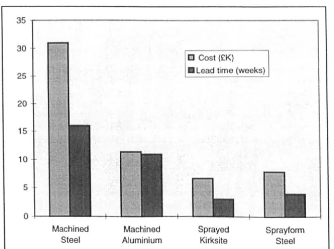
Executive Summary -The Developmellt of Thermal Spray Toolilll!
similarly improved for use in tooling surfaces. Samples of various materials were tested on the
Lloyd tensile tester, as shown in Figure 3. The machine uses a 5kN load cell, and has a
variable cross-head speed. For these purposes, a uniform cross-head speed of I mm/min was
selected. Each material and post-treatment combination was tested 5 times, to give an average
result. When the specimens broke, the cross-sectional area was measured at the fracture point,
allowing the true stress at fracture to be determined by calculating load/cross sectional area.
The graph generated by the machine also allowed examination of the failure mechanism of
each material.
Figure 3: Machine used for tensile & flexural testing
The results showed a clear improvement in the performance of zinc when arc sprayed with
nitrogen as a carrier gas. The failure stress of the tensile test specimens increased by an
average of 12% over air-sprayed zinc. This would indicate that under air-sprayed conditions,
[image:26.551.149.427.229.596.2]Executive Summary -The Developmellt o/Thermal Spray To(}lill~
on the molten particles. Use of the inert carrier gas inhibits the oxidation level, improving the
mechanical properties of the zinc. These results are summarised in Table 3.
Sample Number Zinc (air carrier gas) Zinc (nitrogen carrier T204M (air carrier gas) T204M (nitrogen
gas) carrier gas)
Failure Stress (MPa)
1 0.36 0.41 0.54 0.54
2 0.36 0.42 0.53 0.54
3 0.36 0.42 0.55 0.54
4 0.36 0.42 0.52 0.54
5 0.35 0.39 0.52 0.54
AVERAGE 0.36 0.41 0.53 0.54
Table 3: Effects of Inert Carrier Gas on Tensile Strength
In the case of Tafa T204M, the only change which was noticeable was that the samples arc
sprayed with nitrogen as a carrier gas exhibited more uniformity in their tensile properties; the
actual average failure stress only increases by 2%. This would seem to suggest that T204M is
not uniformly affected by oxidation during spraying, to the same degree as pure zinc. The
material is a kirksite-type material specifically developed for tooling applications, and it may
be that certain alloying elements within the material inhibit oxidation. The results also suggest
that the inconsistencies with air-sprayed T204M may be due to localised oxidation which
causes small inclusions in the sprayed layer, which may cause crack propagation under stress
-the use of nitrogen appears to remove any inconsistencies within -the sprayed layer.
The results for the HVOF sprayed Diamalloy 1003 were extremely significant, as they showed
that the failure stress was lower than expected. Diamalloy 1003 is a stainless steel coating
supplied by Sulzer-Metco in powder form, specifically for HVOF spraying. The coating is
relatively low cost, but produces a hard, dense coating, making it an ideal coating for tool
surfaces. The HYOF sprayed tensile test samples were only approximately 0.6mm thick,
whilst the arc sprayed samples were around 2mm thick. Although the failure stress of the
Diamalloy 1003 was much higher than the arc sprayed materials, the maximum failure loads
were somewhat similar between arc spray and HYOF. It had been anticipated that HVOF
would provide significant benefits in tensile properties, allowing a thinner sprayed shell to be
used, as opposed to a thicker, weaker arc spray shell. The results, however, indicate that use of
[image:27.552.60.508.101.274.2]Executive Summary - The Development o/Thermal Spray Tooling
more prone to cracking under stress. The lower failure load of the HVOF samples may be in part due to the process parameters used, and may also be due to the spraying conditions. In normal spraying, HVOF coatings are applied to substrates which are heated to around 150-200°C. The fact that these samples were sprayed onto cold samples may cause thermal shock in the sprayed coating. In addition, the coatings were sprayed using propane as the combustion gas. This is now known to produce inferior quality coatings, due to the variability of the propane supply [19]. Propylene is now the recommended choice of combustion gas, due to its more consistent quality of supply. Both of the above factors may have affected the quality of the HVOF samples. However, based on the above results, a coating thickness of above 0.95mm would provide significant benefits over arc sprayed coatings, although the shell cost would be somewhat higher.
3.3.2 Flexural Strength
The purpose of this experiment was to determine the effect of different carrier gases on the flexural strength of thermal spray materials. Although tensile strength is an important test of a material's mechanical properties, flexural strength is more indicative of the type of stress which will be encountered in moulding environments. Zinc was tested, with air and nitrogen as carrier gases. This was done in order to assess the effects of reduced oxidation on the failure mode of the material. This experiment used the Lloyds tensile test machine, as shown in Figure 3. The machine was set up to perform a compression test, with a cross-head speed of
Executive Summary -The Development a/Thermal Spray Tooling
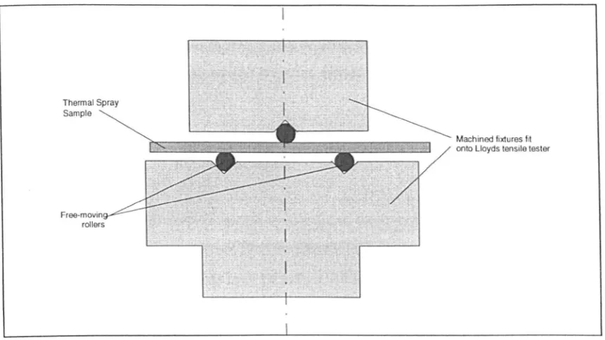
in Figure 4. The samples were placed with the 'tool' face downwards in the fixture.
Thermal Spray Sample
Free·movin rollers
Machined fixtures fit
onto Lloyds tensile tester
Figure 4 : Flexural testing fixture
The results showed that the choice of carrier gas had a considerable effect on the flexural
properties of arc sprayed zinc. When air was used as a carrier gas, the overall flexural strength
appeared to be higher, but the material was more susceptible to brittle failure. With nitrogen
as a carrier gas, the overall failure load was reduced slightly, but the material appeared to be
more ductile -this is demonstrated by the higher displacement before fracture, and the overall
area of the load/displacement curve.
The experiment showed that the choice of carrier gas had a profound effect on the Modulus of
Elasticity of the zinc. This is important, as the Modulus of Elasticity (E) will determine the
way in which a material behaves under loads. The modulus of zinc with air as a carrier gas
(lO.37GPa) is more than twice that of the nitrogen-sprayed samples (4.86GPa). In addition, as
would be expected, the elongation to failure of the inert sprayed samples is far higher than for
the air-sprayed sample. In application terms the higher oxide content associated with the
air-sprayed samples gives a higher stiffness but significantly reduced ductility. These figures are
extremely low, when compared to the figures for wrought materials. For example, the E of
[image:29.546.54.485.81.323.2]ExeCLIlive Summary -The Deve/opmelll11Therlllal Spray Toolin!;
similar to wood, with an E of 11-14GPa, or nylon, with 2.1-2.8GPa. As with many of the
other properties of sprayed materials, this is most probably due to the levels of porosity in the
material, and the levels of oxidation. It can be seen that the use of inert carrier gas is beneficial
in improving the ability of the material to flex without damage, but also reduces the overall
failure stress of the material.
3.3.3 Thermal Fatigue
This set of experiments was designed to determine the overall effect of thermal cycling on the
mechanical strength of a material. Previous work [28] showed that under rotational moulding
conditions, arc sprayed surfaces may be subject to a reduction in their mechanical properties
due to repeated cycling at elevated temperatures. In this benchtop test, the programme
included HVOF sprayed Diamalloy 1003, and arc sprayed zinc and Tafa 204M.
In order to simulate the environment in which the materials would be expected to operate,
they were subjected to 300 cycles from room temperature to 200o
e,
in a bath of low T Malloy.The materials were then removed, and allowed to cool to room temperature. After this, their
tensile strength was tested using the same test conditions as the untreated samples. The results
clearly show that the thermal cycling has an effect on the tensile strength of the materials,
although the results are more pronounced for arc sprayed materials.
In the case of Tafa 204M, the average tensile strength dropped by a considerable amount;
around 23% of the original tensile strength was lost after 200 heat cycles. Whilst the zinc had
a lower initial tensile strength, the loss after heat cycling was only 14%. This would suggest
that both sprayed samples suffered some degree of oxidation, which was exaggerated by the
elevated temperature.
In the case of HVOF sprayed Diamalloy 1003, there is very little reduction in the overall
performance of the material, in terms of mechanical properties. The material only suffered an
average 4% deterioration in tensile strength, after 200 heat cycles. This is to be expected;
stainless steel is specifically oxidation resistant, particularly at comparatively low operating
Executive Slimmary . The Developmellt a/Thermal Spray ToolillR
lower than expected in the initial (untreated) experiment, this may well be due to oxidation
which occurred at the spraying stage. The high temperatures would mean that the spray
particles would be prone to oxidation, which would explain why the samples were more brittle
than expected. However, this experiment shows that steels would not be significantly affected
by thermal fatigue at temperatures such as this. These results are summarised in Table 4.
Sample Zinc Zinc (after 200 T204M T204M (after Oiamalloy 1003 01003 (after Number (untreated) heat cycles) (untreated) 200 heat (untreated) 200 heat
cycles) cycles)
Failure Stress (MPa)
1 0.36 0.31 0.54 0.42 0.86 0.83
2 0.36 0.30 0.53 0.39 0.84 0.82
3 0.36 0.33 0.55 0042 0.83 0.80
4 0.36 0.31 0.52 0040 0.85 0.79
5 0.35 0.32 0.52 0040 0.83 0.81
AVERAGE 0.36 0.31 0.53 0.41 0.84 0.81
Table 4: Effect of Thermal Fatigue on Tensile Strength
3.4 Wear Resistance
The intention behind this set of experiments, was to provide comparative wear data, showing
the effects of a standard abrador on various materials and post treatments. Although not
strictly representing in-mould performance, this would give an idea of how each material
would perform under the same conditions. Several thermal spray materials and
post-treatments were tested. In order to provide a benchmark, other 'low cost' tooling materials
were also tested. A rig was constructed as shown in Figure 5 for the purpose of providing
consistent wear test data. In order to provide accelerated wear conditions, the wear test
samples were moved in a reciprocal motion against a sheet of 400 grit wet & dry paper. The
tests were conducted without any lubricant; in order to prevent damage to the abrasive sheet, it
was indexed after every 10 cycles - a linear actuator being used to move the sheet along 1 axis
after a set number of cycles. Another important aspect of the indexing was to maintain a
constant level of abrasion. The height the sample was measured before testing, and the rig was
then programmed to carry out 500 cycles, at a constant rate of 2 strokes per second, with a
constant load of 2kg on the sample. Readings were taken at 50 cycles, then 100, 200, 300, 400
and 500 cycles, to determine the levels of wear at each stage. At the end of 500 cycles, the
[image:31.551.60.512.167.321.2]ExeCUlive SlImmary - The Deve/opmelll o/ThermaL Spray Too/illK
Support
Variable weight
Abrasive Sheet Clamp
[image:32.548.52.522.65.262.2]Base Plate
Figure 5 : Wear test rig
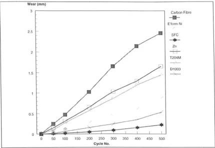
It was clearly shown that there was a wide variation between the wear resistance of thermal
sprayed materials in an untreated state, particularly when compared with the 'benchmark'
materials, electroformed nickel and carbon fibre composite, two materials commonly used for
aerospace tooling. Out of all the materials tested, the carbon fibre showed the poorest abrasive
resistance -this reflects many of the durability problems associated with tooling made from
this material; as it is relatively soft, it is prone to abrasion and damage in the moulding
environment. Pure zinc sprayed with air as a carrier gas showed an improvement of 33% in
abrasion resistance compared with carbon fibre, although its performance was relatively poor
in comparison to other materials. Surprisingly, the T204M did not show significantly better
wear resistance than zinc, despite the fact that it is specially formulated to improve wear
resistance. The HVOF material performed well in the abrasion tests, with Diamalloy 1003
improving abrasion resistance by 42% compared to electroformed nickel, and a 68%
improvement over zinc. The hardness of the material, coupled with the fact that the surface is
extremely dense, mean that the material is far more wear-resistant compared to arc sprayed
surfaces. This implies that a thin shell of HVOF-applied steel could be used to the same effect
as a much thicker arc sprayed layer of material. All of the above results are summarised in
ExeclIIive Summary -The Deve!opment lifT/len/iii! Spray Tooling
Wear (mm)
3 , - - - ,
2.5
2
1.5
0.5
o 50 100 150 200 250 300 350 400 450 500 Cycle No.
Carbon Fibre
---E'form Ni/ SFC
-.-Zn
--!::l-T204M - ,
-Dl003
,
--Figure 6: Comparative wear results for various materials
The best performer in this group of untreated samples was the martensitic steel deposited by
Stress Free Coating (i.e. deposited by the Sprayform process, as described in Section 2.2). The
material is obviously extremely hard, and therefore abrasion resistant. Although the material
performed better than HVOF coatings in this test, the coating is extremely porous, due to the
spraying parameters which are used. The abrasion test is more suited to testing the hardness of
materials, rather than their resistance to abrasion during moulding. It may be that the more
porous materials do not perform to the same level in a moulding environment, as molten
plastic may be able to enter the porosity, and remove localised areas. In order to provide a
fuller assessment of the wear performance of thermal spray surfaces, it would be necessary to
make a number of tools, each using a different material. Although this would provide a more
accurate picture of the wear performance, it would be difficult to extract quantitative data.
Although empirical, this set of tests at least provides comparative data for the materials,
without the expense of a mould trial programme,
3.5 Vacuum Integrity
One important application of thermal spray tooling will be for vacuum forming of composites,
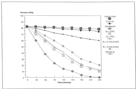
[image:33.548.56.487.60.356.2]Executive Summary - The Development a/Thermal Spray Tooling
behind this set of experiments was to test the ability of thermal spray surfaces to hold a vacuum over a period of time - a critical attribute for this type of tooling. Various sprayed materials were tested, along with post-treatments and benchmark materials. The materials were tested using the actual vacuum bagging technique which would be used in production moulding.
The results of these experiments were interesting, as they clearly showed the difference in vacuum integrity between arc sprayed and HVOF sprayed materials. In addition, it is possible to assess tests concentrated on comparing the 'benchmark' materials, electroformed nickel and carbon fibre composite, with untreated thermal spray samples. Over the 4 hour test period, both benchmark materials performed well. In both cases, a slight loss of vacuum was evident. As both materials are relatively dense, this may indicate a slight leakage of air into the
vacuum system - however, this did not affect the overall integrity of these materials. By comparison, unbacked, untreated thermal spray samples performed poorly. In the case of both arc spray materials, zinc and Tafa 204M, the vacuum loss after 4 hours was 100%. The porous nature of the materials is clearly unsuited to use for vacuum purposes in their untreated state. The untreated Diamalloy 1003 performed better than arc spray materials, but also suffered a vacuum loss of 52%. Although this would not be suitable for autoclave applications, the thickness of the material may also playa part in the vacuum integrity. In the case of this test, the HVOF sample was 0.6mm thick, compared to the arc spray material thickness of 2mm. Thus the HVOF material displayed a marked improvement over the arc spray samples despite being less than a third of the thickness. Figure 7 shows the results for zinc sprayed samples, with various post treatments, including PTFE, Poly-FIuoro Alkyl and HVOF-sprayed
Vacuum (-kPa) 100 90 80 70 60 50 40 30 20 10 0
0 30 60 90 120
Time (minutes)
ExeCl/tive SUlllmary -The Development o/Thermal Spray ToolinK
150 180 210 240
Carbon Fibre
-II-E'formNi
-+-Untreated 111
-¢-111 + PTFE
o
111 + PFA
-V-111+0.1rrm01003
111 + 0.2rrm 01003
-0
-Backed 111
Figure 7: Loss of vacuum vs. time for thermal spray samples & benchmark materials
3.5.1 Effects of Post-Treatment
In terms of the post-treatments which were applied to the arc sprayed surfaces, the results
were somewhat disappointing. Both zinc and T204M were treated with PTFE, and also with
PFA. These coatings were applied on the recommendation of Poetons, as the optimal coatings
for the material type and anticipated operating conditions of the tooling surfaces. The effect of
the coatings on improving vacuum integrity was minimal; this would suggest that the porosity
levels within the arc sprayed coatings are so high, that it was impossible for the post
-treatments to totally in-fill all surface porosity. Although the coatings had little effect on
vacuum integrity, they may well prove extremely invaluable as release coats; however, it
would appear that their use as vacuum sealing coats is limited.
The problems with the polymeric post-treatments is borne out to SOme extent by the results of
treating zinc and T204M with a thin layer of Diamalloy 1003. However, this thin layer did
have some effect on the overall vacuum integrity. This may be because the steel particles
actually alter the physical profile of the arc sprayed surface on impact. The harder HVOF
[image:35.548.67.504.55.340.2]Executive Summary - The Development of Thermal Spray Tooling
compared to the zinc. This may explain why there was some slight improvement in vacuum integrity when compared with the polymeric post-treatments. This initial test was carried out with a O.lmm layer of Diamalloy 1003. A second test with a 0.2mm layer of the same material produced a considerable improvement in vacuum integrity. This would suggest that the· thicker the layer of HVOF material, the higher the vacuum integrity. This is to be expected; the HVOF layer will have a considerably lower level of porosity, and will allow less leakage.
3.5.2 Effects of Backing Material
The addition of a backing material to all of the thermal spray samples provided a considerable improvement to the vacuum integrity of the samples. The samples had an CY 149 aluminium-filled epoxy backing added, which gave a total sample thickness of Smm. The results clearly showed that the backed samples provided approximately 80% improvement in vacuum integrity over the test period. This suggests that the vast majority of leakage was through the thermal spray sample, and that addition of a backing material reduces leakage to a large
degree. However, the backed samples still did not perform as well as the benchmark materials. One possible cause of this was that the porosity of the thermal spray layer allowed ingress of air under the vacuum tape - the average levels of porosity in arc sprayed samples would not preclude this. To test this assumption another experiment was performed, to determine the level of 'side leakage' which occurs through the thermal spray sample.
3.5.3 Elimination of Side Leakage
Executive SUIIII/lQlY -The Development o/Thermal Spray ToolinK
E><Ira barriers 01 vacuum tape
to determine level of side leakage
Smm (TYP)
[image:37.546.55.484.57.374.2]Pipe to vacuum pump
Figure 8: Positioning of extra vacuum tape layers
The results clearly showed that there was some vacuum loss due to side leakage, which
occurred in the area ofJhermal spray directly under the first layer of vacuum tape. The loss
then rapidly fell away, and at a distance of 50mm from the inside of the first vacuum tape
layer, became relatively constant. This would suggest that the porosity of the thermal spray
surface external to the vacuum environment is also important in determining vacuum
integrity. Post treatment could possibly reduce the porosity of this external area -a more
comprehensive solution would be to mount a second layer of vacuum tape, approximately
35mm from the first -this would contain the vast majority of the leakage. These results are
Execlltive SUllllllary -Tile Developlllent of Therlllal Spray ToolinK
Vacuum (-kPa)
100 Carbon Fibre
---90 E'form Ni
-+-Untreated Zn80
-+-70
Backed Zn (1 layer vac
LJ
60
Backed Zn (2 layers vac tape)
+
___ .J Backed Zn §tyers vac tape) 50
40
30
20
10
0
0 30 60 90 120 150 180 210 240
[image:38.550.72.500.59.323.2]Time (minutes)
Figure 9: Effect of 'side leakage' on vacuum integrity of zinc samples
3.5.4 HVOF Material Thickness
Some of the results were used to determine the thickness of Diamalloy 1003 which would provide full vacuum integrity, without any backing material. In the case of zinc, thin coats of
Diamalloy 1003 were applied to the surface, to see what effect they had on the vacuum
integrity of the overall shell.
The results showed that as the material thickness increased, the vacuum integrity improved,
and that this relationship is linear. The minimum material thickness for holding complete
vacuum integrity was around IArnm. However, backing the thermal spray surface has already
been shown to have a profound effect on the vacuum performance -the minimum backed
HVOF material thickness for holding vacuum is around O.8mrn. In a tooling situation, it
would therefore be necessary to spray a layer of HVOF material to around 0.8mm thickness,
and then back it with a carbon fibre composite material to provide complete vacuum integrity.
It may be possible to reduce the thickness of the HVOF layer still further by the provision of
Executive Summary - The Development a/Thermal Spray Tooling
4.0 Compression Moulding Project
4.1 Background
The compression moulding project was important for Rover Group, as it proved the ability of thermal spray tooling, as a method for the production of large prototype tools for the
production of 'technical prototype' components. These are components which are
manufactured in the correct engineering material, which may then be used for testing and evaluation. In this case, the required components were an important part of the vehicle structure (details of the components may not be released for reasons of confidentiality). The selected method of manufacture for these components was compression moulding, using a GMT (Glass Mat Thermoplastic) material.
In selecting an appropriate material for the components, a number of materials were evaluated. including SMC (Sheet Moulding Compound), and GMT (Glass Mat Thermoplastic). GMT was determined to be more desirable, as it was polypropylene-based, and thus more recyclable than the thermoset SMC - SMC components of this type had also been manufactured. In addition, Rover Group had no previous experience of producing this type of components in GMT - their current experience of GMT moulding is limited to battery boxes. It was thus deemed important to evaluate the effectiveness of using GMT as a potential material. Compared with aluminium, GMT offered the following advantages:
• Cheaper and more readily recyclable than aluminium.
• The possibility of producing a one-piece moulding; the current aluminium assembly consists of a number of individual pressings.
• Greater accuracy of part - improved dimensional repeatability due to absence of component springback, as seen with pressed aluminium/steel components
• No requirement for painting • Lower part cost
Although the GMT component was calculated to have a lower stiffness than existing steel or aluminium assemblies, which are traditionally used in a monocoque construction, this was not deemed to be a major disadvantage, as the GMT assembly would be fully supported by an
Executive Summary - The Development of Thermal Spray Tooling
the use of a single piece, pressed aluminium component. The assembly would therefore consist of a number of joined sections, increasing complexity, weight and cost. Although the ultimate aim is a single component, the initial design consisted of a five-piece assembly. In order to manufacture these components, it was necessary to produce a set of tooling capable of moulding approximately 30 component assemblies in GMT, using the compression
moulding process. Although the use of thermal spraying is widespread as a route for prototype tooling, there is no literature to suggest that the technique has been previously used for
compression moulding of GMT, and certainly not for components the size of the components required (up to approximately 4m2). However, research has been carried out, notably at the
Advanced Technology Centre, into the performance of a range of tooling methods, including thermal sprayed surfaces, for the compression moulding of GMT [23]. This work took
samples of various materials, including thermal spray materials, and subjected them to tests to establish the wear resistance under benchtop test conditions, and also under moulding
conditions. Based on the results of these tests, it was decided that Tafa 204M would be an appropriate material to use for the thermal sprayed tool shell, in order to provide good surface wear resistance. However, as this material is expensive, it was decided that a thin surface layer (-lmm) ofT204M would be backed up with a thicker layer (-2mm) of pure zinc, a
considerably cheaper material. Thus the tool surface would retain good wear resistance, whilst keeping cost as low as possible.
In terms of the backing material for the tooling, it was critical that an appropriate material was selected, given the particular nature of the moulding process. During moulding, the tools are maintained at a constant temperature of around 80°C. The GMT is heated to around 250°C, and placed in the mould, which is then closed under pressure - this may be up to 450kg/cm2• The material then flows to fill the mould, which will subject the mould to a hydrostatic pressure of around 150kg/cm2• The tooling is thus subject to considerable compressive and
shear stresses. The backing material must thus be capable of withstanding these forces without damage. The normal backing material for thermal spray shells is an aluminium-filled epoxy resin, which is post-treated to 150°C to encourage cross-linking and improve strength.