Sander Köllmann Bachelor Thesis University of Twente
Industrial Engineering and Management
Company X supervisor Supervisor: Mr. X
University of Twente Supervisor 1: Dr. P.C. Schuur Supervisor 2: Ir. H. Kroon
ANONYMOUS VERSION
i
MANAGEMENT SUMMARY
This thesis is the closing element of my Bachelor Industrial Engineering and Management at the University of Twente in Enschede. It is performed at company X in the south of the Netherlands. The target is to describe, analyze and improve a specific part of the company X logistics system, i.e., airfreight of inbound logistics.
Company X is a car manufacturer with its assembly plants all around the world. Car parts are produced in supplier plants all over the world and are shipped to these plants for final car
assembly. This process is called “inbound logistics”.
The critical element in Company X’s car manufacturing process is continuity. Assembly line stoppages are very expensive and must be avoided at all times. 2018 will be a critical year for Company X, as it must reach mass production volumes, fulfill the financial market expectations and stay ahead of competition. Therefore, all efforts are focused on timely delivery of parts to the assembly lines.
Inbound logistics overseas can be done by boat, in containers or by plane, in ULDs. ULD is short for Unit Loading Devise. A ULD is an aluminum container used to store boxes/pallets during flight. These ULDs have an efficient fit in the aircraft and allow for easy handling. Obviously, container shipments are cheaper, but also slower, requiring longer term planning. For short term needs or unforeseen events, car parts are flown in, using boxes that are packed in ULDs. In order to minimize the high airfreight cost, this study focuses on improving the use of ULDs by designing a more efficient stacking pattern of standard boxes, the so-called IMCs.
To improve the load efficiency of the ULDs a cargo layout model has been designed. This model calculates an efficient filling method on the basis of the size of ULD and IMCs used. This limits the cost per volume shipped. The model can be used by the handlers when loading the ULDs or by the freight forwarders in order to create pre-stacked pallets ready for ULD loading. The benefits of pre-stacking pallets for maximum ULD efficiency are less handling, more load stability and therefore less risk for transport damages and unforeseen delays. The benefit for the freight handlers is a higher ULD filling grade, thus decreasing freight cost per m3.
In conclusion: using the Cargo Layout Model improves the reliability, predictability and efficiency of the inbound logistics process for Company X, decreasing the risk of faulty deliveries and ultimately line stoppages.
ii
PREFACE
Before you lies the thesis “Cargo Layout Design for the Stackability of Boxes in ULDs for the Inbound Products of Company X”. This thesis is written as a final stage of my Bachelor Industrial Engineering & Management at the University of Twente. I conducted the research as an intern at Company X in the south of the Netherlands. The main research question is formulated together with my University of Twente supervisor, Dr. P.C. Schuur.
During this period as an intern at Company X, I have learned a lot about the company, their way of management and the ‘hands-on mentality’. In addition, it has been a very fun time thanks to the friendly and open environment and all colleagues.
Writing the thesis and designing the Cargo Layout Model have been challenging and educational at the same time. Fortunately, my supervisors have been available throughout this period to answer all my questions and help improving the research.
I would like to express my sincere gratitude to company supervisor Mr. X, for giving me the opportunity to conduct my research at Company X, guiding me throughout the entire internship and making the four months at Company X great for me.
In addition, I would like to thank my University of Twente first supervisor Dr. P.C. Schuur for helping me take this thesis to a higher level, providing me with new insights to design the model and improving the thesis. Furthermore, I would like thank Ir. H. Kroon for his insights and support as my University of Twente second supervisor.
iii Table of Contents
Management Summary ...i
Preface ... ii
1. INTRODUCTION ... 1
1.1 Introduction to Company X ... 1
1.1.1 Company background ... 1
1.1.2 Logistical elements explained ... 3
1.2 research Problem ... 8
1.2.1 Context ... 8
1.2.2 Current situation of logistics inbound EMEA ... 9
1.2.3 Desired situation ... 11
1.2.4 Discrepancy between current and desired situation... 11
1.2.5 Problem owners ... 12
1.2.6 Research goal ... 12
1.2.7 Research question and design ... 12
1.3 Research design ... 14
1.3.1 scope ... 14
1.3.2 deliverables ... 14
1.3.3 limitations ... 15
1.3.4 thesis structure ... 15
2. current airfreight Practice at Company X ... 17
2.1 The current process ... 17
2.2 quantification of the current airfreight use by Company X ... 18
2.2.1 How efficient is the current ULD filling method? ... 18
2.2.2 How much does airfreight cost Company X Annually? ... 18
2.2.3 How many boxes (IMC units) are transported via airfreight annually? ... 18
2.2.4 How many cubic meters are used for Company X’s airfreight annually? ... 18
2.2.5 Estimated efficiency of current airfreight use ... 19
2.3 THe pricing of airfreighted goods ... 19
2.4 Pallet usage ... 20
2.5 the condition of the cargo ... 20
2.6 Improvement Options ... 20
3. Theoretical framework ... 21
iv
3.1.1 One-dimensional, two-dimensional and three-dimensional ... 21
3.1.2 Bin-Packing Heuristics ... 22
3.1.3 real-world-like problems and restrictions ... 24
4. Methodology ... 25
4.1 Research methodology ... 25
4.2 Applied Methodology ... 25
4.2.1 Determining the current airfreight situation ... 25
4.2.2 The quantification of the current airfreight use of Company X ... 26
4.2.3 Determining the PRICING of airfreighted goods ... 26
4.2.4 THe obligatory usage of a pallet ... 27
4.2.5 THe effects of stacking IMC units ... 27
5. Efficient cargo layout tool ... 29
5.1 Concept ... 29
5.2 Simplefied problem and phased plan ... 29
5.2.1 Two-dimensional approach for rectangular containers ... 29
5.2.2 three-dimensional approach for rectangular containers ... 30
5.2.3 Three-dimensional approach for containers with a sloped side ... 32
5.2.4 Adding a second orientation ... 34
5.3 Design ... 35
5.3.1 Input ... 35
5.3.2 assumptions ... 36
5.3.3 Output ... 37
5.3.4 Toy Problem ... 39
5.3.5 Tool design and vba macros ... 42
6. Conclusions and recommendations ... 49
6.1 Conclusions ... 49
6.2 Recommendations ... 50
7. Discussion ... 51
References ... 52
Appendix 1 - Aircraft types... 53
Appendix 2 - IMCs ... 55
Appendix 3 - ULDs ... 57
1
1.
INTRODUCTION
In the framework of completing my Bachelor Industrial Engineering & Management at the University of Twente, this thesis is written. I performed research at the Automotive Manufacturer Company X in the south of the Netherlands. The thesis focuses on designing a Cargo Layout Model that calculates an efficient cargo layout for Company X’s inbound EMEA boxes in airfreight.
This chapter contains an introduction to Company X and its inbound logistic process in section 1.1. In section 1.2 the research problem is described followed by the research design in section 1.3.
1.1
INTRODUCTION TO COMPANY X
2 Since Company X is a relatively new and very innovative company, the focus is on global hierarchy. This means that Company X aims for minimal regional divisions and tries to keep the entire organization centralized. Decisions are made by the central management. Since Company X is a multinational, having regional divisions is unavoidable and necessary in order to implement market specific strategies and marketing campaigns. The advantage of having a global centralization is effective global control in all markets. This allows Company X to quickly implement new strategies and tactics.
A downside of a global hierarchy is that, if Company X needs to respond in a specific market, there is no local management. This can only be solved by giving local offices more autonomy
but this ‘decentralization’ is something Company X is trying to avoid. Company X keeps this global hierarchy in order to continuously adapt to new market expectations and being more innovative. Below, Company X’ chain of command is shown in figure 1-2. Figure 1-3 shows Company X its factory and figure 1-4 shows the outline and layout of Company X’s factory.
Figure 1-1: Company X’ Chain of Command
3 1.1.2 LOGISTICAL ELEMENTS EXPLAINED
Inbound logistics for Company X EMEA
This research focusses on the inbound logistics of Company X EMEA. EMEA stands for Europe, Middle-East and Africa. “Inbound logistics refers to the transport, storage and delivery of goods coming into a business. (Outbound Vs. Inbound Logistics, 2017)” In the case of this research thesis, the inbound logistics of Company X refer to the products transported from and within EMEA. This means that the transport of products from EMEA to the factories in the USA is also arranged by the Logistics team EMEA & India. In figure 1-5 below, a map is shown with all suppliers that are handled by the logistics team EMEA.
Figure 1-5: EMEA Inbound Suppliers Company X
4 Air freight is the most expensive method of transportation in the cargo business and used mainly for urgent and high-value items. There are restrictions on the weight and size of the goods that can be carried, as well as more banned items. Packaging is very important since size affects price. (Air Freight Guide, 2017). Since airfreight has far more transportation restrictions than container shipment, it is harder to respond to last minute changes and still arrange efficient transportation. One of the major restrictions for Company X is the height in the planes. As for different aircrafts, Company X uses three options.
- Freighter Aircrafts - Wide-body Aircrafts - Narrow-body Aircrafts
More details of these planes can be found in appendix 2.
Due to size restrictions and availability, almost all airfreight of Company X is done using wide-body aircrafts.
Unit Load Device (ULD)
To make sure cargo is being loaded and carried in an efficient way, large aircrafts use specific
pallets and containers known as Unit Load Devices (ULD). “A Unit Load Device is either an aircraft pallet and pallet net combination, or an aircraft container (Unit Load Devices (ULD), 2017).” The ULDs are mostly handled by freight handlers and are therefore not filled by forwarders. (Unit Load Devices (ULD), 2017).
Since most of the airplanes used by Company X are Boeings, an article will be used of Boeing as a reference for ULDs. Boeing has a total of thirty different ULDs used in their aircrafts, each
with their own specifications and ‘common designation’. In total, there are about 900,000
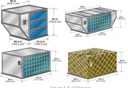
[image:10.595.163.408.584.752.2]aircraft ULDs in circulation with a total value of over USD $1 Billion (Unit Load Devices (ULD), 2017). Since they require correct handling, the International Air Transport Association (IATA) started an ULD safety campaign with five key points regarding the use and handling of ULDs. There are four types of ULDs that fit in a wide-body aircraft. There are rectangular ULDs and ULDs with (a) sloped side(s). A ULD consists of aluminum, aluminum with canvas, or an aluminum basis that is then wrapped and netted. The ULDs shown in figure 1-6 fit in the lower hold of a wide-body aircraft.
5 The thirty different kinds of ULDs with their corresponding specifications and restrictions are shown in appendix 3. Since only wide-body aircrafts are the focus of this research thesis, a total of 18 ULDs will be implemented in the designed tool. Below in figure 1-7, the common path of an ULD is shown. Boxes are delivered at an airfreight handler warehouse where ULDs are ‘build’.
Several legal/documental steps are performed so that the products are approved for transport. The handler moves the ULDs to the designated flight and the products are then transported.
On arrival the ULDs are ‘broken down’, picked up by a freight forwarder and moved to the final destination.
ISO-Modular Carton (IMC) Program
In order to make sure that the inbound products of Company X get transported correctly by their suppliers, Company X offers standard packaging options from where suppliers choose a certain packaging option called the ISO-Modular Carton (IMC) program. This IMC program is an industry standard for ocean freight. The IMC program was created by FORD in order to arrange a standardized packaging system for their suppliers (Iso Modular Carton, 2017). This program is optimized for transportation and Company X made their own IMC program for their products.
Depending on the size of the part needed to be transported, an IMC-option gets picked. These options vary, depending on continent of import and overseas. The two groups consist of the
‘North & South America IMC Carton Sizes and Performance Specifications’ and the ‘European & Asia Specific Carton Sizes and Performance Specifications’. Since every part has a unique
dimension, the IMC program offers standardized options such that not every product needs a unique package.
Company X has tens of IMC options for North- and South-America, and several tens of options for Europe and Asia. Each IMC option has its own restrictions and dimensions. These are shown in appendix 2.
Container Shipment vs. Airfreight
In this chapter, container shipment is compared to airfreight. In figure 1-8, five aspects of transport are mentioned. The left side means it is better for container shipment, the right side means it performs better in airfreight (International Air Freight Explained: Calculating Costs and Price Trends, 2017). Subsequently, each aspect and their position will be explained.
6 Speed
In general, airfreight is approximately 25 times faster than container shipment. The average speed of a wide-body aircraft ranges up to about 900 km/h while a container ship travels at about 35 km/h. High-priority items that need to arrive at a certain location with a strict
deadline thus often are being transported using airfreight. Standardized items, ordered weeks before demand, are often being transported using shipment since time is of no relevance. Reliability
As a whole, air freight is a more reliable transportation method compared to shipment. There are several reasons for that statement. First of all, shipments tend to be more sensitive to delays due to poor weather conditions or other influential factors. Furthermore, shipments via ocean lines mostly run on weakly schedule compared to daily schedules regarding air freight. Most delays can thus be avoided with airfreight since several flights per day travel in between major cities which is far more often compared to ocean lines.
Cost
Cost is an important aspect for every company. For that reason, airfreight is often avoided since it is far more expensive compared to shipments. Airlines charge their cargo customers according to chargeable weight.
Chargeable weight is mostly described as:
“The Chargeable Weight is the Actual Gross Weight or the Volumetric Weight of the shipment
– whichever is the greater. Typically, large items with a light overall weight take up more space on an aircraft than a small, heavy item. That’s why the Airlines charge according to Chargeable Weight (Chargeable Weights, 2017).”
The price difference between airfreight and container shipment is substantial. Due to cost of transportation, companies tend to move their products for the lowest price while maintaining reliability (International Air Freight Explained: Calculating Costs and Price Trends, 2017). Airfreight is often used for last-minute high priority products or other high value items.
7 Since cost is such an important factor, it will be broken down for the airfreight sector. In general, airlines have three cost components (Modes of transportation and their performance characteristics, 2013).
• The first one is fixed cost of infrastructure and equipment.
• The second component is cost of labor and fuel, independent of passengers or cargo, but fixed for every flight.
• Third and final, a variable cost that depends on the passengers or cargo carried. Due to the fact that most of the costs are already incurred when the aircraft departs, it is of great importance for the airline to maximize the revenue generated per flight and thus arrange efficient cargo layout. Due to these three cost components and the fact that most of the costs are predetermined before takeoff, airfreight is far more expensive compared to container shipments.
CO₂ Emissions
The reduction of CO₂ emissions has become extremely important since the issues of global
warming started to become more apparent and the consequences of using fossil fuels started to arise. Comparing airfreight to container shipment, the conclusion is that boats are far more carbon-efficient than airfreight. As stated in an article about the comparison of emissions:
“A big ship will emit about 0.4 ounces of carbon dioxide to transport 2 tons of cargo 1 mile.
That’s nearly a fiftieth of what an airplane would emit to accomplish the same task (Berg, 2016).
“
This big difference can be a decisive factor for companies reducing their carbon footprint. The downside of the speed of container shipments imply last-minute high-priority items can’t be
transported using airfreight.
Size Restrictions and Weight Restrictions
8
1.2
RESEARCH PROBLEM
This section describes the main problem of this thesis. In section 1.2.1 the context of this thesis is explained, followed by a description of current logistics in 1.2.2. In section 1.2.3 the desired logistical situation is described. Subsequently, in section 1.2.4, the discrepancy between those two situations is mentioned. Then in section 1.2.5 the problem owners are outlined followed by the actual problem definition in section 1.2.6.
1.2.1 CONTEXT
The context for this research consists of two parts.
• First of all, the logistics team EMEA of Company X wants more insight in packaging of inbound suppliers. This is needed for the major goal of automating the lines and factories of Company X’s models. Since many suppliers are non-compliant regarding packaging and labeling, complaints arise at the factories. This is something that needs to be researched and changed. The EMEA team started with a chargeback protocol since the start of the research in combination with the Supplier Operations Support (SOS) team. Since this is a new protocol, the boundaries must be set and this is done during this research thesis.
• Secondly, the company lacks process optimization. As Company X focusses on rapid growth, the company doesn’t optimize the current processes. The optimization of airfreight cargo layout has not been focused on before and thus this will be a major component of this research thesis.
The problem cluster in figure 1-9 shows the relationship between the problems that lead to the current situation.
Figure 1-9: Problem Cluster
❖ ‘Change in part’: This is caused by the continuous improvement of Company X‘s
9
❖ ‘Delay in delivery’: A delay in delivery is something that can always happen do to several circumstances. A suppliers can have production issues, accidents or strikes can cause parts to not be transported in time, etc. A delay in delivery can cause a problem with container shipment since this takes a total of two to five weeks for a shipment to arrive depending on port routes.
The two issues above combined lead to a delay in the part delivery and thus to airfreight instead of container shipment. Airfreight is much faster which is needed to guarantee timely arrival. The downside is that airfreight is much more expensive.
❖ Company X’s rapid growth: Company X is dominating the current market and known as the pioneer of driving. In order to stay ahead of competition, Company X is continuously growing as fast as they can, improving their products and designing new products. If Company X would stop doing this and focus on making optimization of their transportation and production, competitors would have more time to take part in the market as well which leads to more competitors in the market. Another aspect is the value of Company X compared to other automotive companies. Earlier this year, Company X became more valuable than Company Y.
Figure 1-10 shows the comparison between the car companies. 1.2.2 CURRENT SITUATION OF LOGISTICS INBOUND EMEA
In order to meet expected demand, Company X is making its logistical process more efficient. Complaints arrive via the different factories or logistical carriers of wrong packaging and/or labeling. These errors cause different problems, for instance a production line has to be stopped. Since it is not exactly clear what goes wrong and who causes these problems, the logistical department aims to map the current situation and start solving the problems.
10 Packaging:
We obtained this knowledge by visiting carrier warehouses and check inbound packaging of all inbound suppliers. As expected, a lot of things go wrong. Company X uses a standardized IMC packaging program to ensure all suppliers use the same boxes and to facilitate automation. Not all suppliers use these IMCs but use their own boxes.
Labelling:
To ensure automation, labeling needs to be correct. Each box should contain a content label on the long side of the box in the right below corner with a QR-code of 4.2” inches. This is
demanded by Company X to make sure machines can scan each box itself to speed up the production process. Most of its suppliers are not compliant regarding this subject. Besides a content label, a receiving label is required on the middle of each side of a pallet with a QR-code of 4.2” inches as well. Each of these labels also mention all other information regarding the
package. The majority of suppliers currently fail to comply with the demands of Company X. In order to keep the factories running and avoid downtime, packages are never stopped at warehouses if suppliers are compliant. This results in compliant parts with non-compliant packaging or labeling entering the production line, which causes problems regarding automation since the scanning and/or unpacking machines fail to function correctly. In those cases, the boxes have to be handled manually to prevent downtime but this slows down the process. One could think it would then be better to stop any non-compliant products at the warehouses to prevent manual labor and thus delay in production but this is never done since it is more important for Company X to have the parts at the desired location than having compliant packaging and labeling.
Pallet layout:
Most suppliers fail to optimize pallet lay out. The layout of a pallet can vary depending of the type of box transported and depending on if it is a homogenous pallet or a mixed pallet. A homogenous pallet is a pallet with just one sort of (IMC) box on it. The labels corresponding with such a pallet are called 6J labels. A 5J pallet is a pallet that has mixed boxes, so at least two different sorts of boxes.
As we saw during an inspection of one of Company X’scarriers’ warehouses, many of the pallets are 6J pallets but not filled entirely. This causes two problems:
• Stackability: Company X’s IMC program demands all IMC Unit Loads must be designed for double stacking of the same weight for overseas shipments and triple stacking for warehouse purpose. This cannot be done if pallets are not filled completely since the top layer will not be flat at thus stacking will be impossible. This causes problems regarding efficient container shipping.
11 1.2.3 DESIRED SITUATION
With the launch of the new model, Company X plans to make hundreds of thousands of cars in 2018. To achieve this, a multibillion dollar factory is built in the Location A, where specific parts will be made. The processes will be as automated as possible in order to reach the production target goal. It is thus of great importance to continuously track all inbound parts and make sure they arrive in time. The unboxing and unloading of the inbound parts will become fully automated. The top of a box will be sawed of automatically and a machine will unload and unbox all parts. In order to make this work, all boxes and labels need to meet Company X demand which is only possible if suppliers follow these demands.
Therefore, supplier compliance is crucial in order to reach the target production.
Ideally suppliers are fully compliant and this is monitored by Company X’s carriers in their warehouse. Company X monitors the non-compliance itself by visiting warehouses. This responsibility should shift to the carriers in the future. If packaging is non-compliant, this is monitored and the information is send to Company X, so a chargeback procedure can be started. By penalizing suppliers for incorrect packaging and labeling, supplier compliance will improve.
Next requirement is optimization of airfreight. A cargo layout model is created to design the efficient packaging layout for IMCs in a ULD. Efficient cargo layout will decrease the average transport cost per part. The efficient cargo layout model will be offered to Company X‘s
forwarders to increase efficiency and decrease cost.
1.2.4 DISCREPANCY BETWEEN CURRENT AND DESIRED SITUATION
• The first discrepancy is the availability of information. Supplier compliance is being checked as soon as the parts arrive at the factories. Since this is already too late, this slows down the entire process and thus results in additional costs for Company X. The non-compliance of suppliers needs to be checked in the warehouses before the parts are being transported to the designated factories. A checklist needs to be designed by Company X in order to let carriers check the packaging and labeling before transport in the warehouses. This proactive information is needed to prevent non-compliance in the future.
12 1.2.5 PROBLEM OWNERS
There are two problem owners.
▪ The first problem owners are the suppliers of Company X. As explained in the previous sections, supplier compliance is needed to ensure automation and thus one of the major causes of logistical issues and holdups. Since it is hard to ensure supplier compliance, the design of a chargeback procedure needs to solve this matter.
Non-compliance of suppliers is now tracked at the factories when it’s already too late.
The chargeback procedure is a retrospective procedure that can only be a temporary solution to lead towards the final goal of fixing the problem at the source instead of the final destination, the factory.
▪ The second problem owner is Company X itself. Designing a more efficient cargo layout is something that has not been looked at and the reason for this research thesis. For that reason, suppliers or carriers cannot be held accountable since Company X has not demanded it yet so there is no non-compliance. With the introduction of the new model, Company X targets to produce a total of hundreds of thousands of cars a year by the end of 2018. In order to reach this target, Company X aims to fully automate delivery of parts in order to continuously maintain stock. If parts still need to be transported via airfreight, an efficient cargo layout is crucial to lower costs and transport maximum number of parts.
1.2.6 RESEARCH GOAL
The goal of this research is to provide Company X with a tool to improve the cargo layout for airfreight.
A Virtual Basic for Application (VBA) tool is designed that provides its user with a layer by layer layout for different packages (IMC units) in different containers (ULDs). The tool will optimize the filling of ULDs and could provide insights on the possible need to design a new box for products. By checking left over space, the conclusion can be drawn that it might be beneficial to design a new box that will allow an extra layer in the X, Y or Z axis to be added.
1.2.7 RESEARCH QUESTION AND DESIGN
In order to achieve the goal of this research, the following main research question is formulated:
To what extent can the stacking efficiency be improved - compared to the manual handling in the current situation - by pre-determining the cargo layout for Company X’s airfreight?
13 In the first sub-question, a description will be given of the current situation regarding the cargo layout for airfreight. This description will provide a better insight in the overall handling of airfreight cargo and determining a cargo layout. This information is needed to design the cargo layout tool. The current system is needed to understand how the basics of airfreight packaging works and to find parts that can be improved. Furthermore, this information is needed as a comparison for the designed tool and to check if the designed layout is realistic. The methodology regarding this sub-question is given in chapter 4 and sub-question 1 is answered in chapter 2.
Sub-question 1: How is the cargo layout determined in the current situation?
The second sub-question is needed to make a comparison between the designed tool and the current situation. This question is focused on quantifying the current situation by looking at the different components that determine cost and the logistical numbers regarding the airfreight usage of Company X. The used methodology will be explained in chapter 4. The sub-question itself will be answered in chapter 2.
Sub-question 2: To what extent is it possible to quantify the current airfreight use regarding
Company X’s EMEA inbound logistics?
Sub-question 2.1: How efficient is the current ULD filling method?
Sub-question 2.2: How much does airfreight cost Company X Annually?
Sub-question 2.3: How many boxes (IMC units) are transported via airfreight annually?
Sub-question 2.4: How many cubic meters are used for Company X’s airfreight annually?
The third sub-question describes the general methods of airfreight pricing. The answer of this sub-question is needed to gain a better understanding in airfreight but especially how the prices are determined. This sub-question is also answered in chapter 2, while the methodology is explained in chapter 4.
Sub-question 3: How is the pricing for airfreight determined?
The fourth sub-question focusses on checking if it is mandatory to deliver the IMC units on a pallet or not. This is a very interesting subject since it can restrict the different cargo layout options. The usage of a pallet affects the height restrictions as well. This information is thus needed for the designed model. The methodology is explained in chapter 4. Next, the answer to the question is given in chapter 2.
14 In addition to the mapping of the current situation, an extra subject arises. The stacking of different IMC units may have consequences for the condition of those units. It is thus needed to find out if and how the condition of IMC units is affected by stacking them. The applied methodology is explained in chapter 4 while the answer to this sub-question is given in chapter 2.
Sub-question 5: To what extent does the stacking of IMC units affect the condition of these units in airfreight?
1.3
RESEARCH DESIGN
1.3.1 SCOPE
Since the research time is limited to ten weeks, the scope of the research is important to provide a manageable and achievable goal. After a few interviews with the company supervisor, the following scope was designed:
▪ Map the current logistical situation regarding Company X EMEA inbound suppliers. This part consists of conducting interviews with Tilburg’s Logistical department, having a weekly packaging meeting with the US, visiting carrier warehouses to check suppliers’
compliance and conducting research to draw conclusions and start chargebacks to help Company X solve this matter.
▪ Conducting research to inspect the current logistical airfreight situation. As mentioned before, this consists of several part. The first part is to research the logistical cargo options Company X uses and their sizes and restrictions. Using this information, a tool is designed to design an efficient Cargo layout using the current IMC program of Company X and how these would efficiently fit in the ULD options of (mainly) wide-body aircraft. This will then result in an efficient layout. The tool will only focus on one specific part per pallet/ULD since this is mostly the case.
▪ The designed excel tool only focusses on wide-body aircraft ULD options since freighter-aircrafts and narrow-body freighter-aircrafts are rarely used. Checking freighter-freighter-aircrafts and narrow-body aircrafts would exceed the scope of this research thesis.
1.3.2 DELIVERABLES
During this thesis, a model is created to calculate the efficient cargo layout for airfreight. The following deliverables are presented to Company X:
▪ A working model that designs an efficient cargo layout by selecting a specific ULD and IMC. The exact input variables are shown in section 5.3.1. The model can be skilled up to be able to calculate the cargo layout when combining several IMC types. This is explained in section 6.2.
15 1.3.3 LIMITATIONS
The major limitation of the research is time. The research will be conducted in a total of 13 weeks of which 3 weeks consist of writing a proposal. This results in 10 weeks of thesis research. Since this time frame is very short, it will not be possible to perform an in depth research for all components. Therefore, during the thesis research, new subjects can be found that Company X want to have researched. This is not always possible since there is no time to address all issues. This can thus result in unaddressed issues and possibly a lack of information for the recommendations.
Another limitation is the fact that this thesis will only provide Company X with recommendations in the form of a tool. The company has to implement and use the findings itself. The findings of this research thesis will be focused on the carriers assigned by Company X. This thesis will present its findings to Company X, and Company X will oblige these carriers to implement the findings to make transportation more efficient. The problem that arises is
Company X’s carriers may not fully implement the new tool as meant or may come with issues that they think are not fixable.
Due to the complexity in cargo layout, the designed tool focusses on a specific IMC packaging option at first and shows the possibilities for filling the remaining gaps. Inbound suppliers mostly fill a pallet with one part number instead of mixing up the pallet which could improve efficient layout. The designed tool does the same by mainly focusing on a specific part number and later on look at leftover space.
Furthermore, an option could be to check if the IMC program designed for Company X is actually suitable for the specific EMEA suppliers. Given the time constraint, this will not be a part of this thesis.
1.3.4 THESIS STRUCTURE
The thesis structure for the following chapters is as follows.
▪ Chapter 2 describes the current airfreight practice at Company X.
▪ In chapter 3, the theoretical framework is explained. This framework is used to substantiate this research thesis and the recommendations.
▪ Next, in chapter 4, the methodology of this thesis is described.
▪ Chapter 5 focusses on the explanation of the designed cargo layout conversion model.
17
2.
CURRENT
AIRFREIGHT
PRACTICE
AT
COMPANY X
This chapter answers the five sub questions described in Chapter 1 and therefore the current airfreight practice at Company X.
2.1
THE CURRENT PROCESS
An order is placed at one of Company X’s suppliers. Depending on the location of the company and the stock of the needed parts, a logistical plan is made. If container shipment will result in the parts not arriving in time, airfreight is chosen as the transportation method. Company X communicates this with their logistical carrier and arrange a pick-up for the parts. The movement of cargo within Europe is generally done via truck, since the distance to the closest airport is quite small. Therefore, a pick up via truck is the fastest affordable option. After the cargo is picked up by Company X’s carrier, it is then moved to either a port for ocean transport or to an airport for transport via air. As mentioned above, this decision is based on the urgency of the part. The general path from supplier to destination is shown in appendix figure 5
This research focusses on airfreight. Once the cargo arrives at the airport handlers’ warehouse,
the cargo is loaded into/onto a ULD or deconstructed to allow for a better fit in an ULD. The carrier generally do not fill the ULDs themselves. Airfreight handlers fill ULDs manually since not only the dimensions of an IMC unit is important, but also the weight of an IMC unit. The weight determines what is put on the bottom of an ULD and what goes on top. This is done to prevent possible damage.
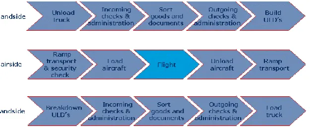
Once the cargo arrives at the designated airport, the ULDs are unloaded and the parts are picked up by Company Z. The parts are then moved to their final destination. The exact handling of airfreight is shown in figure 2-1 below. The three phases describe the handling of cargo in
[image:23.595.140.453.546.675.2]the handlers’ warehouse, on the airport and once the cargo reaches its destination warehouse (Air Cargo - How It Works, 2011).
18
2.2
QUANTIFICATION OF THE CURRENT AIRFREIGHT USE BY COMPANY X
As mentioned in chapter 1, this sub-question is split in the following parts: 2.2.1 HOW EFFICIENT IS THE CURRENT ULD FILLING METHOD?
It is hard to determine how efficient the current ULD filling method is since ULDs are generally filled manually by the designated airport handler. ULDs can also be filled with loose boxes from other companies to utilize more of the ULDs’ space. A ULD can be declared full for two different reasons, namely either dimensional restrictions or weight restrictions. Dimensional restriction mean that the ULD is filled due to the lack of free space. If a ULD is full regarding weight, it means no extra weight can be added to comply with aviation rules. Only a few suppliers have dense cargo that causes the weight limit to be reached first.
In the case of Company X, 95% of ULD’s are declared full due to volumetric reasons.
2.2.2 HOW MUCH DOES AIRFREIGHT COST COMPANY X ANNUALLY?
A report of airfreight booked by Company Z for Company X is used as data to quantify the current airfreight usage. The data in the report starts on 01-01-2017 and ends on 19-12-2017. In total, Company X has issued almost a thousand airfreight orders within this time limit. The total actual revenue is several million euros with an average of several thousands per order. The designed tool creates the efficient cargo layout for a selected IMC and ULD. The amount of IMC units inside the ULD is determined by one of three options; the quantity entered as input, when a ULD is filled regarding dimensions or when the weight limit is reached. The designed cargo layout is compared with the actual used cargo layout.
Taking the abovementioned information into account, this means that the model can be used in 95% of the cases.
2.2.3 HOW MANY BOXES (IMC UNITS) ARE TRANSPORTED VIA AIRFREIGHT ANNUALLY? The report states that thousands of units were transported via airfreight. This results in an average of 4.61 units per order. A unit is either a pallet or a IMC unit and the data is mixed. In section 2.2.5 the data is filtered for comparison. Since several orders can be issued in one day, the assumption is made that, when orders are transported on the same day, they are transported via the same airplane. Based on this assumption the average number of IMC units per flight is 14.66 units per order.
19
2.2.5 ESTIMATED EFFICIENCY OF CURRENT AIRFREIGHT USE
Based on the current shipping data available the exact efficiency of the current airfreight use is not known. The freight handlers are focusing on weight while loading the ULDs and our data show that Company X’s airfreight efficiency is mainly determined by volume. As the loading of the ULDs is mainly done by hand without one single methodology for filling, the filling efficiency is largely individual people dependent. Also the current data mix up loose IMCs with pre-stacked pallets.
In short, the only way to validate the model and to prove that using the model will improve loading efficiency and therefore decrease cost per unit is to set up a trial program, comparing the current method with using the Cargo Layout Model.
Based on a review of the current methods by discussions with Company X- and freight handlers’
employees, it is estimated that using the model could create an increase in loading efficiency of 5%-10%. Whether this efficiency increase will be translated directly into a cost decrease will depend on the appointments with the freight handlers.
A potential saving of 5% on 95% of the IMCs shipped would result in an annual saving of well over a hundred thousand. This potential justifies the initiation of a trial program to verify the effectiveness of the Cargo Layout Model.
2.3
THE PRICING OF AIRFREIGHTED GOODS
There are four aspects that determine the price of airfreight (Pricing - air freight charges, 2017). These are:
1. Gross weight
2. Dimensions and volume 3. Quality of the goods
4. Station of origin and the final destination
Volumetric weight is generally determined using a global rule of thumb for airfreight. First one
finds the item’s volume in cubic meters. This is done by multiplying the length, width and height of the cargo. Next, this number is multiplied by 167 (also known as the 1:6 volume ratio). A
‘weight’ is then determined for the size of the cargo. If the volumetric weight is heavier
compared to the gross weight, this becomes the chargeable weight. If the gross weight exceeds the volumetric weight, this become the chargeable weight. The chargeable weight is generally used by logistical carriers to determine the price of transport.
Combined with the location of origin and the needed destination, and the quality of the goods, a price is determined. The location of origin and the final destination are needed to calculate the total distance the order needs to travel. This logically affects the price.
20 The Federal Aviation Administration forbids the transport of lithium ion and lithium metal batteries via airfreight. This is done due to hazard of abrupt ignition. This rule effects Company X as well, since Company X is not allowed to transport some of their parts via airfreight.
2.4
PALLET USAGE
The build-up of a ULD has several restrictions. In order to use all space, it is needed to know whether it is mandatory to transport goods on a pallet, or if the pallets are broken down and the ULD is build using individual IMC units. The following information was acquired by logistical carrier Company Z.
One can load lose carton on a ULD, but that might create problems for trucking regarding labeling. Each IMC unit on a pallet has a content label on it that can be scanned. This label belongs to a single IMC unit. In addition, each pallet has a total of four receiving labels. These labels are scanned to require the information about the entire pallet. If a pallet is deconstructed, this might create issues for further transport. If it is decided that the IMC units will be transported loose, each IMC unit can get its own receiving label as well. Is thus happens and is possible to load loose IMC units.
When transporting lose IMC units, damage during transport to and from the airport is more likely to occur. The individual boxes are more exposed since an additional action is needed. The contact at logistical carrier Company Z still ensured that the transport individual IMC units is of no problem.
2.5
THE CONDITION OF THE CARGO
Damage to boxes happens, but is rarely caused during air transport. During interviews with team lead airfreight of Company Z, the estimation is made that in maybe 1% of the cases damage occurs. The damage generally is not created during air transportation, but during pick up in the airport warehouses once boxes are removed from the ULD or when during delivery handling.
2.6
IMPROVEMENT OPTIONS
In this section, improvement options regarding the current, manual method of cargo filling are explained. Possible options for improvent are:
• Change in box orientation per layer (Airfreight Handler)
• Quick and easy overview of number of boxes per layer (Airfreight Handler)
• Possibility to prestack pallets according to a specific pallet layout to ensure easy handling and prevent damage (Company X’s Forwarders)
21
3.
THEORETICAL FRAMEWORK
In this chapter, the theoretical framework of this thesis is described. The theoretical framework is needed as a substructure to answer the main research questions and the sub-questions. In order to answer the main research question and the sub-questions, a theoretical framework is used to demarcate the issue and support the solution.
3.1
BIN PACKING
A bin packing problem is a best described as a “finite collection of objects with varying width that is packed into one or more bins or baskets” (Watson, 2007). The goal is to pack all objects such that the least amount of empty space remains. With the increase of the amount of different objects into a bin and the type of dimensions, the difficulty of the problem increases. A bin problem is described as an NP-hard problem. In order to explain what this is, the difference between P and NP problems needs to be explained first.
▪ P is a collection of all decision problems that can be solved in polynomial time. Polynomial time is the time required for a computer to solve a problem, where this time is a simple polynomial function of the size of the input. This thus means that the answer yes or no can be decided in polynomial time.
▪ NP is a complexity of all decision problems for which it is presumed that it is not solvable in polynomial time. An example is the Traveling Salesman Problem (TSP). With a TSP, the shortest route has to be created between cities while returning in the city of origin. It is possible to find an approximate solution but finding the real solution takes significantly longer as the size of the problem increases. Finding an optimal for a NP-problem is therefore not possible.
3.1.1 ONE-DIMENSIONAL, TWO-DIMENSIONAL AND THREE-DIMENSIONAL
As stated above, the difficulty of solving a bin problem increases in the number of dimensions increases as well. The number of options regarding part box placement increases exponentially if dimensions are added (Sweep).
In a one-dimensional bin packing problem, each object has either a fixed height with a variable width or a fixed width with a variable height. As mentioned above, the goal is to pack all object such that the least amount of empty space is left. There are many different packing strategies, these are mentioned in section 3.1.2.
In a two-dimensional bin packing problem, the problem gets more difficult. Both the width and the length vary in the two-dimensional problem as seen in figure 3-1. A restriction that comes with two-dimensional problems is that all objects are orthogonal. This means that an object can be rotated.
22
Figure 3-1: 2-dimensional Bin Packing Figure 3-2: 3- dimensional Bin Packing Step By Step
3.1.2 BIN-PACKING HEURISTICS
As mentioned in the previous section, many different packing strategies exist. Some strategies are shortly explained below (Bin Packing, n.d.).
First fit
The first fit strategy is a very simple strategy that most certainly won’t guarantee optimal layout. The first fit strategy placed the object is the closest point from the starting position that fits. If the object does not fit in the bin, it is put in a new bin or put aside depending on the amount of bins.
First fit decreasing
This strategy is the same as the first fit strategy, except for the fact that the object are first sorted on decreasing size. This means starting with the largest object continuously moving to smaller objects. If an object does not fit, it is also put aside or placed in the next bin.
Best fit
With the best fit strategy, an object is placed in the fullest bin that still has space left for the object. This way, most of the empty spaced is filled.
Worst fit
The worst fit strategy focusses on the opposite bin compared to the best fit, namely the emptiest bin. This is mostly no efficient packing strategy.
Almost worst fit
23 Largest Area Fit First (LAFF) minimizing height
This strategy focusses on the largest area per object and simultaneously minimizes height. This means that objects are placed on the x/y axis, and only if there is no more space the box is placed in the z axis. The different ULDs available all have very strict restrictions, but especially height has an important role. For this reason, the LAFF minimizing height strategy could be used in the thesis.
Knapsack loading
With Knapsack loading, each object has a certain value depending on dimensions, weight, etc. The knapsack has a limited amount of space and thus, a decision needs to be made what object is taken/placed. With knapsack loading, the aim is to minimize leftover space. This is thus an interesting strategy to be used.
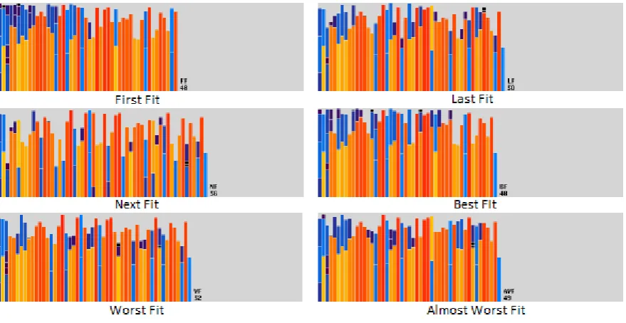
[image:29.595.80.520.419.646.2]Figure 3-3 shows the starting position of a random set. Figure 3-4 shows the results after using certain bin-packing heuristics (Bin Packing, n.d.).
Figure 3-3: Random Set of Objects
24 3.1.3 REAL-WORLD-LIKE PROBLEMS AND RESTRICTIONS
In this section, the connection with real-world-like issues and restrictions are made, since the calculated efficient layout is not always possible due to other restrictions. The major restrictions are mentioned below (Sweep).
Gravity
The restriction gravity is an important factor that needs to be taken into account when designing an efficient cargo layout. If this is not done correctly, there is the risk of a bin falling over or object within a bin getting damaged due to wrong stacking. This is there for an important factor to take into account. Furthermore, in order to withstand gravity, it is important for object and their bins to have a surface to rest on. In Company X’s case this is a pallet.
Weight
The weight of an object is very important to take into account. First of all, each box has a maximum weight. Manhandled boxes have a maximum of 15 KG and in addition, boxes that are picked up via forklift have a unique weight restriction as well. As mentioned in section 1.1.2, container shipments have easier weight restriction compared to airfreight. Since this research thesis focusses on the efficient cargo layout of airfreight, it is important to take the maximum weight restriction per ULD into account. This is something that not all packing strategies implement, but something very important for in this research. In addition, the weight of each bin needs to be taken into account since it is not possible to put a very heavy bin on top of a weaker bin. This will cause an object to get damaged.
Balance
Gravity and weight combined cause for the next concern, namely balance. As mentioned above, gravity needs to be taken into account to decide if an object will fall or not. Besides the correct balance of objects in a bin, the balance of a container or ULD is very important as well. If this is not done correctly, a plane will have a wrong balance point or a cargo ship has the possibility to become unstable.
Priority items
25
4.
METHODOLOGY
In this chapter, the methodology used is described. Section 4.1 describes the research methodology and different methods used. Next, in section 4.2, the applied methodology is described.
4.1
RESEARCH METHODOLOGY
This research thesis uses different data gathering methods needed that verify and validate the current situation and issues, needed for problem solving. Both quantitative research methods as qualitative research methods are used.
Quantitative research methods used in this thesis are historical company data regarding packaging non-compliance. Furthermore, warehouse checks are part of this research method. The carrier warehouse checks are needed to provide Company X with enough information and evidence to penalize suppliers for non-compliance and to start working towards solving the issue.
Qualitative research methods used in the thesis are mostly interviews and attending meetings. Since the logistics team of Company X EMEA is working together with other teams to improve supplier compliance, weekly meetings are held in order to keep track of current situation and any changes.
4.2
APPLIED METHODOLOGY
The applied methodology is described below. In order to answer the main research question, the sub-questions have to be answered first. This section will describe the applied
methodology to answer all sub-questions. The answers to the questions themselves will be given in Chapter 5.
4.2.1 DETERMINING THE CURRENT AIRFREIGHT SITUATION
In this subject, the first sub-question is covered. This subject focusses on finding out how the cargo layout is currently determined by Company X, its carrier or the airport handler. In order to answer this sub-question, qualitative methods are used. This is explained below:
I. Qualitative research: Interviews Logistics Manager Company X & Company Z Team Lead HAL AF ops
❖ Mr. X (Logistics Manager Company X)
26
❖ Mr. Z (Company Z Team Lead HAL AF ops)
Mr. Z handles all of Company X’s airfreight as team lead at logistical carrier Company Z. By interviewing him, details are acquired regarding airfreight with focus on how the airfreight for Company X is handles. Mr. Z furthermore provided percentages needed to check newly designed tool.
4.2.2 THE QUANTIFICATION OF THE CURRENT AIRFREIGHT USE OF COMPANY X
In this section, the applied methodology techniques are described to answer the question regarding the quantification of current airfreight handling. The applied methodology consists of both qualitative as quantitative aspects, which are described below.
I. Qualitative research: Interview with Company Z Team Lead HAL AF ops
In order to quantify the current situation needed to make a comparison between the current situation and the designed tool, additional sub-questions mentioned in chapter 1 are answered by Mr. Z. Most of these answers consist of quantitative numbers, but are accompanied by qualitative explanations.
II. Quantitative research: Annual airfreight cost records
Annual airfreight cost reports are used to quantify the current airfreight usage of Company X. Furthermore, reports acquired via Company Z will be used to design an ‘average’ airfreight
transport which is used to compare the designed tool.
4.2.3 DETERMINING THE PRICING OF AIRFREIGHTED GOODS
This section focusses on methodology of the third sub-question. In order to answer this question, both qualitative as quantitative research is conducted regarding airfreight pricing. The two methods and its findings are described below:
I. Qualitative research: Interviews with Logistics Manager Company X
Meetings with company supervisor Mr. X were held to gain general insight in how airfreight pricing is determined.
II. Quantitative research: Price methods and comparison of logistical carriers
27 4.2.4 THE OBLIGATORY USAGE OF A PALLET
The pallet build-up in a ULD has several restrictions. In order to efficiently use all space, it is needed to know whether it is mandatory to transport goods on a pallet, or if the pallets are broken down and the ULD is build using individual IMC units. This subject is approached using a qualitative method
I. Qualitative Research: Interview with Company Z Team Lead HAL AF ops
Once again, Mr. Z from Company Z described the process and thus the use of a pallet whether after an interview and contact via mail. No quantitative methods are used to answer this sub-question.
4.2.5 THE EFFECTS OF STACKING IMC UNITS
This subject aims at describing possible damage to IMC units when transported via airfreight. To make Company X’s cargo damage more clear, a qualitative research was conducted.
I. Qualitative research: Interview with Company Z Team Lead HAL AF ops
29
5.
EFFICIENT CARGO LAYOUT TOOL
This chapter describes the tool that is designed for the recommendations regarding the efficient cargo layout. This model will be used by Company X’s carriers to design the needed stacking pattern. In section 5.1, the concept of the tool is explained and what information is used. In section 5.2, the simplified problem and phased plan is explained. Next, in section 5.3 the design of the model is described.
5.1
CONCEPT
The concept of this model is explained in this section. The tool will be used by Company X’s
carriers to predetermine the shape of the pallet to make sure the cargo layout is efficiently designed. This will help Company X to transport more boxes via airfreight at a time and thus reduce costs per goods. The tool will allow its user to enter all necessary variables needed to calculate the cargo layout per layer. Restrictions regarding weight, size or quantity will be taken into account as well.
5.2
SIMPLEFIED PROBLEM AND PHASED PLAN
A simplified problem is introduced as a step-by-step visualization of how a ULD is filled with IMC units. In section 5.3.4 a toy problem shows the exact steps with the corresponding calculations per step.
5.2.1 TWO-DIMENSIONAL APPROACH FOR RECTANGULAR CONTAINERS
[image:35.595.77.523.463.507.2]As mentioned above, a toy problem is used to start solving Company X‘s cargo layout problem. The first toy problem only consists in a two-dimensional view for rectangular containers. This way, a basic tool can be designed that can be adapted if other elements are added.
Figure 5-1: Flow Chart 2D Rectangular
30 Below, the step-by-step actions are visualized in figure 5-2.
Figure 5-2: 2D Rectangular Container
5.2.2 THREE-DIMENSIONAL APPROACH FOR RECTANGULAR CONTAINERS
In this section, the toy problem of section 5.2.1 is extended. The height is taken into account as well which means it become a three-dimensional problem. Once again, this is only done for rectangular containers.
Figure 5-3: Flow Chart 3D Rectangular
[image:36.595.78.520.394.493.2]31 The step-by-step visualization is once again shown below in figure 5-4, 5-5 and 5-6.
[image:37.595.177.418.255.395.2]Figure 5-4: Step 1 3D Rectangular Container
[image:37.595.179.418.425.561.2]Figure 5-5: Step 2 3D Rectangular Container
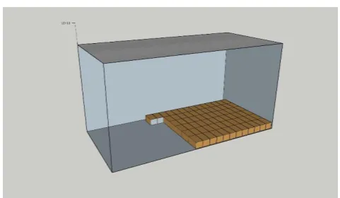
32 5.2.3 THREE-DIMENSIONAL APPROACH FOR CONTAINERS WITH A SLOPED SIDE
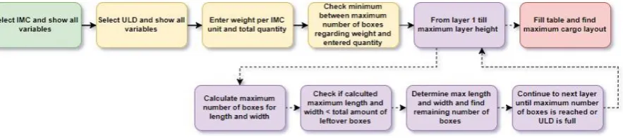
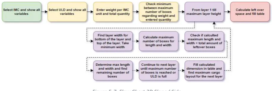
[image:38.595.68.525.142.295.2]In this section, the toy problem is adjusted to be similar to the actual problem for Company X. Containers are added with sloped sides. This means that for each layer, the width has to be calculated for the top and bottom of the IMC unit. The path is shown below in figure 5-7
Figure 5-7: Flow Chart 3D Sloped Side
Once again, the first steps are similar to the flowcharts shown in the previous two sections. By adding ULDs with a sloped side, the toy problem becomes increasingly difficult. The amount of IMC units that fit in the length stay the same, whereas the amount of boxes that fit in the width can differ per layer. For that reason, the width of the layer is checked for both the top as the bottom of the layer current layer. The minimum width is taken and used to calculate the amount of boxes that fit in the width. The next steps are the same as mentioned in section 5.2.2 except in the end, the total left space in the length and width per layer is calculated.
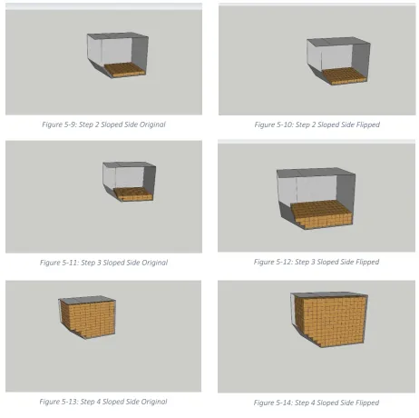
The figures 5-8 till figure 5-14 show the step by step filling of a ULD for both orientations.
33
Figure 5-9: Step 2 Sloped Side Original Figure 5-10: Step 2 Sloped Side Flipped
Figure 5-11: Step 3 Sloped Side Original Figure 5-12: Step 3 Sloped Side Flipped
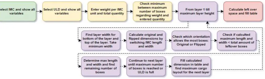
[image:39.595.65.528.68.528.2]34 5.2.4 ADDING A SECOND ORIENTATION
The fourth and final step is to adjust the toy problem to look at check both orientations. This means the ULD length and width always stay the same, but the IMC unit can be changed over the x-axis. This means the length and width of the IMC unit are swapped to calculate if more
[image:40.595.76.521.190.323.2]boxes fit in the ‘Original’ orientation or in the ‘Flipped’ orientation. This is explained in section 5.3.4. The orientation is checked per layer and the orientation that allows the most IMC units is chosen as seen in figure 5-15.
Figure 5-15: Flow Chart 3D Second Orientation
The step-by-step visualization is shown in the figure in section 5.2.3. Two orientations mean the box is flipped 90 degrees along the z-axis. This is shown in figure 5-16 below.
[image:40.595.125.473.440.597.2]35
5.3
DESIGN
In this section, the tool design is explained. This consists of several parts. These parts discuss the features of the tool and the data they show. Next, the assumptions made in order to for the model to work will be described. Finally, the VBA code and tool design will be explained. In this part, the usage of the model will be explained as well.
5.3.1 INPUT
The designed tool allows its user to enter five different input variables. These variables are: • IMC option (type of box)
• Quantity
• Weight per IMC • ULD option • Pallet (Y/N)
The IMC option cell gives its user the ability to pick one of the 43 IMC options Company X has for the European & Asia pacific. Each IMC option has its own restriction as shown in appendix 2 When the IMC option is selected, the used has to manually enter the total quantity of IMC options needed to be transported via airfreight. Furthermore, the weight per IMC has to be entered since this is important to make sure the weight restriction of an ULD is not exceeded. The ULD option is a dropdown list of the ULD options used by Company X that fit in a wide-body aircraft. There are two types of ULD. The first type are rectangular ULDs. These are easier to fill since the space per layer always stays the same. The second ULD type are ULDs with a sloped side. This sloped side makes efficient cargo layout more difficult since rectangular IMC options will not fit without leaving a blank space. The tool needs to check the width of the container after each layer to see if an extra box can be added, a box has to be removed or the next layer has the same restrictions.
36 5.3.2 ASSUMPTIONS
The tool is designed in such a way that certain assumptions are made that in a real-life situation would not always be valid. The assumptions made are stated below and explained why the assumption is made.
• The angle of sloped ULDs is always the same.
The main focus of this research is on wide-body aircrafts. The height restriction is always 162.6 cm for the ULDs. ULDs with a sloped side have a varying width and thus the number of boxes that fit differ per layer level. In order to calculate the width difference per height difference, an angle of 48.65 ° is taken. This angle is calculated from known ULD dimensions. Since the lower hold of a wide-body aircraft is similar, the rounding of the planes are similar as well. Since not all ULD dimensions are known, the assumption is made that all angles of the sloped sides of ULDs are 48.65 °
• The thickness of ULDs
ULDs are made from aluminum in order to be as light as possible since weight is a major restriction for airplanes. This means that the aluminum is as thin as possible. Since the thickness of the aluminum is rarely given on carrier website, the assumption is made that the outer layer dimensions are the same as the inner dimensions. These dimensions are taken from a carrier’s
website and validated by comparing them to several sources. • Homogenuous ULDs
As explained above, a ULD is filled with IMCs. In a real-life situation, a supplier can choose to have a mixed pallet load. This means that the supplier has at least two sorts of IMCs on a pallet. During the demarcation of this research thesis, the conclusion was drawn that the amount of products transported result in several pallets at a time. For this reason, it is chosen to see all ULDs homogeneous ULDs, which means that the ULD is filled with only one sort of IMC.
• Stackability of an IMC option
It is taken into account that all similar IMC options are stackable. This means that is it expected that this is possible considering weight restrictions. As stated in the abovementioned assumption, only one sort of IMC is used per ULD. This means that the assumption is made that, if the size restrictions allow it, all IMCs inside the ULD are stackable.
• Leftover space per ULD
37 • Pallet dimensions only effect height.
As mentioned above, the checkbox function ‘Pallet’ is an input function of the tool. The height of the standardized pallets that Company X lets its suppliers use is 12.3 cm. The assumption is
made that, when the ‘Pallet’ checkbox is checked, only the height of the pallet is taken into account as an extra height restriction. The length and the width of the pallet is not take into account. This is done since most ULDs are not able to fit two pallets side by side. Furthermore, the price of airfreight is determined by volume and weight, and thus only the height of the pallet will affect the amount of boxes that fit.
• Orientation per layer
Due to the scope of this thesis and for simplicity, the assumption is made that only one
orientation is used per layer. Each layer thus either has an ‘Original’ or ‘Flipped’ orientation.
There is no difference in orientation within a certain layer. 5.3.3 OUTPUT
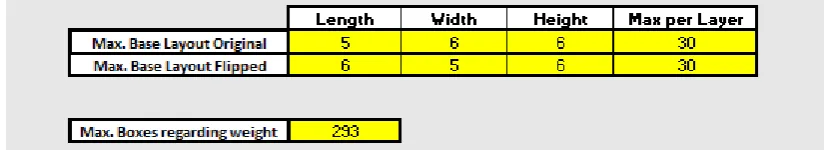
The Excel/VBA tool has several different output variables in a total of seven different parts. The output of the tool is used as an instruction on how to efficiently pack the ULD, and show all restrictions. In order to fully explain what output variables the tool displays, the seven parts will be described one by one. These are explained below:
• IMC dimensions and restrictions
After selecting an IMC option as an input variable, the tool shows the dimensions of the IMC in the cells next to the IMC option. Furthermore, the max. weight restriction is shown. If the weight of the IMC entered as an input variable is larger than the max. IMC weight, a message box tells its user that the IMC option is too heavy.
• ULD dimensions and restrictions
The dimensions and restrictions of a ULD option are more extended compared to the IMC output. The ULD output variables have the length, height and max weight similar to the IMC part, but extra output variables are shown as well. Since not all ULDs are rectangular, there can be a difference regarding the base width and the top width. This means that more/less boxes fit in the base of the ULD compared to the top and thus the efficient cargo layout can change per layer. In order to calculate the cargo layout for ULDs with a sloped side, the ‘height of the slope’ and the ‘Rate of change of width’ is needed. The height of the slope tells the tool at what
height the sloped side of the ULD starts.
The ‘rate of change of width’ is best described as the change in width per height change. For
instance, the LD-29 has a ‘Rate of change of width’ of 1.76. This means that for each cm that