E-mail: [email protected] Engineers. 关DOI: 10.1117/1.2844700兴
Subject terms: mode-referencing; external cavity diode laser; frequency stabilization.
Paper 070021R received Jan. 9, 2007; revised manuscript received Oct. 1, 2007; accepted for publication Oct. 17, 2007; published online Mar. 3, 2008.
1 Introduction
The ability to stabilize the emission from a diode laser to a reference frequency is of great importance for many appli-cations including optical telecommuniappli-cations, injection locking of high-power lasers, and spectroscopic based studies.1–4 However, depending on the type of device in-volved, control of the frequency-stabilizing mechanism may vary in complexity. For example, some widely tune-able sources with multisection architectures, such as the sampled-grating distributed Bragg reflector 共SG-DBR兲 la-ser, require several current sources to drive the device, and very precise manipulation of these is required to control and stabilize the output emission wavelength.5 This situa-tion is similar to that pertaining to the external cavity diode laser共ECDL兲, where the emission wavelength is controlled by both injection current to the laser and a voltage to a piezoelectric transducer共PZT兲, which controls the position of the external grating.6ECDLs have long been a source of great interest due to their wide wavelength tuning capabil-ity, high output power, and, of course, the narrow linewidth available with an external cavity.7,8
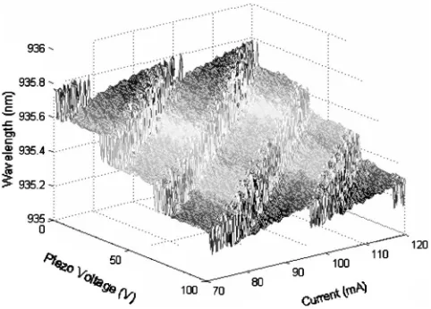
To operate the ECDL such that the wavelength is tuned in a continuous, mode-hop-free manner, which is essential for successful frequency stabilization, a tuning contour plane was first recorded and is shown in Fig. 1. This is achieved by changing both current and PZT voltage simul-taneously over a certain range and measuring the output power from the laser. Once a picture of the ECDL emission mode profile is obtained in this manner, a series of points are chosen along a region of the contour map, and these points are fitted with a polynomial. By simultaneously tun-ing the injection current and PZT voltage values, deter-mined by the polynomial fit, the desired wavelength region can be scanned in a continuous linear fashion, as indicated by the dashed arrow in Fig. 1. In general, for most widely tuneable laser diodes, a similar situation pertains in that a
mode profile of the output emission is first obtained so that correct operating currents can be chosen for continuous wavelength tuning of the device.9Of course, it is assumed that the mode profile initially recorded remains constant with time so that the device can operate in a continuous wavelength tuning mode without fail using the determined control parameters. Unfortunately, this is not the case for some widely tuneable laser diodes10,11 and for the ECDL used in this work.
A shift in the tuning contour plane was observed over time caused by thermal or mechanical instabilities in the complex design of the laser.12Obviously, this has a delete-rious knock-on effect if the device is used in a frequency stabilization scheme, where a loss in continuous wave-length tuning ultimately leads to a complete failure in the frequency stabilization of the laser output. To counteract
0091-3286/2008/$25.00 © 2008 SPIE
[image:1.612.318.559.521.694.2]this problem, a mode-referencing technique was imple-mented into the frequency stabilization scheme similar in concept to a form of mode stabilization for a superstructure grating DBR共SSG-DBR兲laser.13 Referencing 共adjustment of operation parameters兲of the ECDL 共while maintaining frequency lock兲ensures that the constant frequency emis-sion remains on a characteristic line in the power plane equidistant from adjacent mode boundaries, which corre-sponds to the optimum operating point. With the mode-referencing step, it was possible to achievein situ monitor-ing of the position of the current/PZT voltage combination tuning path and compensate for any drift in the mode pro-file by locking the wavelength-tuning path to the center of the desired lasing mode. We demonstrate experimentally that it is possible to maintain frequency stabilization of an ECDL output to a H2O absorption line with the inclusion of the mode-referencing technique in the frequency-locking system, while applying a series of induced temperature steps, simulating thermal instability, to the device heat sink.
2 Experimental Details
An ECDL operating in the Littrow architecture was fre-quency stabilized to a H2O absorption line at 935.684 nm using wavelength modulation spectroscopy.14,15 共WMS兲. The spectral characteristics of the ECDL were initially measured and the device showed good single-mode emis-sion at room temperature with a side-mode suppresemis-sion ra-tio 共SMSR兲⬎40 dB and the spectral linewidth of the
de-vice was ⬍300 kHz, measured using a short-arm
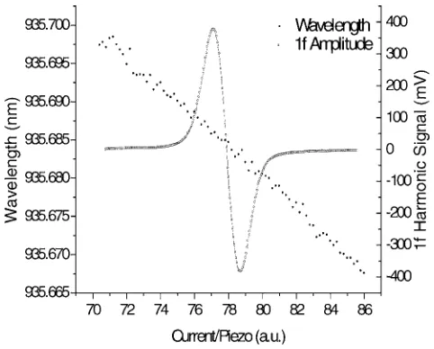
homodyne technique. The maximum continuous mode-hop-free wavelength tuning of the laser, over the full range of the injection current and the PZT voltage, was measured to be approximately 0.45 nm and the maximum output power was ⬎60 mW. Figure 2 shows the 1f demodulated signal of the H2O absorption line with the zero-crossing point at the line center used to frequency lock the ECDL along with the continuous wavelength tuning of the laser output. In any frequency stabilization system, it is necessary to
gen-erate an error signal between a reference frequency to which the laser output locks and the actual emission fre-quency of the device. In our case, the output of the ECDL was passed through a 1-m-long cell containing water vapor at a constant pressure of 25 mbar, and the resulting absorp-tion signal was detected with a photodetector. A WMS scheme was implemented with the PZT being modulated at approximately 14 kHz and a lock-in amplifier was used to process the detected signals. The modulation depth was set so that a maximum peak to peak amplitude on the 1f de-modulated signal was achieved. Modulating the external grating is preferred, as it helps reduce any amplitude-modulated component that is normally present with injec-tion current modulainjec-tion.
The frequency stabilization of the ECDL was controlled with a dual-feedback locking loop, which helped improve the overall performance and accuracy of the device. The feedback loop for the control of the ECDL is composed of two parts, a slow loop that tunes along the wavelength tun-ing contour with a combination of injection current and grating adjustment, and a second faster loop that controls the grating only. Since the fast loop drives only the grating piezoactuator, and not the laser current, there is no thermal interaction present so that the fast loop can operate at shorter timescales共milliseconds兲in comparison to the slow loop. To demonstrate this scheme both parts of the feed-back system were implemented as simple filtered propor-tional controllers, low pass for the slow branch and band-pass for the fast branch. For the slow branch, the low-band-pass filter cutoff and the proportional gain term are chosen to avoid any oscillatory behavior in the laser output frequency and to obtain critically damped behavior in the response to a step in laser current.16 The high-frequency side of the bandpass response of the fast branch was similarly deter-mined, while the low-frequency side 共within the slow loop response兲 ensures that the low-frequency components are handled by the slow loop along the tuning contour. Figure 3 shows the experimental setup for the frequency stabiliza-tion of an ECDL using a reference gas cell. A schematic description of the dual-feedback loop and the mode-Fig. 2 Measurement of the 1fharmonic signal of a detected water
vapor absorption line at 935.684 nm used to lock the frequency of the device and the continuous wavelength tuning operation of the ECDL.
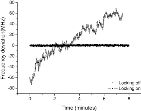
[image:2.612.54.295.59.253.2] [image:2.612.319.556.59.224.2]referencing step are also included in the figure. The result of the frequency stabilization of the ECDL output using the dual-feedback loop approach, by locking to the zero cross-ing of the 1f harmonic of the H2O absorption line at 935.684 nm, is presented in Fig. 4. The graph shows a comparison for the two cases where the locking is switched on and switched off for a period of 8 min. The drift in frequency of the ECDL output when the locking is turned off is due to temperature effects and the free-running insta-bility of the device. The overall accuracy of the frequency stabilized ECDL output to the absorption line center was measured to be less than ⫾1.5 MHz.
3 Mode Referencing
As previously discussed, the necessity for a mode-referencing step to control the emission frequency of the stabilized ECDL source emerged as a direct result of prob-lems faced due to thermal and mechanical instability of the device and a consequential change in the contour mode plane. The contour mode plane determines the values of the injection current/PZT voltage combination, which provide the tuning path for continuous mode-hop-free wavelength tuning. One method that was initially considered for the mode-referencing step involved turning off the frequency-locking procedure, fixing the PZT voltage, and then tuning the laser output with injection current only, across the las-ing mode. The range of the current tunlas-ing was set large enough so that the mode boundaries on either side of the lasing mode were crossed. Then by differentiating the re-sulting power change across the mode boundaries, recorded with the internal monitor photodiode of the device, the cen-ter of the lasing mode was acquired, the tuning path of the current/PZT voltage was realigned to the center of the las-ing mode, and the frequency locklas-ing was subsequently switched back on. Obviously this worked well to reference the position of the lasing mode, but the major disadvantage of this method is a loss in frequency stabilization of the ECDL output with the locking switched off between scans, which ultimately would lead to a total failure of the
stabilization is in operation, a modulation is applied to the current of the wavelength-tuning path. The tuning contour path is determined by a second-order polynomial fit, which selects the best fit of values of injection current/PZT volt-age combination so that a well-defined wavelength-tuning contour path is achieved. The mode-referencing procedure enables the laser wavelength to remain constant because the a0 term is in a perpendicular direction to the wavelength-tuning path. This step is indicated in Fig. 5, where the dashed line indicates the injection current/PZT voltage combination, which determines the wavelength-tuning path, and the arrow, which describes the modulation in the perpendicular direction to the wavelength-tuning path. A more detailed scan of the variation in output power of the ECDL, measured with the internal monitor photodiode across the mode, is shown in Fig. 6.
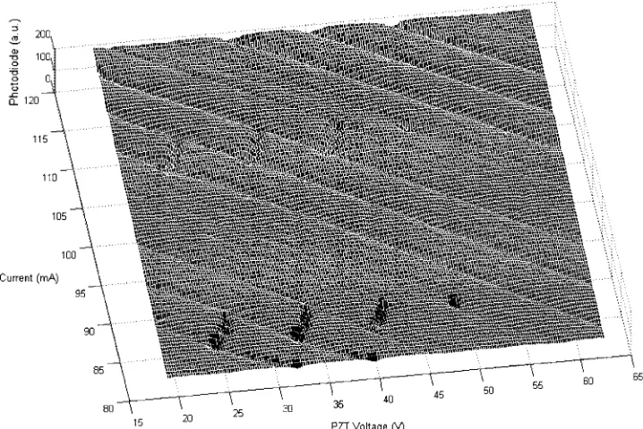
With this change in power, it was possible to set the amplitude of the modulation on thea0term large enough so that a value for peak power, corresponding to the center of the lasing mode, was measurable. Then it was simply a matter of setting up another feedback loop so that the wavelength-tuning path could be locked to the peak power of the lasing mode and, hence, locked to the center of the lasing mode. As the modulation on thea0term of the poly-nomial is in the direction perpendicular to the direction of continuous wavelength tuning, the locking frequency is maintained at the desired wavelength. The basis on which the emission wavelength of the ECDL can be maintained at the same value throughout the mode-referencing operation is explained clearly with reference to Fig. 5. The graph shows the recorded photodiode power of the detected laser radiation as a function of injection current and PZT voltage over a certain range, after passing through the 1-m gas cell containing water vapor at 25 mbar. From the trace, the po-sitions of the various water absorption lines are identified by the points of reduced photodiode signal on the contour mode map. Note that the level of absorption is constant across the different modes. This confirms that the wave-length, in the direction perpendicular to the direction of the wavelength-tuning path, is constant so that the ECDL out-put can remain frequency stabilized to the desired wave-length 共H2O line at 935.684 nm兲throughout the mode ref-erencing operation.
4 Results
To demonstrate the performance of the mode-referencing step a series of deliberate temperature changes to the ECDL Fig. 4 Frequency stabilization performance of the ECDL with the
[image:3.612.54.293.61.249.2]heat sink were executed while the laser output was fre-quency stabilized. Figure 7 shows the output frefre-quency of the ECDL while the device is frequency stabilized using the dual-feedback loop with the mode referencing switched on, as the heat sink temperature is varied from 23 to 24° C in 0.10° C steps by simply adjusting the temperature control-ler. It is clear that the output frequency of the stabilized ECDL does not vary by more that 5 MHz for the duration
共30 min兲of the test. The change in temperature to the heat sink of the device essentially causes the contour mode pro-file to change, and this requires a change in the operating points of the current and PZT voltage if frequency locking
to the desired frequency is to be maintained. The mode-referencing tracks the change in the mode profile position with temperature, and then with the dual-feedback locking loop, the necessary changes to the injection current and PZT voltage are made. Figure 8 shows the variation in the current and PZT voltage for the duration of the test as the temperature is changed in 0.1° C increments for a total of 1 ° C. With the increase in temperature from 23 to 24° C it is clear that this results in an increase in PZT voltage from 28.4 to 35.0 V and a decrease in injection current from 110.5 to 107.3 mA. It is also possible to see in the figure Fig. 5 Mode profile of ECDL emission measured with the detection through a water vapor cell at 24° C
from 80 to 120 mA and 18 to 62 V as the current and PZT voltage are scanned. The points on the mode plane where water absorption lines are located are also clearly visible from the dips in the mode map, which correspond to a reduction in transmitted signal onto the photodiode.
Fig. 6 Recorded MP showing the variation of the output power across a particular lasing mode. The current is kept constant and the PZT voltage is varied at constant temperature of 24° C.
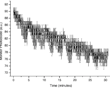
[image:4.612.127.486.61.301.2] [image:4.612.317.556.518.707.2] [image:4.612.54.298.528.708.2]the effect of the modulation on the a0 term of the wave-length tuning path, clearly visible in the constant variation of the injection current. Finally, the trace in Fig. 9 shows the output power of the ECDL, recorded with the internal MP, as the temperature changes are made. An overall re-duction in output power occurs as the mode referencing causes a change to both the current and PZT voltage while constantly maintaining frequency stabilization to the de-sired wavelength of 935.684 nm.
5 Conclusions
The use of a novel mode-referencing technique was intro-duced, and was clearly shown to aid in the frequency sta-bilization of the output of an ECDL in conjunction with a dual-feedback locking loop. The addition of the mode-referencing step greatly improved the operation and reli-ability of the frequency stabilization system that controls the frequency output of the laser. Its performance was
frequency locking.
References
1. Y. Sakai, I. Yokohama, T. Kominato, and S. Sudo, “Frequency stabi-lization of laser diode using a frequency-locked ring resonator to acetylene gas absorption lines,”IEEE Photonics Technol. Lett.3共10兲, 868–870共1991兲.
2. T. Sato, M. Niikuni, S. Sato, and M. Shimba, “Frequency stabilisation of a semiconductor laser using Rb-D1and D2absorption lines,” Elec-tron. Lett.24共7兲, 429–431共1988兲.
3. A. Sollberger, A. Heinamaki, and H. Melchior, “Frequency stabiliza-tion of semiconductor lasers for applicastabiliza-tions in coherent communica-tion systems,”J. Lightwave Technol.5共4兲, 485–491共1987兲. 4. C. R. Prasad, V. A. Fromzel, J. S. Smucz, I. H. Hwang, and W. E.
Hasselbrack, “A diode-pumped Cr:LiSAF laser for UAV-based water vapor differential absorption lidar共DIAL兲,” inProc. Geoscience and
Remote Sensing Symp., IGARSS 2000, Vol.4, pp. 1465–1467, IEEE
共2000兲.
5. V. Jayaraman, Z. M. Chuang, and L. A. Coldren, “Theory, design, and performance of extended tuning range semiconductor lasers with sampled gratings,” IEEE J. Quantum Electron. 29共6兲, 1824–1834 共1993兲.
6. M. W. Fleming and A. Mooradian, “Spectral characteristics of external-cavity controlled semiconductor lasers,” IEEE J. Quantum Electron.QE-17, 44–59共1981兲.
7. R. Wyatt and W. J. Delvin, “10 kHz linewidth 1.5m InGaAsP ex-ternal cavity laser with 55 nm tuning range,”Electron. Lett.19, 110– 112共1983兲.
8. B. Boggs, C. Greiner, T. Wang, H. Lin, and T. W. Mossberg, “Simple high-coherence rapidly tunable external-cavity diode laser,” Opt. Lett.23, 1906共1998兲.
9. G. Sarlet, G. Morthier, and R. Baets, “Control of widely tunable SSG-DBR lasers for dense wavelength division multiplexing,” J. Lightwave Technol.18共8兲, 1128–1138共2000兲.
10. F. Delorme, G. Terol, H. de Bailliencourt, S. Grosmaire, and P. Devoldere, “Long-term wavelength stability of 1.55-m tunable dis-tributed Bragg reflector lasers,”IEEE J. Sel. Top. Quantum Electron. 5共3兲, 480–486共1999兲.
11. S. L. Woodward, P. Parayanthal, and U. Koren, “The effects of aging on the Bragg section of a DBR laser,”IEEE Photonics Technol. Lett. 5共7兲, 750–752共1993兲.
12. S. A. Al-Chalabi, J. Mellis, M. Hollier, K. H. Cameron, R. Wyatt, J. E. Regnault, W. J. Devlin, and M. C. Brain, “Temperature and me-chanical vibration characteristics of a miniature long external cavity semiconductor laser,”Electron. Lett.26, 1159–1160共1990兲. 13. H. Ishii, F. Kano, Y. Yoshikuni, and H. Yasaka, “Mode stabilization
method for superstructure-grating DBR lasers,”J. Lightwave Tech-nol.16, 433–442共1998兲.
14. D. S. Bomse, A. C. Stanton, and J. A. Silver, “Frequency-modulation and wavelength modulation spectroscopies—comparison of experi-mental methods using a lead-salt diode-laser,”Appl. Opt.31, 718– 731共1992兲.
15. M. W. Fleming and A. Mooradian, “Spectral characteristics of external-cavity controlled semiconductor lasers,” IEEE J. Quantum Electron.17, 44–59共1981兲.
16. J. R. Leigh,Control Theory, 2nd ed., Chap. 3, Institution of Electrical Engineers共2004兲.
Biographies and photographs of authors not available. Fig. 8 Injection current and PZT voltage variation as the mode
ref-erencing step is in operation for the induced changes in the heat sink temperature of the ECDL.
[image:5.612.55.295.57.230.2] [image:5.612.56.290.507.693.2]