warwick.ac.uk/lib-publications
Original citation:Antonio, B., Randall, J., Hensinger, W. K. , Morley, Gavin and Bose, S. (2015) Classical computation by quantum bits. arXiv (1509.03420). (Unpublished)
Permanent WRAP URL:
http://wrap.warwick.ac.uk/100518
Copyright and reuse:
The Warwick Research Archive Portal (WRAP) makes this work by researchers of the University of Warwick available open access under the following conditions. Copyright © and all moral rights to the version of the paper presented here belong to the individual author(s) and/or other copyright owners. To the extent reasonable and practicable the material made available in WRAP has been checked for eligibility before being made available.
Copies of full items can be used for personal research or study, educational, or not-for-profit purposes without prior permission or charge. Provided that the authors, title and full bibliographic details are credited, a hyperlink and/or URL is given for the original metadata page and the content is not changed in any way.
A note on versions:
The version presented here is a working paper or pre-print that may be later published elsewhere. If a published version is known of, the above WRAP URL will contain details on finding it.
arXiv:1509.03420v1 [quant-ph] 11 Sep 2015
B. Antonio1, J. Randall2,3, W. K. Hensinger2, G. W. Morley4, S. Bose1
1Department of Physics and Astronomy, University College London,
Gower Street, WC1E 6BT London, United Kingdom
2Department of Physics and Astronomy, University of Sussex, Brighton, BN1 9QH, UK 3 QOLS, Blackett Laboratory, Imperial College London, London, SW7 2BW, UK and
4Department of Physics, University of Warwick, Gibbet Hill Road, Coventry CV4 7AL, United Kingdom
Atomic-scale logic and the minimization of heating (dissipation) are both very high on the agenda for future computation hardware. An approach to achieve these would be to replace networks of transistors directly by classical reversible logic gates built from the coherent dynamics of a few interacting atoms. As superpositions are unnecessary before and after each such gate (inputs and outputs are bits), the de-phasing time only needs to exceed a single gate operation time, while fault tolerance should be achieved with low overhead, by classical coding. Such gates could thus be a spin-off of quantum technology much before full-scale quantum computation. Thus motivated, we propose methods to realize the 3-bit Toffoli and Fredkin gates universal for classical reversible logic using a single time-independent 3-qubit Hamil-tonian with realistic nearest neighbour two-body interactions. We also exemplify how these gates can be composed to make a larger circuit. We show that trapped ions may soon be scalable simulators for such architectures, and investigate the prospects with dopants in silicon.
Introduction:– Power dissipation has become a
seri-ous obstacle to packing more transistors per unit area so that the exponential rise of computational power with time (Moore’s law) may be continued. Heating in a chip is pro-jected to reach200Wcm−2by 2020 [1] by the International Technology Roadmap for Semiconductors (ITRS). The search for less dissipative alternatives is on with sugges-tions such as molecular electronics [2], spin-wave compu-tation [3], magnetic and quantum dot cellular automata [4], DNA logic [5] and superconducting logic in cryogenic tem-peratures [6], which are by no means exhaustive.
Aside from minimizing dissipation, another driving fac-tor for contemporary computer technology is the atomic scale storage of information [2, 7, 8] and atomic scale logic [9]. However, to our understanding, they do not yet aim to exploit the dynamics of highly isolated systems for computation in the same sense as the “friction free” bil-liard ball computer of Fredkin and Toffoli [10]. Such dy-namics is well approximated in the systems being devel-oped for quantum technologies where quantum coherence is preserved by a high isolation. In fact, the energy dissi-pation time-scaleT1 can be exceptionally high, and even the dephasing time T2 is fairly high. It is thereby worth studying whether the huge development towards quantum computation can, on the way to that grand goal, also pro-vide a minimally dissipative, as well as miniaturized, hard-ware for classical logic. Any reliability sacrificed by going to atomic bits is not particularly new at this scale, and, is present even at the nano-scale, and ingenious ways of using low-reliability devices is topical [11–13].
Motivated by the above, here we investigate whether an unmodulated minimal widget of 3 permanently interacting qubits, with each qubit encoding a microscopic bit, can act as a logic gate for classical computation. The aim is to (a) use coherent dynamics (to avoid dissipation and heating), (b) use permanent nearest neighbour two-body couplings
of similar strength (to keep things realistic for a structure of proximal spin qubits, for example), (c) use a single “time-independent” Hamiltonian to accomplish the entire gate and finally, (d) avoid any auxillary systems, hybrid systems or additional levels aside those of the relevant qubits. In practical implementations, additional regular pulsings may however be required for reducing decoherence through dy-namical decoupling. We suggest placing these gates next to each other spatially to compose a classical circuit (we also exemplify this composability). The whole classical circuit will then simply be a 2D pattern of the widgets im-plementing the fundamental gates, where each such gate is implemented by a quantum evolution. However, the quan-tum state is allowed to decohere “before” and “after” each gate. This is acceptable for a classical circuit as the inputs and outputs of each gate are classical bits, and no superpo-sition has to be maintained between the end of one basic gate and the start of another. Unlike the case for quantum computation, in the space of time between the gates, the correction of dephasing errors are not necessry. The use of classical codes therefore suffices to keep track of the errors within the computation.
2
[18, 21–25] or the motional modes in ion traps [17, 26], or auxillary levels outside the space of qubits [25, 27, 28]. Where solely qubits have been used, either multiple pulses [29] or non-uniform and long-range couplings (departing from aim (b)) are generically present as in the NMR and other literature [30, 31]. Crucially, the key question of the “possibility” and an analytic expression of the “accuracy” of gates in the simplest setting: 3 qubits and a time inde-pendent realistic nearest neighbour Hamiltonian, remains open. In fact, the conjuction (a)-(d) should be impossible as the generation of the unitary operations corresponding to the ideal Fredkin and Toffoli gates with a single (time-constant) 3 qubit Hamiltonian seems to necessitate unreal-istic 3-body interactions [32, 33] σz
iσj ·σk andσizσjzσkx
respectively. However, it has gone unnoticed that when we lower our aim from quantum to classical computation, i.e., when the relative phases between the computational basis states are irrelevant, and when approximate gates with low errors could be useful, then classical Fredkin and Toffoli gates of useful accuracy become feasible with 3 qubit real-istic nearest neighbour time-independent Hamiltonians.
Toffoli gate:- A classical Toffoli gate flips the target bit
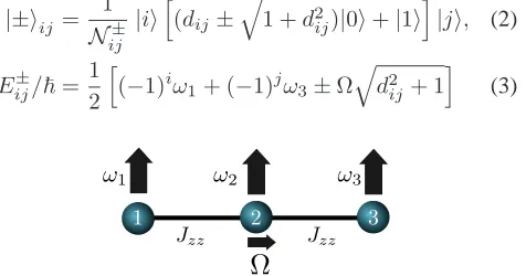
when both the control bits are in the logical state 1 (a quantum Toffoli is a unitary operator that additionally en-codes a specific phase relationship between distinct quan-tum states). We start by describing how a structure of 3 permanently Ising coupled spins can be used to implement an approximate classical Toffoli gate and investigate how good the approximation can be. The gate is switched on by applying a transverse field to the target qubit (qubit 2 in this case, see fig. 1). With this field switched on, the gate is performed through the time-independent Hamiltonian
HTOF=
Jzz
2 (σ
z
1σ2z+σ2zσ3z) + X
j
ωjσzj
2 +
Ωσx
2
2 , (1)
where Jzz, ωj andΩ are in frequency units (unless
oth-erwise specified we will use these units). For the Toffoli gate we require √1
2|1i(|0i ±e
iφ|1i)|1ito be eigenstates of
HTOF. By applyingHTOF on states of this form, it can be confirmed thatω2 = 2Jzz achieves the desired eigenstate
withφ = 0, whileω1 andω3 can remain arbitrary. The eigenstates and energies are then
|±iij=
1
N±
ij
|iih(dij±
q
1 +d2
ij)|0i+|1i
i
|ji, (2)
Eij±/~= 1
2
h
(−1)iω1+ (−1)jω3±Ω q
d2
ij+ 1
i (3)
FIG. 1. Setup for creating a 3-qubit Toffoli gate.
wherei, j ∈ {0,1},d11 = 0,d01 = d10 = ω2/Ω,d00 =
2ω2/Ω, and Nij± are normalising factors. The |101i ↔ |111i swapping will occur when exp [−iHTOFt]|101i =
eiθ|111i, which occurs at a time t = τ
n = (2n +
1)π~/|E+
11−E11−| = (2n+ 1)π/Ω (wherenis an inte-ger, and assuming without loss of generality thatΩis pos-itive). In general, the evolution of the arbitrary computa-tional basis states in this timeτnis captured by the
fideli-tiesflmn→xyz :=hxyz|e−iHTOFτn|lmni. As[H
TOF, σ1z] =
[HTOF, σ3z] = 0only the following fidelities are relevant
fabc→a¯bc =
−ie−iφac(2n+ 1)π
2 sinc
(2n+ 1)π 2
p
d2
ac+ 1
fabc→abc =−ie−iφac
cos
(2n+ 1)π 2
p
d2
ac+ 1
−(2n+ 1)iπ
2 dacsinc
(2n+ 1)π 2
p
d2
ac+ 1
(4)
where a, b, c ∈ {0,1}, ¯b := b ⊕ 1, and φac =
(2n+1)π((−1)aω
1+(−1)cω3)
2Ω . Note that |f101↔111| = 1by our choice ofτn. To realise a Toffoli gate we further require
that|fi0j →fi1j|= 0for|iji 6= |11iso that for these
fi-delities, the phase inside the sinc function in (4) must be an integer multiple ofπ. This leads us to
1 2
r
ω2 2
Ω2 + 1 =
m1
(2n+ 1), 1 2
r
4ω2 2
Ω2 + 1 =
m2
(2n+ 1),
(5)
wherem1, m2are non-zero integers, which in turn implies
16m2
1−4m22 = 3(2n+ 1), where the left hand side is even, and the right side is odd. Thus no choice ofω2,Ωgives a perfect Toffoli (a price to pay for the simplicity ofHTOF).
However, we can find parameters which achieve an ap-proximate gate. Assuming n = 0 for the shortest pos-sible gate time and further assuming that the first sube-quation of Eq.(5) is exact with largem1 one findsm2 ≈
2m1 from the second subequation of Eq.(5). With this choice of parameters, the phases inside the sinc func-tions in (4) are all either multiples ofπor approximately so up to order 1/m1. To evaluate how close this ap-proximate Toffoli is to the exact Toffoli, we use the pro-cess trace distance, which for a 3-qubit system is defined as [34]Dpro = tr|χ(U)−χ(T)|/16whereχ(M)mn =
tr(A†
mM)(tr(A†nM))∗, and {An}64n=1 is a complete or-thogonal basis which satisfiestr(A†
nAm) = δnm,T is an
ideal Toffoli gate,U is the gate we can achieve with the above setup, and |X| indicates the matrix norm. As we are interested in creating a “classical” gate, we ignore any phases and defineU|f| such thathy|U|f||xi = |fx→y|so
this will only measure how close we are to a Toffoli gate apart from local operations.Dprogives an upper bound on
the average probabilityp¯ethat the gate fails [34], so
¯
pe.Dpro= 3π
16m2 1 +O 1 m4 1 ≈ 3π
4 (Ω/ω2)
In summary, we can achieve an approximate classical Tof-foli gate with average failure error of Eq.(6), ifJzz=ω2/2 andω2/Ω =
p
4m2
1−1, withm1large.
Fredkin Gate:- We now consider creating a classical
Fredkin gate (controlled-SWAP), using quantum Ising and Heisenberg interactions. We consider the Hamiltonian
HFRED=
J
2σ2·σ3+ Jzz
2 σ
z
1σ2z+ X
j
ωjσzj
2 , (7)
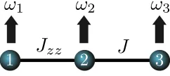
where qubit 1 is the control qubit, and qubits 2 and 3 are to be swapped (see fig. 2). The intuition is that the swap-ping induced by the Heisenberg interaction between qubits 2 and 3 will only occur when qubit 1 is in a state that makes the energy splitting of qubits 2 and 3 match. For swap be-tween qubits2and3, we need to choose parameters such that states of the form √1
2(|110i ± |101i)are eigenstates of
HFRED, which requiresJzz =ω2−ω3. With these parame-ters,{|100i,|111i,|011i,|000i}are all eigenstates, and the only eigenstates of the Hamiltonian which are not compu-tational basis states are
|ψi±110 = (|110i ± |101i)/
√
2, |ψi±010={J|010i+ (ω2
−ω3± p
(ω2−ω3)2+J2)|001i}/N010± (8)
where N010± is a normalising factor. The eigenener-gies of these states are E110± /~ = −(ω1+J∓2J)/2
andE010± /~ = ω1−J±2pJ2
zz+J2
/2respectively. The swap |110i ↔ |101i is complete at a time τn =
(2n+ 1)π~/|E+
110 −E110− | = (2n+ 1)π/2J (with n ∈
{0,1,2, ...}, and assumingJ >0, without loss of general-ity). The fidelity for swapping|010i ↔ |001iat timeτn
is ∝ sinc h
(2n+ 1)πpJ2
zz+J2/J
i
. For this fidelity to be zero, we needJ2 m2/(2n+ 1)2−1
= (ω2−ω3)2, wheremis an integer greater than 1, and (2nm+1) >1.
Possible realizations:- In implementations, the gate
op-eration times, ∼ 1/Ω for the Toffoli, and∼ 1/J for the Fredkin, have to be smaller than the dephasing times. We discuss two possible realizations.
Trapped Ions:- To engineer the HamiltonianHTOFwe ex-ploit the fact that an axial magnetic field gradient realises Ising couplings [35]. Consider three171Yb+ions in a lin-ear Paul trap with secular frequencyν= 2π×100kHz. The qubits are encoded in the 2S1/2 |↓i = |F = 0, mF = 0i
and|↑i=|F = 1, mF = 1istates which are separated by
[image:4.612.116.237.635.689.2]approximately12.6GHz. For∂zBj = 250Tm−1, one has
FIG. 2. Setup for creating a 3-qubit Fredkin gate, using Ising and Heisenberg coupling.
J12=J23=Jzz = 2π×9.98kHz,J13= 2π×7.07kHz. The extraJ13coupling introduces extra phases to the gate but this has no effect if the gate is used for classical compu-tation. Theσx
2 field is achieved by applying a near-resonant microwave pulse leading to the trapped ion Hamiltonian
H(i) =
3 X j=1 ω0 j 2 σ z j + Jzz 2 2 X j=1
σzjσjz+1+ Ω cos(ωxt)σ2x,
(9)
where ω0
j is the qubit energy splitting of ion j. We
can transformH(i) to a frame rotating with the operator 1
2( P
jωj0σjz −δσz2), where δ is the detuning of the mi-crowave field from the resonant frequency of ion 2. States in this rotating frame evolve according to
HI(i)= δ 2σ z 2 + Jzz 2 2 X j=1
σzjσjz+1+ Ωei(δ−ω
0 2)σ
z
2tcos(ω
xt)σx2
Choosingδ = 2Jzz andωx = ω20−δ, and applying iden-tity 13 of the supplementary material, we have
HI(i)=HTOF(ω2 = 2Jzz, ω1 =ω3 = 0) +O
Ω 2ω0
2−4Jzz
.
Thus with Ω = 2π × 1.8kHz and ω0
2 ∼ 12.6GHz,
HI(i) ≈HTOF, while the systematic gate error from Eq.(6) is∼ 0.02. The gate time is∼ 0.3ms, giving an error due to decoherence of around (1− e−tgate/T2)
∼ 0.03with
T2 ≈ 10ms [36] using dynamical decoupling). In addi-tion there may be addiaddi-tional heating due to proximity of the ions to the electrode surface, which we estimate from the results in [37]. For a cryogenically cooled surface trap with an ion-electrode distance of 160µm we estimate an additional decoherence rate of 50 Hz, which results in an error of around 0.01. Overall we therefore expect an aver-age gate with error∼ 0.04, which should be good enough for error-free classical circuitry [38–41].
Bismuth Donors in Silicon:- We propose placing the
donor atoms [42–48] close to each other so that their elec-tronic spins are permanently coupled by isotropic Heisen-berg interactions. To engineerHTOF, the nuclear spins are prepared in different states [42, 49]{Iz
1, I2z, I3z}, resulting in different hyperfine couplings (with the very high cou-pling strengthA= 1.475GHz of Bi) at each site. Starting from a nuclear spin polarised sample [50] we can flip the nuclear spin from92 to−9
2 in 9 steps of∼10µseach. The nuclear spins are stable for hours [51, 52], so this process could be done once before many operations of the gate. We use a magnetic fieldωL >> Ato ensure the nuclear spin
does not evolve. The Hamiltonian of the donors is then [53]
H0(d) =ωL
3 X
n=1
Snz+
3 X
n=1
AInzSnz+
2 X
n=1
Jn,n+1Sn·Sn+1,
(10) whereSnα = 12σαn withα = x, y, zare the Pauli matrices
4
on qubit 2 in thex-direction (which could be applied glob-ally since the hyperfine splittings are different) so that the Hamiltonian H(d) = H0(d) + Ω cos(ωxt)S2x acts on the donors. Setting J12 = J23 = J, ωx = ωL+AI2z −J and transformingH(d)to a frame rotating with the opera-torωLP3n=1Snz −JS2z+
P3
n=1AInzSnz results in (using
identities 13-14 of the supplementary material)
HI(d)= HTOF(Jzz=J, ω2= 2J, ω1=ω3= 0) 2
+O
3 X
n=2
J
|AIz
n−AInz−1|
+ Ω
2(ωL−2J+AI2z) !
.
Setting Iz
1 = 92, I2z = −92, and I3z = 92, and with
Ω = 1MHz,J= 30MHz, both the error term inHI(d)and the systematic gate error term in Eq.(6) are∼ 10−3. The gate time is2µs(thereby allowing the bandwidth of the AC pulse to significantly exceed the∼2kHz linewidths seen in experiments [54]) so that the errors due to decoherence are roughly1−e−tgate/T2
∼10−6(asT
2∼700ms in isotopi-cally pure silicon [55]).
The Fredkin gate can be implemented solely withH0(d). TransformingH0(d) to a rotating frame with the operator
ωLP3n=1Snz+AI1zS1z+AI2z(S2z+S3z)and using the iden-tity 14 of the supplementary material gives
H0(d,I)= 1
2HFRED(Jzz=J12, J=J23, ω2
− ω3 = 2A(I2z−I3z)) +O(J12/|AI1z−AI2z|). (11)
SettingIz
1 =−92, I2 = 9 2, I3 =
7
2, Fredkin gate conditions
J12 = 2(AI3z − AI2z) = J23 q
m2
(2n+1)2 −1 can be met
byJ23 = J12(1 + 10−6)(n = 675, m = 2340) with a resulting gate time∼0.5µs= 10−3T
2so that decoherence is negligible. The error term in Eq.(11) is∼0.22, but could be minimized further to∼ 0.07by techniques mentioned in the supplementary material.
Composability:- To exemplify circuit building, we show
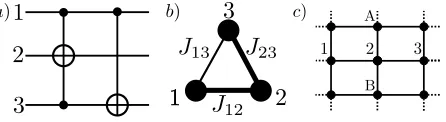
how a half-adder (fig. 3 a)) [56] can be implemented with the arrangement of Ising coupled spins shown in fig. 3 b). The Toffoli gate with qubit 2 as target is implemented using
HTOF. Then we want to apply the controlled-NOT irrespec-tive of the state of qubit 2. Two successive pulses on qubit 3 of frequenciesω+andω−, whereω±=ω3−J13±J23 im-plement two successive conditional flips of qubit 3 accord-ing to when qubits 1 and 2 are in a|10i12 and|11i12 re-spectively. Each of these pulses implement different time-independent Hamiltonians in appropriate rotating frames. Thus, 3 successive time independent Hamiltonians imple-ment a half adder. In general, a Toffoli gate can be applied on a set of qubits (say, 1, 2 and 3 with 2 as target) of the Ising coupled array depicted in fig. 3 c), by pulses of 4 fre-quencies to flip qubit 2 irrespective of the state of those neighbours (say, A and B) that do not take part in the gate. While our pulsing is similar to tools in liquid state NMR
[30, 56], it was not apparent to date that the gates possible in the simplest of settings are approximate, inequivalent to the unitary operations corresponding to Fredkin and Toffoli gates (to achieve those further “non-local” gates are neces-sary), and do not require long-range couplings.
FIG. 3. a) A half-adder circuit. b) Setup for creating a half adder,
using two pulses and withJ12 = J23 6= J13. c) Using
selec-tive addressing on arrays of qubits, general computations can be achieved.
Reliability:- Our physical realizations have errors (as in
any nano-scale logic, including scaled CMOS). However, reliable classical computation with faulty components is possible with a constant overhead [38, 40] as our error rates are below the1/6required threshold [57]. One can use measurements between gates and a classical resetting of bits (e.g., parity protected gates [58]). Besides, applica-tions such as image processing tolerate more noise [13]. If we automate error correction with faulty gates such as in “quantum” error correction, thresholds∼10−2−10−3are however obtained (see Supplementary Material ), which are still met by the donor based implementation ofHTOF.
Conclusions:- We have demonstrated how the
classi-cal Toffoli and Fredkin gates can be achieved by realis-tic 3 qubit time-independent Hamiltonians. This focus on simplicity (e.g., time-independence, no auxillary sys-tems/levels) as opposed to fidelity [28], stems from aim-ing to build low dissipation atomic-scale classical logic. Targeting classical gates helps us circumvent the apparent impossibility of the ideal Toffoli and Fredkin unitaries un-der our desiun-derata (a)-(d). Although AC pulses were used in the proposed implementations with trapped ions and Bi donors, and for building circuits, these were merely a means to implement the time-independentHFREDandHTOF in appropriate rotating frames. This only results in extra relative phases between the computational basis states that do not matter for classical computing. While our gates minimize the dissipation in computation, the study of dis-sipation while pulsing and measuring and the possibility of room temperature realizations [59] is kept for the future.
[image:5.612.331.554.126.187.2]Commissions Seventh Framework Programme (FP7/2007-2013) under Grant Agreement No. 270843 (iQIT), the Army Research Laboratory under Cooperative Agreement No. W911NF-12-2-0072, the US Army Research Office Contract No. W911NF-14-2-0106 and the University of Sussex. The views and conclusions contained in this docu-ment are those of the authors and should not be interpreted as representing the official policies, either expressed or im-plied, of the Army Research Laboratory or the U.S. Gov-ernment. The U.S. Government is authorized to reproduce and distribute reprints for Government purposes notwith-standing any copyright notation herein.
[1] S.-C. Lin and K. Banerjee, IEEE Transactions on Electron Devices 55, 245 (2008).
[2] N. Lorente and C. Joachim, Architecture and Design of
Molecule Logic Gates and Atom Circuits, Advances in
Atom and Single Molecule Machines (Springer, 2013). [3] M. Kostylev, A. Serga, T. Schneider, B. Leven, and B.
Hille-brands, Applied Physics Letters 87, 153501 (2005).
[4] A. Imre, G. Csaba, L. Ji, A. Orlov, G. Bernstein, and
W. Porod, Science 311, 205 (2006).
[5] S. Khullar, V. Chopra, and M. S. Kahlon, in National
Con-ference on Challenges & Opportunities in Information Tech-nology, RIMT-IET, Mandi Gobindgarh (2007).
[6] D. Holmes, A. Ripple, and M. Manheimer, Applied Super-conductivity, IEEE Transactions 23 (2013).
[7] F. Delgado and J. Fern´andez-Rossier, Phys. Rev. Lett. 108, 196602 (2012).
[8] S. Loth, S. Baumann, C. P. Lutz, D. Eigler, and A. J. Hein-rich, Science 335, 196 (2012).
[9] M. Fuechsle, J. A. Miwa, S. Mahapatra, H. Ryu, S. Lee, O. Warschkow, L. C. Hollenberg, G. Klimeck, and M. Y. Simmons, Nature Nanotechnology 7, 242 (2012).
[10] E. Fredkin and T. Toffoli, International Journal of Theoreti-cal Physics 21, 219 (1982).
[11] L. Anghel and M. Nicolaidis, in Computational and
Ambi-ent Intelligence (Springer, 2007) pp. 422–429.
[12] K. Palem and A. Lingamneni, ACM Transactions on Em-bedded Computing Systems (TECS) 12, 87 (2013). [13] J. Han and M. Orshansky, in Test Symposium (ETS), 2013
18th IEEE European (IEEE, 2013) pp. 1–6.
[14] C. Bennett, IBM Journal of Research Development 17, 525. [15] R. Landauer, IBM Journal of Research Development 5, 183
(1961).
[16] D. G. Cory, M. D. Price, W. Maas, E. Knill, R. Laflamme, W. H. Zurek, T. F. Havel, and S. S. Somaroo, Phys. Rev. Lett. 81, 2152 (1998).
[17] T. Monz, K. Kim, W. H¨ansel, M. Riebe, A. S. Villar, P. Schindler, M. Chwalla, M. Hennrich, and R. Blatt, Phys. Rev. Lett. 102, 040501 (2009).
[18] A. Fedorov, L. Steffen, M. Baur, M. P. da Silva, and
A. Wallraff, Nature 481, 170 (2012).
[19] M. A. Nielsen and I. L. Chuang, Quantum Computation and
Quantum Information (Cambridge University Press, 2004).
[20] N. Yu, R. Duan, and M. Ying, Phys. Rev. A 88, 010304 (2013).
[21] A. M. Chen, S. Y. Cho, and M. D. Kim, Phys. Rev. A 85, 032326 (2012).
[22] C.-Y. Chen, M. Feng, and K.-L. Gao, Phys. Rev. A 73, 064304 (2006).
[23] Y.-F. Xiao, X.-B. Zou, and G.-C. Guo, Phys. Rev. A 75, 054303 (2007).
[24] X.-Q. Shao, T.-Y. Zheng, X.-L. Feng, C. Oh, and S. Zhang, J Opt. Soc. Am. B 31, 697 (2014).
[25] S.-B. Zheng, Phys. Rev. A 87, 042318 (2013).
[26] S. S. Ivanov and N. V. Vitanov, Phys. Rev. A 84, 022319 (2011).
[27] T. Ralph, K. Resch, and A. Gilchrist, Phys. Rev. A 75, 022313 (2007).
[28] E. Zahedinejad, J. Ghosh, and B. C. Sanders, Phys. Rev. Lett. 114, 200502 (2015).
[29] S. S. Ivanov, P. A. Ivanov, and N. V. Vitanov, Phys. Rev. A
91, 032311 (2015).
[30] J. Du, M. Shi, J. Wu, X. Zhou, and R. Han, Phys. Rev. A
63, 042302 (2001).
[31] P. Kumar, Quantum Information Processing 12, 1201 (2013).
[32] H. Chau and F. Wilczek, Phys. Rev. Lett. 75, 748 (1995). [33] R. Ionicioiu, T. P. Spiller, and W. J. Munro, Phys. Rev. A
80, 012312 (2009).
[34] A. Gilchrist, N. K. Langford, and M. A. Nielsen, Phys. Rev. A 71, 062310 (2005).
[35] C. Wunderlich, Laser Physics at the Limits (Springer, Hei-delberg, 2001).
[36] C. Piltz, B. Scharfenberger, A. Khromova, A. F. Var´on, and C. Wunderlich, Phys. Rev. Lett. 110, 200501 (2013). [37] M. D. Hughes, B. Lekitsch, J. A. Broersma, and W. K.
Hensinger, Contemporary Physics 52, 505 (2011). [38] J. Von Neumann, Automata Studies 34, 43 (1956).
[39] R. L. Dobrushin and S. Ortyukov, Problemy Peredachi In-formatsii 13, 56 (1977).
[40] N. Pippenger, G. D. Stamoulis, and J. N. Tsitsiklis, Infor-mation Theory, IEEE Transactions on 37, 639 (1991). [41] U. Feige, P. Raghavan, D. Peleg, and E. Upfal, SIAM
Jour-nal on Computing 23, 1001 (1994).
[42] G. W. Morley, M. Warner, A. M. Stoneham, P. T. Greenland, J. van Tol, C. W. Kay, and G. Aeppli, Nature Materials 9, 725 (2010).
[43] M. H. Mohammady, G. W. Morley, and T. S. Monteiro, Phys. Rev. Lett. 105, 067602 (2010).
[44] M. H. Mohammady, G. W. Morley, A. Nazir, and T. S. Mon-teiro, Phys. Rev. B 85, 094404 (2012).
[45] S. J. Balian, M. B. A. Kunze, M. H. Mohammady, G. W. Morley, W. M. Witzel, C. W. M. Kay, and T. S. Monteiro, Phys. Rev. B 86, 104428 (2012).
[46] G. W. Morley, P. Lueders, M. Hamed Mohammady, S. J. Balian, G. Aeppli, C. W. M. Kay, W. M. Witzel, G. Jeschke, and T. S. Monteiro, Nature Materials 12, 103 (2013). [47] G. Wolfowicz, A. M. Tyryshkin, R. E. George, H. Riemann,
N. V. Abrosimov, P. Becker, H.-J. Pohl, M. L. W. Thewalt, S. A. Lyon, and J. J. L. Morton, Nat. Nano. 8, 561 (2013). [48] G. Morley, Review: Towards Spintronic Quantum
Technolo-gies with Dopants in Silicon, Chapter 3, Electron
Param-agnetic Resonance 24 (The Royal Society of Chemistry, 2015).
[49] R. Kalra, A. Laucht, C. D. Hill, and A. Morello,
6
[50] T. Sekiguchi, M. Steger, K. Saeedi, M. L. W. Thewalt, H. Riemann, N. V. Abrosimov, and N. N¨otzel, Phys. Rev. Lett. 104, 137402 (2010).
[51] G. Feher and E. A. Gere, Phys. Rev. 114, 1245 (1959). [52] T. G. Castner, Phys. Rev. Lett. 8, 13 (1962).
[53] B. Kane, Nature 393, 133 (1998).
[54] A. Laucht, J. T. Muhonen, F. A. Mohiyaddin, R. Kalra, J. P. Dehollain, S. Freer, F. E. Hudson, M. Veldhorst, R. Rahman, G. Klimeck, K. M. Itoh, D. N. Jamieson, J. C. McCallum, A. S. Dzurak, and A. Morello, Science Advances 1 (2015). [55] G. Wolfowicz, S. Simmons, A. M. Tyryshkin, R. E. George, H. Riemann, N. V. Abrosimov, P. Becker, H.-J. Pohl,
S. A. Lyon, M. L. W. Thewalt, and J. J. L. Morton,
Phys. Rev. B 86, 245301 (2012).
[56] A. Roy and D. Chatterjee, American Journal of Com-puter Science and Information Technology (AJCSIT) 3, 139 (2015).
[57] B. Hajek and T. Weller, IEEE Transactions on Information theory 37, 388 (1991).
[58] B. Parhami, in Signals, Systems and Computers, 2006.
AC-SSC’06. Fortieth Asilomar Conference on (IEEE, 2006) pp.
1726–1729.
[59] N. Y. Yao, L. Jiang, A. V. Gorshkov, P. C. Maurer, G. Giedke, J. I. Cirac, and M. D. Lukin, Nature Communi-cations 3, 800 (2012).
[60] D. D’Alessandro, Introduction to Quantum Control and
Dy-namics (Chapman and Hall/CRC, 2008).
[61] E. Knill, R. Laflamme, and W. H. Zurek, Science 279, 342 (1998).
[62] B. Koiller, X. Hu, and S. Das Sarma, Phys. Rev. Lett. 88, 027903 (2001).
[63] B. Koiller, X. Hu, and S. Das Sarma,
Phys. Rev. B 66, 115201 (2002).
[64] J. L. O’Brien, S. R. Schofield, M. Y. Simmons, R. G. Clark, A. S. Dzurak, N. J. Curson, B. E. Kane, N. S. McAlpine, M. E. Hawley, and G. W. Brown, Phys. Rev. B 64, 161401 (2001).
[65] S. R. Schofield, N. J. Curson, M. Y. Simmons, F. J. Rueß, T. Hallam, L. Oberbeck, and R. G. Clark, Phys. Rev. Lett.
91, 136104 (2003).
[66] H. J. Mamin, M. Poggio, C. L. Degen, and D. Rugar, Nat. Nano. 2, 301 (2007).
Interaction picture and the rotating wave approximation
Consider a Hamiltonian that contains some fast oscillat-ing terms of the formV cosωt, whereV is time indepen-dent and Hermitian. Ifω >kVk, then the evolution opera-tor can be approximated by (see e.g. [60])
U(t,0) =1+O
kVk
ω
(12)
To represent this, we will use the notationH(t) =H0(t) +
OkVωk. We now derive two identities that are useful in the main text. For this first identity, consider a Hamiltonian term of the formCe−iωσzt/2cos(ωxt)σxeiωσ
zt/2
. Setting
ωx =ωgives
Ce−iωσzt/2cos(ωt)σxeiωσzt/2
=Ce−iωσztcos(ωt)σx= C 2e
−iωσzt
σx(eiωt+e−iωt)
= C
2(e
−iωtσ++eiωtσ−)(eiωt+e−iωt)
= C
2 σ
++e2iωtσ−+e−2iωtσ++σ−
= C
2σ
x+O
C 2ω
(13)
provided thatC < 2ω. For the second identity, consider a Hamiltonian of the form e−it[ω1σz1+ω2σz2]/2J(σx
1σ2x +
σy1σy2+σ1zσz2)eit[ω1σ z
1+ω2σ
z
2]/2
Je−it[ω1σ1z+ω2σz2]/2(σx
1σx2 +σ1yσ
y
2 +σz1σz2)eit[ω1σ z
1+ω2σz2]/2
= 2Je−it[ω1σz1+ω2σz2](σ+
1σ2−+σ1−σ+2) +Jσ1zσ2z
= 2Jσ1+σ−2eit[ω1−ω2]
+ 2Jσ1−σ+2e−it[ω1−ω2]
+Jσz1σz2
=Jσz1σ2z+O
4J ω1−ω2
(14)
provided4J <(ω1−ω2).
Thresholds for fault-tolerant classical computation
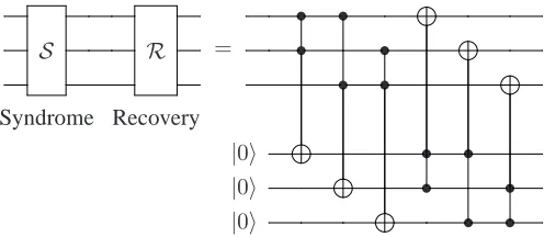
We will estimate the error threshold required to imple-ment a fault-tolerant classical Toffoli gate, using the sim-plest classical code, the 3-bit repetition code. We will use a similar analysis as in [19, 61], which is not a very rigourous analysis but will give a rough idea of the kind of classical threshold we will need to achieve with the Toffoli gate. A simple classically fault-tolerant Toffoli circuit can be con-structed as follows:
•
S R
C1 •
•
Syndrome Recovery
•
S R
C2 •
•
Syndrome Recovery
S R
T
Syndrome Recovery
S R
• •
= • •
• •
Syndrome Recovery
|0i • •
|0i • •
|0i • •
Since the code is robust against single classical (bit-flip) er-rors, a rough expression for the fault tolerant gate threshold can be found by considering the ways in which 2 or more errors can occur. Two errors can be output by a single fault-tolerant Toffoli gate in the following ways:
1 There are incoming errors in two or more of the in-puts, which can propagate through the gate to create two errors on one encoded qubit. Incoming errors would be from a single error exiting from a previ-ous syndrome / recovery step, which could happen at any of six points in the syndrome / recovery process. There are3C2= 3ways that two errors could be in-coming, so if the error of a bit flip in the gate ispthe total probability is3×(6p)2 = 108p2.
2 There is an incoming error in one of the inputs, and an error in the first round of Toffoli gates. Incoming errors have probability6p, and the probability of one error in any of the three gates is3p. There are 3 ways this can happen so the overall probability is3×3p×
6p= 56p2.
3 Two errors occur during the Toffoli gates. There are 3C
2= 3ways this can happen, so the total probabil-ity is3p2.
4 One failure occurs during the Toffoli gates (three ways this can happen), and one during one of the syn-drome gates (3 ways this can happen). Total proba-bility for all three encoded qubits is3×3p×3p= 27p2.
5 Two failures occur during one of the syndrome gates (3C2ways this can happen per encoded qubit). Total probability is3×3p2 = 9p2.
6 One failure occurs during the syndrome gate and one during the recovery. Total probability3×3p×3p= 27p2.
7 Two or more failures during recovery; total probabil-ity9p2.
In total, this gives a rough probability of(108+56+3+27+ 9 + 27 + 9)p2 = 239p2of two errors occurring undetected
in the fault-tolerant Toffoli gate. Thus following concate-nation of this encoding (see e.g. [19]) we would expect er-rors in the gate below the thresholdp. 2391 ≃ 5×10⁻³ to give a fault tolerant Toffoli gate.
Parameter set for Fredkin Gate with Bismuth donors
To satisfy the conditions of the Fredkin gate, J12 =
2(AIz
3 −AI2z)andJ232 ( m
2
(2n+1)2 −1) = 4(AI3z −AI2z)2.
For the minimal gate time (n = 1), this would give
J23 = √13J12, or alternativelyJ23could be tuned to dif-ferent fractions ofJ12 by altering m and n. For exam-ple, we can achieve J23 = J12(1 + 10−6) by setting
n = 675andm = 2340. The resulting gate time would be675×0.5ns∼0.5µs= 10−3T
[image:8.612.52.300.72.180.2]2, so such tuning would still not lead to large decoherence errors.
FIG. 4. Adding a fourth qubit to the original setup, in order to
relax the constraints onJzzand provide a control to turn the gate
on and off.
WithJ12 = 2(AI3z −AI2z), the error term in H (d) 0,I is
O(2(Iz
2 −I3z)/(I1z −I2z)), which is minimal whenI1z =
−9 2, I2 =
9 2, I3 =
7
2. To decrease this error, a fourth qubit could be included, as shown in Fig. 4. Adding this qubit
Ewith Ising coupling JE2 effectively adds another local magnetic field to qubit 2 and so changes the resonance con-dition toJ12+JE2 = ω3 −ω2 (assuming that this qubit is set in the|0istate). Note however that this coupling also has an error associated to it, and so the optimal situation is withJE2 = J12 = (AI3z −AI2z) = 1.475GHz. This results in an error of around 11%. Adding yet another con-trol qubitE′ with coupling JE′2 and choosing couplings such thatJ12= JE2 =JE′2 = 23(AI3z −AI2z)results in
errors of around 7% (adding any more becomes unrealistic as the control qubits may begin to interact significantly). The gate time in this situation would be∼ 1.5ns which is still significantly smaller thanT2.
8
toJ12(this magnetic field would also decrease the error in
H0(d,I)). Since it would be possible to bring a magnetic tip close to the sample, large magnetic field gradients of up to
107Tm−1would be possible [66] so thatω2−ω3could be tuned by up to ±0.5GHz. Alternatively, we could adopt the method in [53], and use electric gates to tune the inter-donor couplings and increase hyperfine interactions, how-ever this might introduce extra noise due to charge fluctua-tions.
We could go further and use an extra qubit as an on/off switch for the gate, which could be useful if we wish to concatenate several of these gates together. Consider the setup in Fig. 4 that has one additional external qubit,
la-belled qubit E. For qubit E to act as a control, we just need to make sure that the resonances of qubits 2 and 3 only match when qubits 1 and E are in the |1i state, and are very different otherwise so that the Heisenberg coupling becomes effectively an Ising coupling. By finding the res-onance energy of qubit 2 under different settings of qubits 1 and E, and choosingJ12=J2E, we find that the following
conditions must be satisfied
A+ 2J12≫J23, A≫J23, A−2J12≃0 (15)