warwick.ac.uk/lib-publications
Original citation:Yang, Zhen, Tian, Yanling, Yang, C.J., Wang, Fujun and Liu, Xianping. (2017) Modification of wetting property of Inconel 718 surface by nanosecond laser texturing. Applied Surface Science, 414 . pp. 313-324.
Permanent WRAP URL:
http://wrap.warwick.ac.uk/88746
Copyright and reuse:
The Warwick Research Archive Portal (WRAP) makes this work by researchers of the University of Warwick available open access under the following conditions. Copyright © and all moral rights to the version of the paper presented here belong to the individual author(s) and/or other copyright owners. To the extent reasonable and practicable the material made available in WRAP has been checked for eligibility before being made available.
Copies of full items can be used for personal research or study, educational, or not-for-profit purposes without prior permission or charge. Provided that the authors, title and full bibliographic details are credited, a hyperlink and/or URL is given for the original metadata page and the content is not changed in any way.
Publisher’s statement:
© 2017, Elsevier. Licensed under the Creative Commons Attribution-NonCommercial-NoDerivatives 4.0 International http://creativecommons.org/licenses/by-nc-nd/4.0/
A note on versions:
The version presented here may differ from the published version or, version of record, if you wish to cite this item you are advised to consult the publisher’s version. Please see the ‘permanent WRAP url’ above for details on accessing the published version and note that access may require a subscription.
Modification of wetting property of Inconel 718 surface by
nanosecond laser texturing
Z. Yang a,b,c, Y.L. Tian a,b,c, C.J. Yang a,b,*, F.J. Wang a,b, X.P. Liu c
aSchool of Mechanical Engineering, Tianjin University, Tianjin 300350, China
bKey Laboratory of Mechanism Theory and Equipment Design of Ministry of Education, Tianjin
University, Tianjin 300350, China
cSchool of Engineering, University of Warwick, Coventry CV4 7AL, UK
Corresponding author e-mail address: [email protected] (C.J. Yang)
Abstract
Topographic and wetting properties of Inconel 718 (IN718) surfaces were modified via
nanosecond laser treatment. In order to investigate surface wetting behavior without
additional post treatment, three kinds of microstructures were created on IN718
surfaces, including line pattern, grid pattern and spot pattern. From the viewpoint of
surface morphology, the results show that laser ablated grooves and debris significantly
altered the surface topography as well as surface roughness compared with the
non-treated surfaces. The effect of laser parameters (such as laser scanning speed and laser
average power) on surface features was also discussed. We have observed the treated
surface of IN718 showed very high hydrophilicity just after laser treatment under
ambient air condistion.And this hydrophicility property has changed rapidly to the other
extreme; very high hydrophobicity over just about 20 days. Further experiments and
analyses have been carried out in order to investigate this phenomena. Based on the
XPS analysis, the results indicate that the change of wetting property from hydrophilic
to hydrophobic over time is due to the surface chemistry modifications, especially
carbon content. After the contact angles reached steady state, the maximum water
contact angle (WCA) for line-patterned and grid-patterned surfaces increased to 152.3
1.2° and 156.81.1° with the corresponding rolling angle (RA) of 8.81.1° and 6.5 0.8°, respectively. These treated IN718 surfaces exhibited superhydrophobic
property. However, the maximum WCA for the spot-patterned surfaces just increased
modification of surface wettability has high sensitivity to surface morphology and
surface chemical compositions. This work can be utilized to optimize the laser
processing parameters so as to fabricate desired IN718 surfaces with hydrophobic or
even superhydrophobic property and thus extend the applications of IN718 material in
various fields.
Keywords: Inconel 718, Nanosecond laser, Surface morphology, Surface wettability,
Surface chemical compositions
1. Introduction
As a precipitation-hardenable superalloy, IN718 has been widely used to make
critical components of gas turbines, power plants, spacecraft and rocket motors due to
its excellent corrosion resistance, thermal resistance, wear resistance and high strengths
at elevated temperature [1-3]. However, IN718 is commonly classified as the difficult
machining material because of high shear strength, low material removal rate and
excessive tool wear by conventional machining methods [4]. Although it is reported
that current hybrid manufacturing methods can pave a way to solve the aforementioned
problems, there are many shortcomings such as high cost, long lead-time and
environmental impacts that cannot meet the requirement for wide applications of IN718
material [5-6]. Thus it is urgent to seek alternative technique expanding the value of
such material in potential applications.
Currently, extensive attention has focused on superhydrophobic surfaces that play
a significant role in various applications related to energy, resources and environment,
including self-cleaning, anti-fogging, anti-corrosion, anti-icing, anti- bacteria and drag
reduction [7-17]. Superhydrophobic surface is generally defined as a solid surface with
water contact angle (WCA) exceeding 150° and rolling angle (RA) below 10° [18, 35].
It is well-known that both surface topology and surface chemistry determine the wetting
property of a particular solid surface. Therefore, surface wettability can be changed by
surface roughness modification and by changing surface chemical component.
According to Wenzel model [19] and Cassie-Baxter model [20], surface roughness
manipulation can contribute to improving hydrophobicity of the solid surfaces. In
of rough surface. The contact angle θW can be modified by the following equation:
cos𝜃𝑊= 𝑟 cos𝜃 (1)
Where r >1 is surface roughness parameter, θ represents contact angle for flat
surface and is determined by the chemical compositions of surface layer. It can be
deduced from the Eq. (1) that contact angle will decrease with increased roughness of
a hydrophilic surface, whereas contact angle will increase when the roughness of a
hydrophobic surface increases. Nevertheless, in most cases found in reality, the contact
between a droplet and a rough surface is never complete. Indeed, air pockets are trapped
in the grooves, which leads to Cassie-Baxter model with a composite interface. The
contact angle θCB on such surfaces is given as follow:
cos𝜃𝐶𝐵 = 𝑟𝑓𝑓 cos𝜃 + 𝑓 − 1 (2)
For Cassie-Baxter model, the key factors affecting contact angle value are the
roughness parameter of wetted area rf, the portion of surface wetted by testing liquid f
and the chemical compositions of surface layer, associated with θ [21]. Therefore,
according to Eq. (2), one can modify θCB on the rough surface by simply varying surface
morphology and, as a result, the portion of wetted solid area f. Theoretically, a
superhydrophobic surface can be achieved on any intrinsically hydrophilic materials
[22-24].
Inspired by wetting model and the famous “lotus effect” with self-cleaning
property, researchers have fabricated artificial superhydrophobic surfaces by the
combination of two important factors: micro/nanoscale hierarchical structures and low
surface energy substances. Based on the basis of such principle, a variety of methods
have been employed to obtain thermodynamically stable hydrophobic or even
superhydrophobic surfaces through controlling both of the surface chemical
components and surface morphological structures, such as sol-gel coating [25-26],
electrochemical deposition [27], chemical etching [28], laser surface texturing [29-31]
and spray-coating [32]. Among these options, laser treatment is a promising technique
to create superhydrophobic surfaces [33].
According to previous literatures, surface wettability can be modified to exhibit
chemical modification. Boinovich [34] reported that nanosecond laser treatment with
additional surface modification of low surface energy fluorooxysilane was employed
on aluminum alloy to fabricate superhydrophobic surfaces, with the WCA of 173.4
1° and RA of 2.4 1.2°. The results showed that laser texturing used to create multimodal roughness may be simultaneously used for modifying the physicochemical
property. Compared to one-fold laser treatment, the intensive laser treatment resulted
in the formation of an oxide surface layer with better barrier property for transfer of
water molecules. Similarly, the reed leaf-like superhydrophobic surfaces [35] was
obtained on stainless steel by UV nanosecond laser direct writing with subsequent
fluorooxysilane modification. By controlling laser parameters of laser powers and laser
scanning intervals, three typical microstructures including flat microstructure,
micro-grating tructure and biomimetic hierarchical mico/nanostructures were obtained. As a
result, the fabricated biomimetic structures revealed excellent superhydrophobicity
with a WCA of 157 1°and RA of 1 0.5°. Emelyanenko [36] also fabricated
superhydrophobic surfaces on stainless steel but using IR ytterbium fiber laser
treatment with subsequent coating of fluorooxysilane. The fabricated surfaces exhibited
chemical stability on long-term contact angle with water and remarkable water
repellency, with the WCA of 170.92.2° and RA of 10.5°. Milionis [37] studied the
development of magnetic nanocomposite PDMS sheets with superhydrophobic
surfaces generated by UV nanosecond laser pulses. The laser treatment induced
chemical and structural changes to the surface of the composites, which contributed to
superhydrophobicity. Besides, the investigation of the laser pulses indicated that the
exposure to increasing the number of laser pulses enhanced considerably the surface
roughness as well as the surface wettability.
Nevertheless, by direct laser treatment with no additional silanization coating,
many scholars have successfully modified surface wettability to obtain hydrophobic or
superhydrophobic samples. Directly after laser treatment, the surfaces showed
hydrophilic behavior but gradually became hydrophobic or superhydrophobic property
over time. The time evolution of wettability is usually attributed to the change of surface
nanosecond laser patterned copper and brass surfaces. The results showed that laser
treated surfaces exhibiting WCAs above 152° with contact angle hysteresis around
3-4° have been achieved. It was claimed that the variation in wetting property was
ascribed to the partial deoxidation of oxides on the surface induced during the laser
ablation. However, Boinovich et al. [39], who commented Ta’s paper, proposed that
the adsorption of airborne hydrocarbon contaminations on the laser treated surface
would be another reason for achieving the superhydrophobic state. Inspired by previous
research, laser processing is a facile, non-contact, relatively inexpensive and very
accurate manufacturing method [40]. Hence it has been widely employed to produce
many micro holes, cones and even complex patterns on a broad range of materials. In
this work, nanosecond laser with high power was applied to manufacture the difficult
machining material of IN718.
To the best of authors’ knowledge, few scientific reports concentrated on surface
wettability of IN718 material so far. This work is an attempt to investigate the effects
of surface patterns and surface chemistry on surface morphology and wetting property
of IN718 by nanosecond laser treatment without further chemical coating. Firstly,
laser-inscribed microstructures (i.e. line, grid and spot pattern) with various distance between
successive grooves or holes were fabricated on prepared samples. We also discussed
the influences of laser parameters on surface morphology. Then surface roughness,
SEM images and 3D profiles of the sample surfaces were measured so as to characterize
surface morphology. We also confirmed the steady wetting property of the as-prepared
IN718 surfaces by WCA and RA measurements. Finally, the surface chemical
compositions were analyzed by XPS and the hypothesized explanations for the noticed
change of WCAs were proposed.
2. Experimental
2.1. Material details
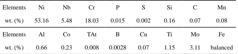
The base material used in this investigation was IN718, the chemical composition
of which is given in Table 1. The bar of IN718 was firstly cut by wiring electronic
discharge machining (WEDM) and then mechanically polished to a surface roughness
a size of Φ20 mm × 1 mm were cleaned by a 5 minutes ultrasonic bath in acetone and
followed by a 5 minutes ultrasonic bath in ethanol.
2.2. Nanosecond laser irradiation
After the metallographic preparation, various microstructures were fabricated on
IN718 surfaces by laser irradiation using the Ytterbium nanosecond pulsed fiber laser
system (IPG photonics from Germany). The parameters of the laser system are shown
in Table 2.
Table 1 Chemical composition of IN718
Elements Ni Nb Cr P S Si C Mn
wt. (%) 53.16 5.48 18.03 0.015 0.002 0.16 0.07 0.08
Elements Al Co TAt B Cu Ti Mo Fe
[image:7.595.91.509.259.355.2]wt. (%) 0.66 0.23 0.008 0.0028 0.07 1.15 3.11 balanced
Table 2 Laser system parameters
Wavelength Average power Pulse duration Repetition rate Spot diameter Fluence
(nm) (W) (ns) (kHz) (μm) (J/cm2)
1064 0-20 50 20 60 0-35.38
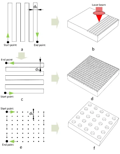
The polished samples placed on the working platform were irradiated by the
moving laser beam. As a result, the grooves or holes were produced on their surfaces
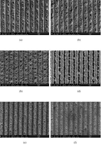
by the raster scanning of laser beam. Figs. 1(a) and (b) show the line pattern was formed
when laser beam began at the start point, with a zigzag scanning path, stopped at the
end point. As shown in Fig 1(c) and (d), the grid pattern was obtained if the laser trace
then rotated through 90° to scan by the same path. Additionally, according to the laser
scanning strategy shown in Fig. 1(e), the spot pattern with many holes was established
on the surface of IN718 shown in Fig. 1(f). Each hole was formed by many laser pulses
irradiation. The number of pulses N could be calculated by the following equation [30]:
𝑁 =𝜋Φ𝑓4𝑉 (3)
Where Φ and f are laser spot diameter and repetition rate, respectively. V is the
by 18 laser pulses irradiation. After laser treatment, surface morphology was
determined by surface pattern and the distance between the successive grooves and
holes. Besides, the profile of the ablated grooves and holes had a high affinity for laser
parameters such as laser scanning speed and average power. Five groups of experiments
(presented in Table 3) were carried out using the single variable method to
comprehensively investigate the effects of surface patterns (Group 1-3) and laser
parameters (Group 4-5) on nanosecond-laser-inscribed surface morphology and
wettability of IN718 material. The whole irradiated area on all samples surfaces was
confined as a square with the size of 10 mm×10 mm. Laser irradiation experiments
were performed in air under the atmospheric conditions.
2.3. Surface measurement and characterization
The effects of laser treatment on surface morphology were studied by means of
SEM (FEI, Quanta 250 FEG). A white light confocal microscope (Zeiss CSM700) was
used to measure surface average roughness (Ra). Groove depth and width as well as 3D
profile of the samples were measured by a laser confocal scanning microscope
(Olympus, LEXT-OLS4000). The contact angles were measured by sessile drop
technique using a 3 μL distilled water droplet at the room conditions of the constant
temperature 25℃ and air humidity around 50%. The contact angles were recorded
when the dispensed droplet reached the equilibrium state on the surfaces. For the needs
of date reliability and result reproducibility, at least five different locations were
Figure 1. Schematic explanation of laser performance for producing grooves or holes on IN718 surface. (a), (c) and (e) were the path of laser beam from the top view. (b), (d) and (f)
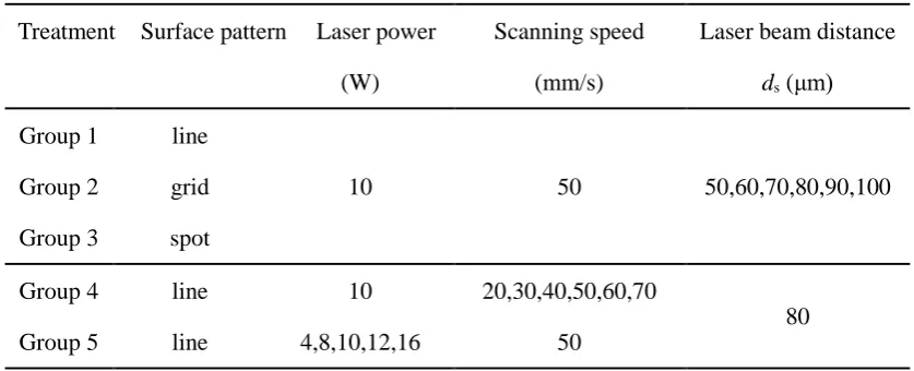
Table 3 Important experimental details for each group of laser treatment
Treatment Surface pattern Laser power Scanning speed Laser beam distance
(W) (mm/s) ds (μm)
Group 1 line
10 50 50,60,70,80,90,100
Group 2 grid Group 3 spot
Group 4 line 10 20,30,40,50,60,70
80
Group 5 line 4,8,10,12,16 50
3. Results and discussion
3.1. Analysis of surface morphology
The surface topographic characterization clearly illustrated the effect of laser
ablation on the surface morphology of IN718 material. Evidently, the modified surface
morphology varied when different laser processing strategies were performed on the
prepared samples. In this section, SEM and 3D confocal images of the laser ablated
surfaces are comprehensively discussed to investigate the effects of various
laser-inscribed patterns and laser parameters on surface morphology.
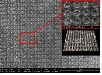
(c) Spot pattern
Figure 2. SEM images of different surface micropatterns: (a) Line pattern (b) Grid pattern (c) Spot pattern. The insets are corresponding magnified SEM and 3D confocal images.
3.1.1. Effect of laser-inscribed patterns on surface morphology
After laser treatment, three types of microstructures were fabricated on IN718
surfaces, and their corresponding surface SEM images and 3D profiles are shown in
Fig. 2. The width and depth of the laser ablated grooves for line pattern (except the
sample with distance of 50 μm) are 334.6 μm and 232.9 μm, respectively. It is
clearly noted that the IN718 surfaces underwent the processes of melting, splashing and
freezing in sequence. Also, we can see that the debris (i.e. redeposited materials) was
covered by large numbers of micro and nanoscale particles, which can alter surface
morphology in comparison to the pristine polished surfaces. This is probably caused by
rapid cooling and solidification of splashing material. This phenomenon can be
specially observed from the surface with spot pattern as shown in Fig. 2(c). However,
the diameter and depth of the laser ablated holes for spot pattern are 481.3 μm and 4
0.5 μm, respectively. Among these three patterns, the surfaces with grid pattern had
the greatest impact on surface morphology since this kind of structure (Fig. 2(b)) was
the most complicated one and the proportion of laser ablated area was the largest.
Besides, the distance between successive grooves or holes also influenced the
surface morphology. In this study, the distance was set to be 50, 60, 70, 80, 90 and 100
μm, respectively. Previous literature reported that the changes of surface morphology
conclusion, surface roughness of the samples was measured using a white light confocal
microscopy.
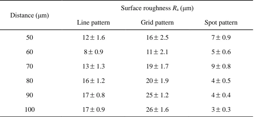
According to Table 4, it is confirmed that the grid pattern experienced the most
serious laser ablation because the values of surface roughness for grid pattern were
relatively higher than that for line pattern. The surfaces with spot pattern exhibited the
minimum roughness values, which meant that this micro/nanostructure had the smallest
impact on surface morphology. The reasons may lie in less molten materials resolidified
on the brim of laser ablated holes, and a large presence of untreated surface was visible
[image:12.595.94.507.306.496.2]as shown in Fig. 2(c).
Table 4 Surface roughness of patterned samples with various distance
Distance (μm) Surface roughness Ra (μm)
Line pattern Grid pattern Spot pattern
50 121.6 162.5 70.9
60 80.9 112.1 50.6
70 131.3 191.7 90.8
80 161.2 201.9 40.5
90 170.8 251.2 40.4
100 170.9 261.6 30.3
However, it can be found, with the increase of distance, that surface roughness did
not show a downward trend as described in previous investigation [41] but presented
an earlier decrease and later increase trend on the whole. In this study, we propose two
main reasons to elucidate the discrepancies. On the one hand, it is perhaps attributed to
the high laser power that led to the absence of ripple structures normally found on the
laser ablated surface. The high magnification picture (Fig. 3(a)) shows that, when the
laser beam with higher power was performed on the surfaces, the huge amount of
thermal energy accumulated at a localized region and the melting material may slightly
move to form layer-by-layer structures before resolidification. The arbitrary
accumulation of this kind of structure made the surface more rough, particularly for
of the groove, but no distinct grooves were observed on laser ablated surface when the
laser beam with the smallest distance of 50 μm as shown in Fig. 3. This is because the
diameter of laser beam was greater than the interval width of grooves or holes, which
resulted in overlapped section (shown in Fig. 4). In this paper, the redeposited materials
covered on the brim of untreated zone are termed as ridges. Due to the small interval of
laser beam, the existing overlapped section would make wavy structures and there were
no distinct grooves on the laser treated surface, which could be verified by Fig. 3(b).
As a result, the forest of entangled and compacted microstrcutures made the surface
with the distance of 50 μm much rougher than the one with the distance of 60 μm. With
the growth of distance, the overlapped effect lessened and the treated surface exhibited
evident grooves as shown in Fig. 2(a). Consequently, the roughness value then
increased when the distance went up in our experiment.
[image:13.595.109.492.357.527.2]
(a) (b)
Figure 3. High magnification SEM image (a) and 3D profile (b) of line pattern with distance of 50 μm.
[image:13.595.215.381.589.726.2]3.1.2. Effect of laser scanning speed on surface morphology
(a) (b)
(b) (d)
[image:14.595.101.499.106.683.2](e) (f)
(a) (b)
[image:15.595.98.500.76.431.2](c)
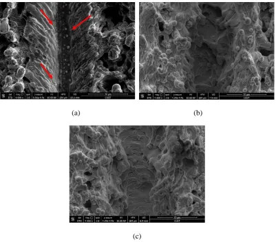
Figure 6. High magnification SEM images of surface structures with laser scanning speed: (a) 20 mm/s (b) 50 mm/s (c) 70 mm/s
Fig. 5 shows SEM images of surface structures under different laser scanning
speed. With the increase of laser scanning speed, surface morphology changed
significantly, which was caused by different number of pulses preformed at per unit
lengths of the groove. Due to more laser pulses, low scanning speed led to more molten
materials and smaller particles on the resolidified materials. The molten materials could
easily move into the fabricated grooves and resolidified in the bottom (along the
direction of the red arrow shown in Fig. 6(a)). This is the reason why the depth of
groove was smaller for laser scanning speed 20 mm/s than that for 50 mm/s. When the
speed went up further to 70 mm/s, less number of pulses was performed at per unit of
the groove. Hence, the depth of groove decreased for high scanning speed. However,
the width of the grooves for various scanning speed witnessed little change in this
there were more cracks created on the bottom of the ablated grooves. The reason for
this phenomenon could be related to the effect of thermal expansion and cold
contraction. The high laser scanning speed resulted in severe such effect, so more cracks
and particles would be produced in the laser ablated area. On the whole, when the laser
scanning speed was 50 mm/s, the surface morphology was changed the most degree,
which could be verified in Table 5.
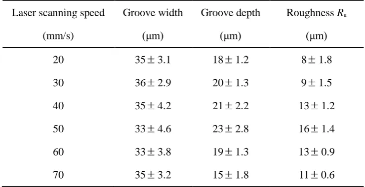
Figs. 5, 6 and Table 5 indicated that laser scanning speed had a great impact on
surface morphology and surface roughness due to the factors of groove depth and width
as well as the thermal expansion and cold contraction effect. In order to fabricate
optimum laser-inscribed surface with best wetting property, laser scanning speed should
[image:16.595.112.482.353.543.2]be set rationally.
Table 5 Details of surface structures created by various laser scanning speed Laser scanning speed
(mm/s)
Groove width (μm)
Groove depth (μm)
Roughness Ra
(μm)
20 353.1 181.2 81.8
30 362.9 201.3 91.5
40 354.2 212.2 131.2
50 334.6 232.8 161.4
60 333.8 191.3 130.9
70 353.2 151.8 110.6
3.1.3. Effect of laser average power on surface morphology
Apart from laser scanning speed, laser average power is another important factor
influencing the surface topology. Corresponding SEM pictures and surface data of laser
(a) (b)
(b) (d)
[image:17.595.98.501.77.601.2](e)
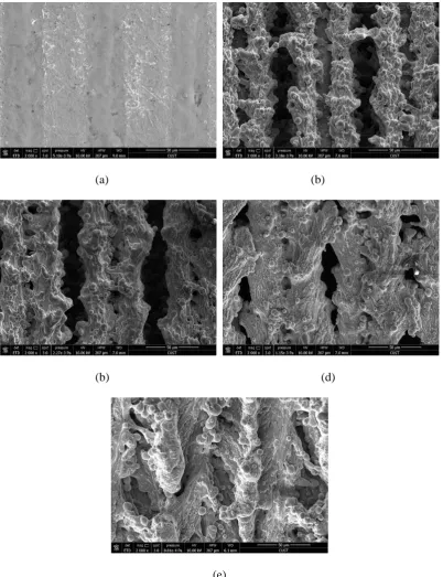
Figure 7. SEM images of surface structures with various laser average power: (a) 4 W (b) 8 W (c) 10 W (d) 12 W (e) 16 W
Table 6 Details of surface structures created by different laser average power Laser average power
(W)
Groove width (μm)
Groove depth (μm)
Roughness Ra
[image:17.595.117.480.705.753.2]4 381.2 50.5 10.6
8 352.8 161.5 111.1
10 334.6 232.9 161.3
12 - - 150.9
16 - - 111.0
As can be seen from Fig. 7(a) that when laser average power was set at 4 W, very
few materials redeposited on the edges of laser ablated grooves and the depth of the
grooves were much smaller in comparison to higher laser power. Also, a large amount
of untreated IN718 surface was visible in this case. It can be inferred that the lower
laser average power resulted in slight changes of surface morphology, which also can
be verified by the smallest surface roughness value of 10.6 μm as shown in Table 6.
With the increase of the laser average power (8 W and 10 W), the width of the laser
ablated groove witnessed a slight decrease. However, the depth of the laser ablated
grooves deepened. Especially, when laser power was 10 W shown in Fig. 7(c), the large
volume of splashed molten materials resolidified on the untreated area and almost
covered the whole untreated surface, which resulted in a rougher surface. It also can be
proved from the largest roughness value of 161.3 μm shown in Table 6. However, it
is not meant that the higher laser average power, the rougher surface can be obtained.
Fig. 7(d) and (e) show that when laser power was set at 12 W and 16 W, the molten
materials would slightly move before resolidification. So the width of the grooves
would diminish as well as the surface roughness value. The reason of above mentioned
phenomenon might be that more material would be ablated from the groove and then
cover the previous groove at higher laser average power. As a result, there were no
grooves formed on the as-prepared surfaces.
It also can be deduced from Fig. 7 and Table 6 that laser average power had a great
impact on surface morphology and surface roughness. In order to obtain surface with
desired property, the laser average power also should be optimized.
3.2. Analysis of surface wettability
[image:18.595.114.482.74.190.2]the process of WCA measurement. A 3 μL droplet of distilled water was placed on the
untreated and laser treated samples surfaces in air at atmospheric conditions. Then a
side view of droplet was automatically captured and calculated by the installed software
as shown in Fig. 9. Before and after laser treatment, the WCA of polished IN718 sample
surface was measured every day and the mean value was 45.2° with the standard
deviation of 0.6°. Directly after laser irradiation, the WCA witnessed a considerable
change over time. The investigation of the influence of surface patterns on surface
[image:19.595.91.505.254.336.2]wettability has been presented as follow:
[image:19.595.185.412.539.758.2]Figure 8. The process of placing the distilled water droplet
Figure 9. Contact angle measurement
(b)
[image:20.595.186.413.71.480.2](c)
Figure 10. Evolution of contact angle over time for (a) line pattern (b) grid pattern (c) spot pattern
Table 7 Average apparent contact angle and rolling angle of the treated surfaces Distance
(μm)
Line pattern Grid pattern Spot pattern
WCA (°) RA (°) WCA (°) RA (°) WCA (°) RA (°)
50 144.51.1 23.5 1.5
150.60.9 9.71.2 132.33.6 435.6
60 141.60.8 28.2 1.3
147.71.3 15.60.9 125.55.2 654.3
[image:20.595.90.504.588.756.2]1.6 80 147.60.9 15.7
2.2
153.51.0 7.61.1 120.94.6 708.2
90 149.31.0 12.6 1.8
155.30.8 7.31.3 116.65.3 -
100 152.31.2 8.81.1 156.81.1 6.50.8 110.35.6 -
It is essential to understand the effect of microstructures with respect to the contact
angles. Fig. 10 depicts the evolution of WCAs as a function of time for three types of
surface patterns. Table 7 presents the stable WCAs and the corresponding RAs.
Time dependency of WCA for line-patterned surfaces has been shown in Fig. 10(a).
Directly after laser ablation, the WCAs declined dramatically and all the sample
surfaces were highly hydrophilic. This phenomenon was well observed within 4 days
after laser processing. It was unable to calculate WCAs since the water droplet almost
completely penetrated into the grooves. The reason for this phenomenon was that the
laser treated surface just after laser radiation was highly nonequilibrium, contained
many surface defects and possessed a very high surface energy. Thus, this surface was
characterized by the superhydrophilicity. 5 days later, the WCAs grew up gradually to
arrive at 100°, which exhibited hydrophobic property. Beyond 15 days, except for the
distance of 70 μm, the WCAs continued to increase and reach in the range of 130°-140°.
Samples surfaces became much more hydrophobic. Beyond a certain period (20 days
here), this increasing trend stopped. The steady WCA was noticed in the following days.
All the WCAs reached to above 140° and the maximum WCA for line-patterned surface
was 152.31.2° with the RA of 8.8 1.1°, which exhibited a superhydrophobic
character. From Fig. 10(a), it also can be observed that the developments of WCA over
time were different due to the various distance between the successive grooves on line
patterned surfaces. Thus there were discrepancies for the final steady WCAs. It can be
deduced that there is a possible link between surface roughness and the final steady
WCA. Generally, the rougher surface was, the larger WCA was. In order to get desired
successive grooves should be selected reasonably.
The time evolutions of WCAs for grid-patterned and spot-patterned surfaces are
shown in Fig. 10(b) and 10(c), respectively. Immediately after the laser treatment,
WCAs for these two kinds of surfaces maintained at almost 0° for 4-5 days. After that,
the values exhibited a significant increase trend to reach above 120°. Beyond a certain
period (25 days here), the curves of WCA presented no major changes. For samples
with grid pattern, except for distance of 60 μm, all the surfaces exhibited
superhydrophobic character with the steady WCAs above 150° and RA below 10°. The
maximum value even reached 156.81.1° with the RA of just 6.50.8°. Samples with
spot pattern showed hydrophobic character with the contact angles above 90°. However,
the maximum WCA was only 140.82.8° and none RA was under 10°. Therefore, even
after laser treatment, the spot-patterned surfaces cannot presente superhydrophobic
property.
The results suggest that the changes of surface wettability can be related to the
modification of surface topography. It can be explained either by Wenzel model [19] or
by Cassie-Baxter model [20]. When the Wenzel’s state occurs, the intrinsic surface
wettability is enhanced by roughness: a hydrophilic surface becomes more hydrophilic
with the growth of roughness, and a hydrophobic surface becomes more hydrophobic
with an increase of roughness. Since the IN718 surface is initially hydrophilic, the
performed nanosecond laser ablation would make it more hydrophilic with the smaller
contact angle. In this study, it is well pronounced that the immediate improvement of
hydrophilicity was observed at the first moments following laser treatment. That means
the influence of surface topology was more preponderant and the Wenzel model was
more likely.
However, the time dependency of WCA cannot be explained by surface
morphology because surface microstructure did not change over time. Laser modified
hydrophobic surfaces were reported elsewhere in previous literatures and the effect of
surface chemistry seems more possible to explain such a change [42-43]. After laser
treatment, the surface hydrophobicity gradually improved due to the possible change of
constant WCAs were obtained. In this case, it is more likely that air pockets were
trapped underneath the liquid droplet as described by Cassie-Baxter model,which
contributed to the hydrophobic or superhydrophobic surfaces exhibiting the larger
WCA and smaller RA.
3.3. Analysis of surface chemical composition
In order to verify above mentioned assumption, the elementary analysis of surface
chemistry was carried out by XPS experiments when contact angles stabilized. The
surface chemical compositions before and after laser irradiation were compared to
evidence the possible effect of laser ablation on surface chemistry.
(a) (b)
[image:23.595.93.498.290.638.2]
(c) (d)
Figure 11. XPS spectra of IN718 surface (a) untreated surface (b) line pattern (c) grid pattern (d) spot pattern
The results of surface chemical compositions are shown in Fig. 11. Before laser
treatment, the IN718 surface presented a carbon content of 28.2%, while after laser
grid pattern, and spot pattern, respectively. The result indicates that after laser treatment
a change in surface chemistry with the increase of carbon content clearly occurred. Thus,
it can be verified from XPS analysis that the time dependency of surface wettability
after laser treatment was due to the change of surface chemical compositions, especially
the proportion of carbon content.
According to previous literature [39], although carbonization reaction and
oxidation reaction would be inevitable to occur during laser processing since the
experiments were conducted under the ambient air, the main reason why the laser
treated surfaces exhibited superhydrophilic state just after the interaction between laser
radiation and the substrate could be that such surface was highly nonequilibrium,
contained a lot of surface defects and thus possessed a very high surface energy and
was therefore characterized by the superhydrophilicity. For surface property, the
wettability is highly sensitive to surface contaminations [44]. With the evolution of
exposure time under ambient air, the original laser treated hydrophilic surfaces turned
to be hydrophobic or superhydrophobic. Recentinvestigations show that the time
dependency of surface wettability was related to the spontaneous adsorption of airborne
hydrocarbon contaminations on the as-prepared surface [21, 39]. As a result, the
proportion of carbon content on the surface would increase. Aria [45] and Liu [46] both
have carried out independently further experiments in order to verify this conclusion.
The surface chemistry was investigated by XPS for the samples with
superhydrophobicity, before/after thermal annealing treatment, UV-O3 treatment, and
before/after Ar+-etching in vacuum and re-exposure under ambient air [45-46].
In our work, the influence of surface morphology on wettability was formed
directly after laser treatment and would not change over time. The time evolution of
surface wettability of laser treated surfaces was attributed to the change of surface
chemical compositions. Generally speaking, surface morphology and surface chemistry
are the combined factors to obtain thermodynamically stable superhydrophobic surface
on IN718 samples.
4. Conclusions
in the open air. In order to investigate surface morphology and surface wettability by
laser treatment, three types of microstructures (line, grid and spot pattern) were
fabricated on the samples surfaces. The results show that surface morphology and
surface roughness can be controlled experimentally by varying surface pattern and laser
parameters. These variations are accompanied by modifications of surface wettability.
Directly after laser treatment, the contact angle declined dramatically and the surfaces
became more hydrophilic, which can be explained by the Wenzel model. The WCAs of
the laser treated surfaces witnessed a time dependency phenomenon due to the change
of surface chemical compositions, especially the carbon content. As a result, several
laser treated surfaces exhibited superhydrophobic property. We attributed the
laser-induced change of the wetting behavior to the combined both surface morphology and
surface chemical compositions.
Acknowledgements
The authors wish to acknowledge the technical supports of Tianjin University,
University of Warwick, and Changchun University of Science and Technology. The
authors are grateful for the financial support from National Natural Science
Foundations of China [Nos.51405333, 51675371, 51675376 and 51675367], China-EU
H2020 FabSurfWAR project (Nos.S2016G4501 and 644971), and the State Key
Laboratory of Special Vehicles and Their Drive System Intelligent Manufacturing.
References:
[1] K. Venkatesan, R. Ramanujam, P. Kuppan, Parametric modeling and optimization
of laser scanning parameters during laser assisted machining of Inconel 718, Opt.
Laser Technol. 78 (2016) 10-18.
[2] K.H. Song, K. Nakata, Microstructural and mechanical properties of
friction-stir-welded and post-heat-treated Inconel 718 alloy, J. Alloy. Compd. 505 (2010)
144-150.
[3] M. Anderson, R. Patwa, Y.C. Shin, Laser-assisted machining of Inconel 718 with
an economic analysis, Int. J. Mach. Tools Manuf. 46 (2006) 1879-1891.
[4] Z. Wang, K. Guan, M. Gao, X. Li, X. Chen, X. Zeng, The microstructure and
Compd. 513 (2012) 518-523.
[5] H. Attia, S. Tavakoli, R. Vargas, V. Thomson, Laser-assisted high-speed finish
turning of superalloy Inconel 718 under dry conditions, CIRP Ann-Manuf. Technol.
59 (2010) 83-88.
[6] Z.Y. Wang, K.P. Rajurkar, J. Fan, S. Lei, Y.C. Shin, G. Petrescu, Hybrid machining
of Inconel 718, Int. J. Mach. Tools Manuf. 43 (2003) 1391-1396.
[7] B. Bhushan, Y.C. Jung, Natural and biomimetic artificial surfaces for
superhydrophobicity, self-Cleaning, low adhesion, and drag reduction, Prog. Mater.
Sci. 56 (2011) 1-108.
[8] Z. Yuan, J. Xiao, C. Wang, J. Zeng, S. Xing, J. Liu, Preparation of a
superamphiphobic surface on a common cast iron substrate, J. Coat. Technol. Res.
8 (2011) 773-777.
[9] K. Ellinas, A. Tserepi, E. Gogolides, From superamphiphobic to amphiphilic
polymeric surfaces with ordered hierarchical roughness fabricated with colloidal
lithography and plasma nanotexturing, Langmuir 27 (2011) 3960-3969.
[10] K. Paso, T. Kompalla, N. Aske, H.P. Rønningsen, G. Øye, J. Sjoblom, Novel
surfaces with applicability for preventing wax deposition: a review, J. Dispersion
Sci. Technol. 30 (2009) 757-781.
[11] Y.C. Sheen, Y.C. Huang, C.S. Liao, H.Y. Chou, F.C. Chang, New approach to
fabricate an extremely super-amphiphobic surface based on fluorinated silica
nanoparticles, J. Polym. Sci. Part B: Polym. Phys. 46 (2008) 1984-1990.
[12] K. Liu, Y. Tian, L. Jiang, Bio-inspired superoleophobic and smart materials:
design, fabrication, and application, Prog. Mater. Sci. 58 (2013) 503-564.
[13] C.T. Hsieh, J.M. Chen, R.R. Kuo, T.S. Lin, C.F. Wu, Influence of surface
roughness on water- and oil-repellent surfaces coated with nanoparticles, Appl.
Surf. Sci. 240 (2005) 318-326.
[14] V. Kumar, J. Pulpytel, H. Rauscher, I. Mannelli, F. Rossi, F.A. Khonsari,
Fluorocarbon coatings via plasma enhanced chemical vapor deposition of
1H,1H,2H,2H-perfluorodecyl acrylate-2, morphology, wettability and antifouling
[15] Z. Cui, L. Yin, Q. Wang, J. Ding, Q. Chen, A facile dip-coating process for
preparing highly durable superhydrophobic surface with multi-scale structures on
paint films, J. Colloid Interface Sci. 337 (2009) 531-537.
[16] S. Srinivasan, S.S. Chhatre, J.M. Mabry, R.E. Cohen, G.H. McKinley. Solution
spraying of poly (methyl methacrylate) blends to fabricate microtextured,
superoleophobic surfaces, Polymer 52 (2011) 3209-3218.
[17] K. Zhao, K.S. Liu, J.F. Li, W.H. Wang, L. Jiang. Superamphiphobic CaLi-based
bulk metallic glasses, Scr. Mater. 60 (2009) 225-227.
[18] M. Psarski, J. Marczak, J. Grobelny, G. Celichowski, Superhydrophobic surface
by replication of laser micromachined pattern in epoxy/alumina nanoparticle
composite, J. Nanomater. 2 (2014) 105-119.
[19] R. N. Wenzel, Resistance of solid surfaces to wetting by water, J. Ind. Eng.
Chem. 28 (1936) 988-994.
[20] A.B.D. Cassie, S. Baxter, Wettability of porous surfaces, Trans. Faraday Soc. 40
(1944) 546-551.
[21] L. B. Boinovich, A. M. Emelyanenko, A. S. Pashinin, C. H. Lee, J. Drelich, Y. K.
Yap, Origins of thermodynamically stable superhydrophobicity of Boron Nitride
nanotubes coatings, 28 (2012), 1206-1216.
[22] X. Yao, Y. L. Song, L. Jiang, Applications of bio-inspired special wettable surfaces,
Adv. Mater. 23 (2013) 719-734.
[23] N. A. Ivanova, G. I. Rutberg, A. B. Philipchenko, Enhancing the
superhydrophobic state stability of chitosan-based coatings for textiles, Macromol.
Chem. Phys. 214 (2013), 1515-1521.
[24] D. Quéré, Non-sticking drops, Rep. Prog. Phys. 68 (2005) 2495-2532.
[25] Y.Q. Tang, Q. H. Zhang, X. L. Zhan, F. Q. Chen, Superhydrophobic and anti-icing
properties at overcooled temperature of a fluorinated hybrid surface prepared via
a sol-gel process, Soft Matter, 11 (2015) 4540-4550.
[26] Z. L. Jiang, S. Y. Fang, C. S. Wang, H. P. Wang, C. C. Ji, Durable
polyorganosiloxane superhydrophobic films with a hierarchical structure by
[27] T. Hang, A. Hu, H. Ling, M. Li, D. Mao, Super-hydrophobic nickel films with
micro-nano hierarchical structure prepared by electrodeposition, Appl. Surf. Sci.
256 (2010) 2400-2404.
[28] Y. Liu, X. Yin, J. Zhang, Y. Wang, Z. Han, L. Ren, L, Biomimetic hydrophobic
surface fabricated by chemical etching method from hierarchically structured
magnesium alloy substrate, Appl. Surf. Sci. 280 (2013) 845-849.
[29] N.G. Semaltianos, W. Perrie, P. French, M. Sharp, G. Dearden, K.G. Watkins,
Femtosecond laser surface texturing of a nickelbased superalloy, Appl. Surf. Sci.
255 (2008) 2796-2802.
[30] B. Wu, M. Zhou, J. Li, X. Ye, G. Cai, Superhydrophobic surfaces fabricated by
microstructuring of stainless steel using a femtosecond laser, Appl. Surf. Sci. 256
(2009) 61-66.
[31] G. Dumitru, V. Romano, Laser microstructuring of steel surfaces for tribological
applications, Appl. Phys. A 70 (2000) 485-487.
[32] J. Li, L. Yan, H. Li, J. Li, F. Zha, Z. Lei, A facile one-step spray-coating process
for the fabrication of superhydrophobic attapulgite coated mesh used in oil/water
separation, RSC Adv. 5 (2015) 53802-53808.
[33] F. Mcklich, A.F. Lasagni, C. Daniel, Laser interference metallurgy-using
interference as a tool for micro/nano structuring, Int. J. Mater. Res. 10 (2006)
1337-1344.
[34] L. B. Boinovich, A. M. Emelyanenko, A. D. Modestov, A. G. Domantovsky, K. A.
Emelyanenko, Synergistic effect of superhydrophobicity and oxidized layers on
corrosion resistance of aluminum alloy surface textured by nanosecond laser
treatment, ACS Appl. Mater. Interfaces, 7 (2015) 19500-19508.
[35] T. C. Chen, H. T. Liu, H. F. Yang, W. Yan, W. Zhu, H. Liu. Biomimetic fabrication
of robust self-assembly superhydrophobic surfaces with corrosion resistance
properties on stainless steel substrate. RSC Adv. 6 (2016) 43937-43949.
[36] A. M. Emelyanenko, F. M. Shagieva, A. G. Domantovsky, L. B. Boinovich,
Nanosecond laser micro- and nanotexturing for the design of asuperhydrophobic
Sur. Sci. 332 (2015) 513-517.
[37] A. Milionis, D. Fragouli, F. Brandi, L. Liakos, S. Barroso, R. Ruffilli, A.
Athanassiou, Superhydrophobic/superoleophilic magnetic elastomers by
laserablation, Appl. Surf. Sci. 351 (2015) 74-82.
[38] D. V. Ta, A. Dunn, T. J. Wasley, R. W. Kay, J. Stringer, P. J. Smith, C. Connaughton,
J. D. Shephard, Nanosecond laser textured superhydrophobic metallic surfaces and
their chemical sensing applications. Appl. Surf. Sci. 357 (2015) 248-254.
[39] L. B. Boinovich, A. M. Emelyanenko, K. A. Emelyanenko, A. G. Domantovsky,
A. A. Shiryaev, Comment on “Nanosecond laser textured superhydrophobic
metallic surfaces and their chemical sensing applications” by Duong V. Ta,
Andrew Dunn, Thomas J. Wasley, Robert W. Kay, Jonathan Stringer, Patrick J.
Smith, Colm Connaughton, Jonathan D. Shephard (Appl. Surf. Sci. 357 (2015)
248-254), Appl. Surf. Sci. 379 (2016) 111-113.
[40] M.L. Wu, C.Z Ren, Active control of the anisotropic wettability of the carbon fiber
reinforced carbon and silicon carbide dual matrix composites (C/C-SiC), Appl.
Surf. Sci. 327 (2015) 424-431.
[41] C. Yang, X. Mei, Y. Tian, D. Zhang, Y. Li, X. Liu, Modification of wettability
property of titanium by laser texturing, Int. J. Adv. Manuf. Technol. (2016) 1-8.
[42] A.M. Kietzig, M.N. Mirvakili, S. Kamal, P. Englezos, S.G. Hatzikiriakos, Cassie
to Wenzel wetting transitions on femtosecond laser-patterned pure metallic
substrates, J. Adhes. Sci. Technol. 25 (2011) 2789-2809.
[43] P. Bandoki, S. Valette, E. Audouard, S. Benayoun, Time dependency of the
hydrophilicity and hydrophobicity of metallic alloys subjected to femtosecond
laser irradiations, Appl. Surf. Sci. 273 (2013) 399-407.
[44] Z. T. Li, Y. J. Wang, A. Kozbial, G. Shenoy, F. Zhou, R. McGinley, P. Ireland, B.
Morganstein, A. Kunkel, S. P. Surwade, L. Li, H. T.Liu, Effect of airborne
contaminants on the wettability of supported graphene and graphite, Nat. Mater.
12 (2013) 1-7.
[45] A. I. Aria, P. R. Kidambi, R. S. Weatherup, L. Xiao, J. A. Williams, S. Hofmann,
exposure, J. Phys. Chem. C 120 (2016) 2215-2224.
[46] P. Liu, L. Cao, W. Zhao, Y. Xia, W. Huang, Z. L. Li, Insights into the
superhydrophobicity of metallic surfaces prepared by electrodeposition involving
spontaneous adsorption of airborne hydrocarbons, Appl. Surf. Sci. 324 (2015)