University of Warwick institutional repository:
http://go.warwick.ac.uk/wrap
A Thesis Submitted for the Degree of PhD at the University of Warwick
http://go.warwick.ac.uk/wrap/55425
This thesis is made available online and is protected by original copyright.
Please scroll down to view the document itself.
Rotaxane Synthesis via the ‘Threading Followed by
Stoppering’ Approach.
by
Jennifer Yates
A thesis submitted in partial fulfilment of the requirements for the
degree of
Doctor of Philosophy in Chemistry
University of Warwick, Department of Chemistry
I
Contents
List of Figures ... V
List of Schemes ... VIII
List of Tables ...XV
Acknowledgments ... XVI
Declaration ... XVII
Abstract ... XVIII
Abbreviations ...XX
Chapter 1 Introduction ... 1
1.
Supramolecular Chemistry ... 2
1.2
Rotaxanes ... 3
1.3
Early Methods of Synthesis ... 3
1.4
Self Assembly Approaches to Rotaxane Synthesis ... 4
1.5
Non-Metal Templates ... 5
1.5.1
Hydrogen bonding ... 5
1.5.2
π-π Interactions ... 7
1.5.3
Anion Template ... 10
1.5.4
Hydrophobic Interactions ... 12
1.6
Methods of Formation ... 13
II
1.6.2 Template-Directed Synthesis
via
the Clipping Approach ... 17
1.6.3
Self-Assembly Approach
via
Slipping ... 18
1.6.4
Threading Followed by Swelling Approach ... 19
1.7
Potential Uses and Scientific Interest ... 20
1.7.1
Valves ... 20
1.7.2
Wheels... 21
1.7.3
Molecular Switches ... 21
1.8
Transition Metal Strategy ... 25
1.9
Summary and Outlook ... 28
Chapter 2 - Synthesis of [2] and [3]Rotaxanes Using a ‘Diels-Alder Approach to
Threading Followed by Stoppering’. ... 29
2.
Synopsis ... 30
2.1
Introduction ... 32
2.2
Synthesis of [n]rotaxanes with Ammonium Ion Binding Motifs ... 33
2.2.1
Higher Order Rotaxanes ... 39
2.2.2
Synthesis of a Short Diels-Alder Stopper Rotaxane ... 43
2.2.3
Investigating the Stopper Size ... 45
2.3
Perimidine Benzimidazole Binding Motif ... 50
2.3.1
Synthesis of Perimidine Pseudorotaxanes and Rotaxanes ... 53
2.4
Bis
Pyridinium Functionalised Rotaxanes ... 60
III
2.6
General Experimental ... 71
2.6.1
Experimental Section ... 72
Chapter 3 - Synthesis of [n]Rotaxanes using CuAAC ‘Click Chemistry’ and the
Diels-Alder Approach to ‘Threading followed by Stoppering’... 124
3.
Synopsis ... 125
3.1
Introduction ... 126
3.1.1 The Cu(I)-Catalysed Terminal Alkyne-Azide 1,3-Dipolar Cycloaddition
(CuAAC Reaction). ... 126
3.1.2 ‘CuAAC’ in Rotaxane Formation ... 127
3.2
Results and Discussion ... 128
3.2.1
Synthesis of Pseudorotaxanes Using ‘CuAAC Click Chemistry’. .... 128
3.3
Synthesis of Rotaxanes Using ‘CuAAC Click Chemistry’ and the
Diels-Alder Reaction ... 132
3.4
Synthesis of Higher Order Rotaxanes Using ‘CuAAC Click Chemistry’
139
3.5
Research into the Synthesis of Multiple Component Rotaxanes ... 142
3.6
Synthesis of
Bis
triazole Ammonium Threads Using ‘Click Chemistry’
153
3.7
Synthesis of Rotaxanes in a One Pot Method Using ‘CuAAC Click
Chemistry’ ... 160
3.8
Conclusion ... 165
IV
Chapter 4 - Synthesis of [2]Pseudorotaxanes and [2]Rotaxanes Using Novel
Macrocycles. ... 225
4.
Synopsis ... 226
4.1
Introduction ... 227
4.2
Synthesis of Novel 23 Atom Cavity Macrocycles. ... 230
4.3
Threading of the 23 Atom Macrocycle with Dialkylammonium Salts . 234
4.4
Synthesis of Dibenzo-23-crown Macrocycle. ... 238
4.5
Pseudorotaxane Formation with Novel 23 Atom Macrocycles and
Triazole Binding Templates ... 242
4.7
Conclusion ... 246
4.8
Experimental ... 247
Chapter 5 ... 263
5.1
Conclusion ... 263
Chapter 6 ... 265
6.1
References ... 265
Appendix ... 281
V
List of Figures
Figure 1.1 Nomenclature of pseudorotaxanes and rotaxanes. ... 3
Figure 1.2 Schematic representations of self assembly methods toward the synthesis of rotaxanes. ... 4
Figure 1.3 [3]Rotaxane containing two secondary ammonium ion binding sites. ... 6
Figure 1.4 Stoddart [2]rotaxane 1.10 with a DNP binding site and CBPQT4+ macrocycle. .... 8
Figure 1.5 Becher group [2]rotaxane with two TTF units and a CBPQT4+ macrocycle. ... 8
Figure 1.6 Loeb branched [n]rotaxane. ... 9
Figure 1.7 Schematic of the ‘slipping’ protocol. ... 19
Figure 1.8 A pH switchable molecular switch. ... 23
Figure 1.9 Schematic representation of the active metal template protocol. i) Metal addition; ii) Complexation and covalent bond formation; iii) Demetallation and [2]rotaxane formation. ... 26
Figure 2.1 Bisbenzimidazole and perimidine benzimidazole binding templates. ... 30
Figure 2.2 Unsymmetrical [2]rotaxane 2.01 and symmetrical [2]rotaxane 2.02. ... 31
Figure 2.3 The Diels-Alder ‘stopper formation’ reaction. ... 33
Figure 2.4 Coupling reagents that can be used in esterification reactions. ... 35
Figure 2.5 1H NMR (400 MHz, CD3CN, 300K) stacking plot of i) DB24C8; ii) [2]rotaxane 2.13 and iii) Comparison thread 2.19. ... 39
Figure 2.6 1H NMR (400 MHz, CD3CN, 300K) stacking plot of i) DB24C8; ii) [3]rotaxane 2.26 and iii) Comparison thread 2.30. ... 43
Figure 2.7 1H NMR spectra of a) [2]Pseudorotaxane 2.46 in DMSO-d6, RT; b) [2]Pseudorotaxane 2.46 in DMSO-d6, 40˚C, 2 weeks; c) [2]Pseudorotaxane 2.46 in DMSO-d6, 40˚C, 1 month. ... 49
Figure 2.8 The bisbenzimidazole template. ... 51
VI
Figure 2.10 The three phenalenyl redox species and the isoelectronic 1,3-diazaphenalenecompound. ... 53
Figure 2.11 Solid state structure side on view of [2]pseudorotaxane 2.53 showing hydrogen bonding between the thread NHs and crown ether oxygens. C white; O red; N blue; H pale blue. ClO4 counter ions have been removed for clarity. ... 55
Figure 2.12 Solid state structure of [2]pseudorotaxane 2.56 showing the interlocked nature of crown and thread. Hydrogens have been omitted for clarity except the NH’s involved in hydrogen bonding interactions with the crown and ClO4 counter ions. C white; O red; N blue; Cl green. ... 57
Figure 2.13 Tautomerism of functionalised benzimidazole. ... 59
Figure 2.14 1,2-bis(pyridinium)ethane binding template. ... 60
Figure 2.15 1H NMR (400 MHz, CD3CN, 300K) stacking plot of i) DB24C8 ii) [2]Rotaxane 2.01 and iii) comparison thread 2.72. ... 64
Figure 2.16 Solid state structure of [2]rotaxane 2.01 in an orientation to highlight the pi stacking interactions and the endo stereochemistry of the imide stopper. Only the hydrogens of the Diels-Alder stopper are retained to emphasise the stereochemistry. C white; N blue; O red; H pale blue. ClO4 counter ions have been removed for clarity. ... 65
Figure 2.17 1H NMR (400 MHz, CD3CN, 300K) stacking plot of i) DB24C8 ii) [2]Rotaxane 2.02 and iii) Comparison thread 2.79. ... 69
Figure 3.1 Benyzlammonium triazole binding motif. ... 125
Figure 3.2 Hypothesized Catalytic Cycle for ‘CuAAC’ Reaction.150 ... 126
Figure 3.3 [2]Pseudorotaxane 3.10. ... 129
Figure 3.4 [2]Pseudorotaxane 3.14. ... 130
Figure 3.5 [2]Pseudorotaxane 3.17. ... 131
Figure 3.6 1H NMR spectra (400 MHz, CD3CN, 300K) stacking plot of; i) DB24C8; ii) [2]Rotaxane 3.30 and iii) Comparison thread 3.36. ... 137
Figure 3.7 1H NMR spectra (400 MHz, CDCl3, 300K) [3]Rotaxane 3.43. ... 141
VII
Figure 3.9 Open gate axle 3.52. ... 145Figure 3.10 1H NMR (400MHz, CD3CN, 300K) stacking plot of i) CBPQT 4+
; ii)
[2]Rotaxane 3.66 and iii) Comparison thread 3.67. ... 152
Figure 3.11 A view of the solid state structure of 3.66 highlighting the interlocked nature of
the [2]rotaxane and the endo stereochemistry of the Diels-Alder stopper adduct. Hydrogens
and minor disordered components have been removed for clarity. C white; O red, N blue.153
Figure 3.12 [2]pseudorotaxane 3.73. ... 155
Figure 3.13 Partial 1H NMR (400 MHz, CD3CN, 300K) stacking plot of i) DB24C8; ii)
[2]Pseudorotaxane 3.73 and iii) Comparisonthread 3.72. ... 156
Figure 3.14 1H NMR (400 MHz, CD3CN, 300K) i) DB24C8; ii) [2]Rotaxane 3.81 and iii)
ClO4- thread 3.84. ... 160
Figure 3.15 1H NMR (400 MHz, CD3CN, 300K) stacking plot of i) DB24C8 ii) [2]Rotaxane
3.89 and iii) Comparison thread 3.90. ... 162
Figure 3.16 1H NMR of [3]rotaxane 3.91 (400MHz, CDCl3, 300K). ... 164
Figure 4.1 Macrocycle 4.01 and 4.02. ... 226
Figure 4.2 Benzo-21-crown-7 binding studies with three ammonium binding templates. .. 228
Figure 4.3 [2]Rotaxane formed from a secondary dialkylammonium and a
pyrido-21-crown-7. ... 228
Figure 4.4 Synthesis of [2]rotaxane 4.07 via a RCM clipping strategy. ... 229
Figure 4.5 Loeb’s [2]pseudorotaxane 4.08 containing additional ionic interactions. ... 229
Figure 4.6 1H NMR Spectra (400 MHz, CD3CN, 300K) stacking plot i) Macrocycle 4.01; ii)
[2]Pseudorotaxane 4.15; iii) Bispyridinium thread 4.11... 233
Figure 4.7 1H NMR Spectra (400 MHz, CD3CN, 300K) stacking plot i) Macrocycle 4.01; ii)
[2]Pseudorotaxane 4.14; iii) Bispyridinium thread 4.13... 234
Figure 4.8 1H NMR Spectra (400 MHz, CD3CN, 300K) stacking plot i) Macrocycle 4.01; ii)
[2]Pseudorotaxane 4.16; iii) Dibenzylammonium hexafluorophosphate thread 4.16. ... 235
VIII
Figure 4.10 Solid state structure of [2]pseudorotaxane 4.16 showing the disorderedconformation of the crown chain about the dibenzylammonium ion 3.09. The two disordered
components are in a 55:45 ratio with the bonds of the minor component of the disorder chain
shown in dotted lines. Hydrogen atoms have been removed for clarity. ... 236
Figure 4.11 A cartoon representation of the ‘ideal’ H bonding situation of the polyethylene
oxy chain of DB24C8 with an ammonium ion and the poorer fit of the methylene acetal
containing chain in the solid state structure of pseudorotaxane 4.16. ... 237
Figure 4.12 [2]Pseudorotaxane 4.17. ... 238
Figure 4.13 Synthesis of [2]pseudorotaxane 4.29. Reagents and conditions a) CH2Cl2,
Cu(MeCN4)PF6, 2,6-lutidine, RT, 24h, 4.01 (4 equiv). ... 244
Figure 4.14 1H NMR (400 MHz, CD3CN, 300K) stacking plot of i) Macrocycle 4.01; ii)
[2]Rotaxane 4.29; ii) Thread 3.90. ... 245
List of Schemes
Scheme 1.1 Interfacial synthesis of rotaxane 1.04, facilitated by hydrogen bonding in a
‘threading followed by stoppering’ protocol.31
... 6
Scheme 1.2 Leigh’s use of hydrogen bonding to synthesise [2]rotaxane 1.08. ... 7
Scheme 1.3 A pH switchable rotaxane.48 ... 10 Scheme 1.4 Beer porphyrin stoppered [2]rotaxane 1.20 formed by anion templation.
Reagents and conditions: i) 1-Ethyl-3-(3-dimethylaminopropyl)carbodiimide (EDAC),
Hydroxybenzotriazole (HOBt), 4-Dimethylaminopyridine (DMAP), CH2Cl2, 0˚C, 10 min,
RT, 48h, 59%; ii) MeI, dimethylformamide (DMF), 70˚C, 40 mins; iii) NaCl, CH2Cl2/H2O,
95%; iv) Grubbs’ 2nd
generation catalyst, CH2Cl2, RT, 24h, 30%; v) NH4PF6, CH2Cl2/H2O,
100%.49 ... 11 Scheme 1.5 Synthesis of [2]rotaxane 1.23 via the ‘threading followed by stoppering’
IX
Scheme 1.6 Stoddart synthesis of [2]rotaxane using triphosphonium ‘stoppers’ via the‘threading followed by stoppering’ protocol. Reagents and conditions; a) CH2Cl2, CH3CN,
DB24C8; b) PPh3, NH4PF6, H2O, 55%. ... 15
Scheme 1.7 Synthesis of [2]rotaxane 1.29 via a thiol-ene stoppering reaction. Reagents and
conditions: a) CH2Cl2, DB24C8, UV Irradiation (λex=365nm), RT, 1h, 75%. ... 16
Scheme 1.8 Synthesis of [2]rotaxane 1.31. Reagents and conditions: a) 1,2-Dichlorobenzene,
C60, 80˚C, 33%. ... 17
Scheme 1.9 Synthesis of [2]rotaxane 1.34 via the ‘clipping’ approach. ... 18
Scheme 1.10 Synthesis of [2]rotaxane 1.38 via the ‘threading followed by swelling’
approach. ... 20
Scheme 1.11 Stoddart’s first example of a molecular shuttle. ... 22
Scheme 1.12 Schematic of a bistable [2]rotaxane. ... 24
Scheme 1.13 Reagents and conditions: a) Cu(MeCN)4.BF4; b) DMF,
1,14-diiodo-3,6,9,12-tetraoxatetradecane, 26%. ... 25
Scheme 1.14 Reagents and conditions: a) Cu(MeCN)4PF6 (1 equiv),
CD2Cl2(90%)/CD3CN(10%), 25˚C, 5 min, >99%. ... 27
Scheme 2.1 Synthesis of the Diels-Alder adduct. Reagents and conditions: a) Et2O, RT, 48h,
72%; b) EtOH, NEt3, 0→70°C; 24h, 84%. ... 34
Scheme 2.2 Reagents and conditions: a) Di-tert-butyl dicarbonate, dioxane, aq. NaOH 1M,
0˚C, 48 h; b) CH2Cl2, NEt3, PyBOP, RT, 24h, 65%; c) CH2Cl2, TFA, RT, 24 h, 92%. ... 34
Scheme 2.3 Reagents and conditions: a) MeOH, RT, 24h, 98%; b) MeOH, AcOH,
NaBH3CN (1.1 equiv), RT, 2h, 93%. ... 35
Scheme 2.4 Reagents and conditions: a) CH3CN, MW, 150W, 110 ˚C, 3h, 78 %. ... 36
Scheme 2.5 Synthesis of [2]rotaxane 2.13. Reagents and conditions: a) CH3CN,
cyclopentadiene, RT, 50%. ... 37
Scheme 2.6 Synthesis of comparison thread 2.19. Reagents and conditions: a) EtOAc, Pet.
X
PyBOP, 0˚C→RT, 48h, 45%; d) CH2Cl2, TFA, RT, 24h, 85%; e) MeOH, NaBH3CN, HOAc,RT, 81%; f) HClO4, RT, 97%. ... 38
Scheme 2.7 Synthesis of neutral thread. Reagents and conditions: a) CH2Cl2,
N,N,N',N'-tetramethylchloroformamidinium hexafluorophosphate, NEt3, DMAP, RT, 48h, 64%; b)
MeOH, RT, 24h, 92%; c) MeOH, NaBH3CN, HOAc, RT, 78%. ... 40
Scheme 2.8 Synthesis of [3]rotaxane 2.26. Reagents and conditions: a) CH3CN, MW, 150W,
110 ˚C, 3h, 100%; b) CD3CN, DB24C8 (5 equiv), RT, 48h; c) CH3CN, cyclopentadiene, RT,
73%. ... 41
Scheme 2.9 Synthesis of comparison thread 2.30. Reagents and conditions: a) CH2Cl2,
N,N,N',N'-tetramethylchloroformamidinium-hexafluorophosphate, NEt3, DMAP, RT, 72h,
75%; b) MeOH, RT, 2h, 83%; c) MeOH, CHCl3, NaBH3CN, HOAc, RT, 24h, 92%; d)
CH2Cl2, HClO4, RT, 79%. ... 42
Scheme 2.10 Synthesis of neutral thread 2.35. Reagents and conditions: a) MeOH, RT, 48h,
93%; b) MeOH, THF, NaBH4, 0˚C→RT, 24h, 33%; c) THF, di-tert-butyl dicarbonate,
reflux, 24h, 94%; d) CH2Cl2, N,N,N',N'-tetramethylchloroformamidinium
hexafluorophosphate, NEt3, DMAP, 0˚C→RT, 7%; e) CH2Cl2, TFA, RT, 2h, 98%. ... 44
Scheme 2.11 Synthesis of [2]rotaxane 2.39. Reagents and conditions: a) CH3CN, reflux, 72
h, 34 %; b) CD3CN, DB24C8, 60 ˚C, 1 month; c) CH3CN, cyclopentadiene, RT, 85%. ... 44
Scheme 2.12 Reagents and conditions: a) CH2Cl2,
N,N,N',N'-tetramethylchloroformamidinium hexafluorophosphate, NEt3, DMAP, 0˚C→RT, 24h, 75%;
b) MeOH, RT, 24h, 100%; c) MeOH, CH2Cl2, NaBH3CN, RT, 1h, 78%. ... 46
Scheme 2.13 Synthesis of [2]rotaxane 2.46. Reagents and conditions: a) CH3CN, toluene,
reflux, 96h, 86%; b) CD3CN, DB24C8 (2 equiv), 48h; c) CH3CN, cyclopentadiene, RT, 85%
... 47
Scheme 2.14 Synthesis of thread 2.47. Reagents and conditions: a) CH3CN, compound 2.44,
cyclopentadiene, RT, 72%. ... 48
XI
Scheme 2.16 Synthesis of the bisbenzimidazole template and X-Ray crystallographystructure. ... 51
Scheme 2.17 Reagents and conditions: a) HOAc, 70˚C, 24 h, 95%; b) i) CH2Cl2, TFAA, RT,
24h; ii) HOAc, o-phenylenediamine, 70˚C, 48h, 74%; c) MeOH, HClO4, 46%; d) CH3CN,
DB24C8 (1 equiv). ... 54
Scheme 2.18 Reagents and conditions: a) i) CH2Cl2, TFAA, RT, 24h, 65%; ii) HOAc,
3,4-diaminophenone, 70˚C, 48h, 65%; b) MeOH, HClO4, 50%; c) CH3CN, DB24C8 (1 equiv),
RT. ... 56
Scheme 2.19 Reagents and conditions: a) i) CH2Cl2, TFAA, RT, 12h; ii) HOAc, 70˚C, 48h,
43%; b) i) CH2Cl2, NEt3, Alcohol 2.04, DMAP, HBTU, RT, 72h; ii) MeOH, HClO4, RT,
12%; c) CH3CN, MW, 150W, 110 ˚C, 3h, 55%. ... 58
Scheme 2.20 Reagents and conditions: a) CH3CN, DB24C8 (2 equiv), RT; b) CH3CN,
cyclopentadiene, RT, 34%. ... 59
Scheme 2.21 Reagents and conditions: a) SOCl2, DMF, RT, 24h, quant; b) CH2Cl2, NEt3,
0˚C→RT, 48h, 58%. ... 61
Scheme 2.22 Reagents and conditions: a) CH3CN, 1,2-dibromoethane, 60 ˚C, 72h, 24%; b)
CH3CN, 60 ˚C, 72 h, 48%; c) H2O, NaClO4, RT, 73%; d) CH3CN, reflux, 24h, 36%... 62
Scheme 2.23 Reactants and reagents: a) CH3CN, cyclopentadiene, 58%. ... 62
Scheme 2.24 Reagents and conditions: a) SOCl2, DMF, 24h, RT, quant; b) CH2Cl2, NEt3,
0˚C→RT, 48h, 18%. ... 63
Scheme 2.25 Reagents and conditions: a) CH3CN, 60 ˚C, 72h, 55%; b) H2O, NaClO4, RT,
47%. ... 63
Scheme 2.26 Reagents and conditions: a) CH2Br2, DMF, 60˚C, 48h, 55%. ... 66
Scheme 2.27 Reagents and conditions: a) SOCl2, DMF, RT, quant; b) CH2Cl2, NEt3,
0˚C→RT, 48h, 58%; c) CH2Br2, DMF, 60 ˚C, 48h. ... 66
Scheme 2.28 Retro Diels-Alder reaction of the bispyridinium ClO4
thread 2.76. Reagents
and conditions: a) CH3CN, 110˚C, 150W, 3h, 46%. ... 67
XII
Scheme 2.30 Reagents and conditions: a) CH2Br2, DMF, 60˚C, 48h, 13%; b) H2O, NaClO4,RT, 29%. ... 68
Scheme 2.31 Attempted synthesis of the retro Diels-Alder thread. Reagents and conditions:
a) CH2Br2, DMF, 60˚C. ... 70
Scheme 3.1 Synthesis of the nitrile N-oxide thread for rotaxane synthesis.106 ... 128 Scheme 3.2 Reagents and conditions: a) EtOH, THF, H2O, CuSO4.5H2O, Sodium Ascorbate
(NaAsc), RT, 24h, 93%; b) MeOH, HClO4, RT, 54%. ... 129
Scheme 3.3 Reagents and conditions: a) EtOH, THF, H2O, CuSO4.5H2O, NaAsc, RT, 24h,
45%; b) MeOH, HClO4, 100%. ... 130
Scheme 3.4 Synthesis of compound 3.16. Reagents and conditions a) CH2Cl2, HClO4, RT,
40%. ... 131
Scheme 3.5 Reagents and conditions: a) MeOH, RT, 24h, 81%; b) MeOH, NaBH3CN,
HOAc, RT, 1h, 76%. ... 132
Scheme 3.6 Reagents and conditions: a) EtOH, NaN3, RT, 24h, 65%; b) tert-Butanol, THF,
H2O, CuSO4.5H2O, NaAsc, RT, 24h, 56%. ... 133
Scheme 3.7 Reagents and conditions: a) CH3CN, MW, 110˚C, 3h, 86%; b) i) CD3CN,
DB24C8 (excess), RT, 48h; ii) CH3CN, cyclopentadiene, 37%. ... 134
Scheme 3.8 Reagents and conditions: a) tert-Butanol, THF, H2O, CuSO4.5H2O, NaAsc, RT,
24h, 80%; b) CH2Cl2, HClO4, RT, 68%; c) CH3CN, MW, 110 ˚C, 3h, 92%; d) i) CD3CN,
DB24C8 (excess), 48 h; ii) CH3CN, cyclopentadiene, 62%. ... 135
Scheme 3.9 Reagents and conditions: i) MeOH, propargyl amine, RT, 24h; ii) NaBH3CN,
HOAc, 24h, 85%. ... 136
Scheme 3.10 Reagents and conditions: a) HClO4, RT, 59%; b) HClO4, RT, 66%. ... 136
Scheme 3.11 Reagents and conditions: a) tert-butanol, THF, H2O, CuSO4.5H2O, NaAsc, RT,
24h... 138
Scheme 3.12 Reagents and conditions: a) CH2Cl2, H2O, CuSO4.5H2O, NaAsc, RT, 24h,
XIII
Scheme 3.13 Reagents and conditions: a) CH3CN, MW, 110˚C, 3h, 100%; b) CD3CN,DB24C8 (4 equiv), 48 h; c) CH3CN, cyclopentadiene, RT, 58%. ... 140
Scheme 3.14 Synthesis of comparison thread 3.45. Reagents and conditions a) CH2Cl2,
HClO4, 30% ... 141
Scheme 3.15 Schalley’s hetero [3]rotaxane formed in a self sorting protocol. ... 143
Scheme 3.16 Reagents and conditions: a) CH3CN, K2CO3, reflux, 48h, 62%; b) CH2Cl2,
NEt3, TsCl, DMAP, 0˚C→RT, 55%; c) DMF, NaN3, 60˚C, 69%. ... 144
Scheme 3.17 Reagents and conditions: a) CH2Cl2, H2O, CuSO4.5H2O, NaAsc, RT, 34%; b)
CH2Cl2, HClO4, RT, 54%. ... 145
Scheme 3.18 Reagents and conditions: a) CH3CN, 2h, reflux-RT, 70%; b) DMF, 40˚C, 5 d,
NH4PF6, 31%. ... 146
Scheme 3.19 Reagents and conditions: a) DMF, NaN3, 60˚C, 24h, 71%... 147
Scheme 3.20 Reagents and conditions: a) HClO4, RT, 67%; b) CH3CN, (MW, 100W, 110˚C,
4 h), 95%. ... 148
Scheme 3.21 Reagents and conditions: a) THF, DEAD, PPh3, 0˚C→RT, 14%; b) CH3CN,
(MW, 100W, 110˚C, 3h), 81% ... 149
Scheme 3.22 Reagents and conditions: a) CD3CN, RT; b) CD3CN, 1,3
diphenylisobenzofuran (2 equiv), RT, 70%. ... 150
Scheme 3.23 Reagents and conditions: a) CH3CN, 1,3 diphenylisobenzofuran (2 equiv), RT,
62%. ... 151
Scheme 3.24 Reagents and conditions: a) i) aq. NaHCO3, THF, RT, 24h, conc. HCl, 0˚C,
69%; b) CH3CN, K2CO3, propargyl bromide, RT, 48h, 64%; c) EtOH, THF, H2O,
CuSO4.5H2O, NaAsc, phenyl azide, RT, 48h, 51%; d) CH3CN, PhSH, K2CO3, 60˚C, 24h,
86%; e) CH2Cl2, HClO4, RT, 66%. ... 154
Scheme 3.25 Reagents and conditions: a) EtOH, THF, H2O, CuSO4.5H2O, NaAsc, RT, 24h,
73%; b) CH2Cl2, Alcohol 2.04, NEt3, N,N,N',N'-tetramethylchloroformamidinium
hexafluorophosphate, RT, 48h, 52%; c) i) CH3CN, PhSH, K2CO3, 60˚C, 24h, 54%; ii)
XIV
Scheme 3.26 Reagents and conditions: a) CH3CN, CH3NO2, MW (4h, 150W, 100°C), 96%;b) CD3CN, DB24C8 (2.3 equiv.), RT, 48h; c) CH3CN, cyclopentadiene (excess), RT, 57%.
... 158
Scheme 3.27 Reagents and conditions: a) CH3CN, K2CO3, PhSH, 60˚C, 24h, 74%; b)
CH2Cl2, HClO4, 100% ... 159
Scheme 3.28 Synthesis of a [2]rotaxane molecular shuttle using ‘CuAAC click chemistry’.105 Reagents and conditions: a) DB24C8, [Cu(CH3CN)4]PF6, 2,6-lutidine, CH2Cl2, 75%. ... 161
Scheme 3.29 Reagents and conditions: a) CH2Cl2, DB24C8 (2 equiv), Cu(MeCN)4PF6,
2,6-lutidine, N2, 24 h, RT, 30% ... 161
Scheme 3.30 Reagents and conditions: a) CH2Cl2, Cu(MeCN)4PF6, 2,6-lutidine, N2, 24 h,
RT, 29% ... 162
Scheme 3.31 Reagents and conditions: a) i) CH2Cl2, DB24C8 (4 equiv), Cu(MeCN)4PF6,
2,6-lutidine, N2, RT, 24 h, RT; ii) HPF6, 19%. ... 163
Scheme 3.32 Reagents and conditions: a) CH2Cl2, Cu(MeCN)4PF6, 2,6-lutidine, N2, 24h, RT;
ii) HPF6, RT, 26%. ... 163
Scheme 3.33 Reagents and conditions: a) CH2Cl2, CuBr(PPh3)3 (0.1 equiv.), N2, RT, 8% 165
Scheme 3.34 Reagents and conditions: a) CH2Cl2, DB24C8 (2 equiv.), CuBr(PPh3)3 (0.1
equiv.), N2, RT, <5% or a) CH2Cl2, DB24C8 (2 equiv.), CuBr(PPh3)3 (1 equiv.), N2, RT, no
product formed. ... 165
Scheme 4.1 Reagents and conditions: a) DMF, K2CO3, N2, 100˚C, 24h, 47%; b) CH2Cl2,
NaOH (excess), RT, 5d, 39%. ... 231
Scheme 4.2 Reagents and conditions: a) 100˚C, 24h, 44%; b) MeOH, NH4PF6, RT, 36%; c)
100˚C, 24h, 40%; d) MeOH, NH4PF6, RT, 40%. ... 231
Scheme 4.3 Reagents and conditions: a) CD3CN, RT. ... 232
Scheme 4.4 Reagents and conditions: a) TBAI, 160˚C, 18h, 52%; b) THF, aq. NaOH, H2O,
TsCl, 24h, 77%; c) Acetone, K2CO3, N2, reflux; 24h, 29%; d) CH2Cl2, NaOH (excess), RT,
5d, 41%... 239
XV
Scheme 4.6 Reagents and conditions: a) i) MeOH, RT, 24 h; ii) MeOH, NaBH4, 0˚C, 67%;c) HClO4, 51%. ... 240
Scheme 4.7 Reagents and conditions a) CD3CN, RT. ... 241
Scheme 4.8 Reagents and conditions a) CD3CN, RT. ... 241
Scheme 4.9 Reagents and conditions: a) CD3CN, RT, 4 d. ... 242
Scheme 4.10 Reagents and conditions: a) CD3CN, RT, 4 d. ... 243
Scheme 4.11 Reagents and conditions: a) CD3CN, RT. ... 244
List of Tables
Table 3.1 Binding constant comparison of dibenzylammonium methyl ester thread 3.16, click threads 3.08 and 3.13 (errors estimated at < 10%). ... 132XVI
Acknowledgments
I would like to thank the University of Warwick for funding this project.
For help and guidance throughout the project and for X-ray crystal structures I would like to
thank Dr Guy Clarkson. Working with the Clarkson group has been a pleasure and in
particular I would like to thank Dr Lucie Guetzoyen for all the help she provided during the
early years of my studies.
I would also like to thank the technical staff in the chemistry department from NMR Dr
Adam Clark and Dr Ivan Prokes and from Mass Spectrometry Dr Lijaing Song and Phil
Aston.
Finally I would like to thank my family and friends for their support during my time at
XVII
Declaration
All of the work carried out in this thesis is original research carried out at The University of
Warwick between October 2008 and December 2011. I declare that the material described
that is not original has been identified and appropriately referenced. I certify that the
XVIII
Abstract
The development of template directed synthesis towards the formation of interlocked
architectures has allowed for the synthesis of a variety of rotaxanes. Chapter 1 covers the
history of rotaxanes including their nomenclature and methods of formation. An overview of
the intermolecular interactions used to facilitate the synthesis of these architectures is
described and examples of template directed synthesis and properties of rotaxanes are
discussed.
In Chapter 2 the use of the Diels-Alder reaction towards formation of rotaxanes in a
‘threading followed by stoppering’ protocol is covered. The synthesis of [n]rotaxanes is
described with secondary ammonium ions, a novel perimidine benzimidazole and
bispyridinium binding templates integrated into threads.
In Chapter 3 a novel binding template was developed, incorporating a triazole into a
dibenzylammonium binding motif. Binding studies were carried out and [n]rotaxanes were
synthesised using this motif with the groups Diels-Alder ‘threading followed by stoppering’
protocol.
Chapter 4 discusses the modification of the DB24C8 macrocycle with the aim to enhance
binding interactions with a variety of binding motifs. Two macrocycles were successfully
synthesised and their binding affinities calculated with known and novel binding templates
investigated in the previous chapters.
The work in this thesis shows a Diels-Alder stoppering reaction can be successfully used to
synthesise [n]rotaxanes with a variety of binding templates including novel templates
XIX
known binding templates can provide an enhancement in binding interactions in comparisonXX
Abbreviations
δ Chemical shift
aq. aqueous
BOP Benzotriazole-1-yl-oxy-tris-(dimethylamino)-phosphonium
hexafluorophosphate
BPX26C6 bis-p-xylyl[26]crown-6
br broad
Calc Calculated
cat catalytic amount
CBPQT4+ cyclobis(paraqut-p-phenylene)
CH2Cl2 Dichloromethane
CuAAC Cu(I)-catalysed terminal alkyne-azide cycloaddition
d doublet
dd double doublet
DB24C8 Dibenzo-24-crown-8
DCC N,N'-dicyclohexylcarbodiimide
DEAD Diethylazodicarboxylate
Decomp. Decomposition
DMAc Dimethylacetamide
DMAP 4-Dimethylaminopyridine
DMF N,N’-Dimethylformamide
DMSO Dimethylsulphoxide
DNP 1,5-Dimethoxynaphthalene
EDAC 1-Ethyl-3-(3-dimethylaminopropyl)carbodiimide
EtOAc Ethyl Acetate
XXI
Equiv. Equivalents
ESI Electrospray Ionisation
g Grams
HBTU O-Benzotriazole-N,N,N’,N’-tetramethyl-uronium-hexafluorophosphonium
HClO4 Perchloric Acid
HOBt Hydroxybenzotriazole
HRMS High resolution mass spectrometry
J Coupling constant
m multiplet
MeOH Methanol
mg Milligrams
MHz Megahertz
mmol Millimoles
m.p. Melting Point
MS Mass Spectrometry
m/z Mass-to-charge ratio
NaAsc Sodium Ascorbate
PPh3 Triphenyl phosphine
ppm parts per million
q quartet
quant. Quantitative
RCM Ring closing metathesis
RT Room temperature
s singlet
t triplet
THF Tetrahydrofuran
TFA Trifluoroacetic acid
XXII
TLC Thin layer chromatography
TTF Tetrathiafulvalene
1
2
1.
Supramolecular Chemistry
Supramolecular chemistry is an area which has expanded and diversified over recent years.
It concerns the self assembly of molecules using weak and reversible, non-covalent bonding
interactions into larger more complex structures. Two or more molecules can interact to give
a supramolecular structure when there is selective recognition or ‘complementarity’ between
them. Some examples that use this concept include molecular recognition and self assembly,
host-guest chemistry, protein folding and the synthesis of mechanically interlocked
structures.
Supramolecular chemistry was first recognised in the late 1800’s when Emil Fischer
described the binding of enzyme-substrate complexes in the ‘lock and key’ terminology,
introducing ideas such as molecular recognition and host-guest chemistry.1 It wasn’t until the late 1900’s that any major breakthroughs came to light. In 1987 the chemists Pedersen,
Cram and Lehn won the Nobel Prize for their work in the area, helping to define the
importance and principals of supramolecular chemistry.2
Weak intermolecular interactions are of great importance in biological structures. One
famous example is in the formation of the DNA double helix held together by
complimentary hydrogen bonding between the two inter-coiled strands.
There are a number of key weak intermolecular forces used in the formation of
supramolecular structures. These include hydrogen bonding,3-4 Van der Waals forces,5 π-π interactions,6-8 electrostatic interactions,9 ion-dipole interactions,10-11 hydrophobic forces12-14 and metal coordination.15-17 In comparison to covalent bonds, these interactions are much weaker, but when multiple weaker interactions are collated it can allow binding that is both
3
Using self assembly, highly complex, novel structures can be created from relatively simplestarting materials highlighted by examples of interlocked complexes such as catenanes,18-20 rotaxanes21 and knots.22-26
1.2 Rotaxanes
The word rotaxane is derived from the Latin words rota and axis, which mean ‘wheel’ and
‘axle’.27
They are molecules consisting of an axle which is threaded through a macrocycle; it
is prevented from slipping off the axle using large end groups to act as bulky stoppers. The
end groups of the axle are selected to be adequately large enough to prevent the macrocycle
slipping off and the components of such compounds are mechanically interlocked.
Pseudorotaxanes have no bulky stoppers and the macrocycle is free to slip off the axle. It is
weak non covalent interactions between the thread and macrocycle that direct the threading
process.
Figure 1.1 Nomenclature of pseudorotaxanes and rotaxanes.
The nomenclature of rotaxanes provides information on the number of components that are
non-covalently interlinked by the use of the prefix [n], which is followed by the complex
name; pseudorotaxane or rotaxane (Figure
1.1
). For example a [2]pseudorotaxane would becomposed of a macrocycle on an axle, which is free to slip off whereas a [3]rotaxane would
consist of two macrocycles on an axle with bulky stoppers preventing the macrocycle from
unthreading. Alternatively a [3]rotaxane can be comprised of two stoppered axles through a
single macrocycle.28
1.3 Early Methods of Synthesis
4
pseudorotaxane formation then the addition of stoppers to trap the macrocycle onto thethread. This was carried out by attaching the macrocycle to a solid support phase, then
treating the supported macrocycle with the thread and reactive groups that can form
stoppers. Even with more than 60 threading and stoppering cycles performed on the support,
yields of the rotaxane, of only 6% were obtained. Even so, these experiments were the first
to produced evidence for the formation of these mechanically interlocked architectures. Up
until the early 80’s, attempts at rotaxane formation were still relying on the chance
interaction of thread and crown. This was clearly not an efficient way to synthesise
rotaxanes and in the last three decades there has been much more emphasis on ‘directed’
synthesis of these supramolecular complexes.
1.4 Self Assembly Approaches to Rotaxane Synthesis
The development of both directed and self assembly approaches to rotaxanes, led to
improved yields and interest grew in their potential applications. There are three general
methods to forming rotaxanes via the self assembly approach; these include threading
followed by stoppering, clipping and slipping (Figure 1.2).30
Figure 1.2 Schematic representations of self assembly methods toward the synthesis of rotaxanes.
In the first approach, the macrocycle is threaded onto the axle and bulky stoppers are
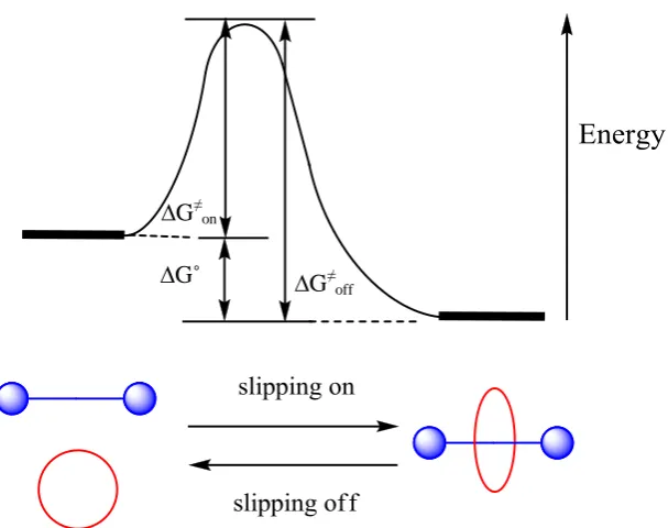
5
preformed stoppered axle and a macrocycle precursor is ‘clipped’ around it. In the slippingapproach the axle and macrocycle are preformed and heat is applied to distort the
macrocycle so that it can pass over one of the stoppers. Once cooled the macrocycle is
trapped on the thread.
The slippage approach requires the precise tuning of the macrocycle cavity and stopper size.
Enough thermal energy needs to be added to the system to allow the macrocycle to squeeze
it over the stoppers. On cooling the macrocycle can’t surmount the steric barrier of the
stopper.
1.5 Non-Metal Templates
The use and manipulation of intermolecular forces has provided an abundance of
mechanically interlocked molecules. There are many examples of metal ligand interactions
used to template the synthesis of rotaxanes and catenanes. This thesis focuses on the
assembly of rotaxanes using the interactions between crown ethers and ammonium or
pyridinium templates.
1.5.1 Hydrogen bonding
Hydrogen bonding is an important interaction found in nature and is used to assemble DNA
double helix and the secondary structure of peptides. Synthetic chemists have used hydrogen
bonding to construct rotaxanes and catenanes. One of the more widely used templates for
rotaxane formation is the secondary ammonium ion binding site which interacts with crown
ether type macrocycles primarily through hydrogen bonding. This binding template was first
investigated by both Busch31 and Stoddart.21,32 Busch has developed a thread with an anthracene moiety at one terminal end and a primary amine on the other. Incorporated in the
thread is a secondary ammonium ion available for binding with dibenzo-24-crown-8
(DB24C8). The macrocycle is trapped onto the axle in an acylating reaction to give rotaxane
6
bonding between the ammonium ion hydrogen’s and crown ether oxygen atoms thattemplate the interlocking of the two components.
Scheme 1.1 Interfacial synthesis of rotaxane 1.04, facilitated by hydrogen bonding in a ‘threading followed by
stoppering’ protocol.31
Stoddart32-33 incorporated both one and two ammonium binding sites into axles. In a ‘threading followed by stoppering’ protocol with DB24C8 the group successfully
synthesised both [2] and [3]rotaxanes using this binding motif
Figure 1.3
.Figure 1.3 [3]Rotaxane containing two secondary ammonium ion binding sites.
Hydrogen bonding is also a valuable interaction in the synthesis of amide containing
rotaxanes. Tetralactam macrocycles were originally developed by Hunter34 and Vögtle35 towards the synthesis of catenanes. Leigh36 discovered a catenane synthesis from two simple reagents and initially exploited this approach in a clipping strategy where the amide groups
are used to both construct the macrocycle and direct rotaxane formation with an amide
7
presence of an amide containing thread in the reaction solution acts as an auxiliary for themacrocycle to form around and provides an axle for rotaxane formation all mediated by
hydrogen bonding (Scheme 1.2).
Scheme 1.2 Leigh’s use of hydrogen bonding to synthesise [2]rotaxane 1.08.
Further development of the amide binding template towards the synthesis of higher order
rotaxanes has been realised by Vögtle. Synthesis of a [3]rotaxane composed of two
tetralactam macrocycles and a thread with two amide stations was successfully achieved
however yields of the [3]rotaxane were very low.38 More recently the group has created complex architectures utilising threads with amide binding site and sulfonamide wheels
where the wheels are capable of bridging to one another when more than one is present.39
1.5.2 π-π Interactions
The use of π-π interactions to form rotaxanes has been employed by a number of groups.
This relies on using a π electron deficient component and a complimentary π electron rich
component. A recent review by Stoddart has discussed the importance of this intermolecular
interaction in the formation of mechanically interlocked structures.40 Work carried out by Stoddart in the early 90’s has shown how utilisation of these interactions can form
rotaxanes.41 The cavity of the electron deficient cyclobis(paraquat-p-phenylene) (CBPQT4+) macrocycle 1.09 has been shown to bind with the electron rich 1,5-dimethoxynaphthalene
(DNP). There are both face to face and edge to face π-π interactions observed in the solid
8
CBPQT4+ macrocycle 1.09 has also been shown to bind with biphenyl42 and the π-electron donor tetrathiafulvalene (TTF) unit.43 Stoddart has successfully produced a number of rotaxanes using this macrocycle including [2]rotaxane 1.10 shown in Figure 1.4.44Figure 1.4 Stoddart [2]rotaxane 1.10 with a DNP binding site and CBPQT4+ macrocycle.
The Becher45 group have also used CBPQT4+ macrocycle to synthesise [2]rotaxanes with multiple TTF binding sites as shown in Figure 1.5. The CBPQT4+ macrocycle can ‘shuttle’ from one TTF site to the other. Threads with up to three stations were synthesised containing
TTF binding sites.
9
Other groups have exploited the use of π-π interactions in the formation of interlockedstructures. Loeb and co-workers46 developed the bispyridinium template which has been shown to have excellent binding via both π stacking and hydrogen bonding interactions with
crown ether type macrocycles. This binding motif has been successfully used to synthesise a
number of mechanically interlocked architectures. Loeb and co-workers have also used the
bispyridinium template to design more intricate supramolecular structures. Using
functionalised DB24C8 he was able to synthesise a variety of branched higher order
[n]rotaxanes (n = 2-4) and an example (1.13) is shown in Figure 1.6
.
47Figure 1.6 Loeb branched [n]rotaxane.
Other groups have utilised the bispyridinium template in order to synthesise a molecular
shuttle. Stoddart and co workers48 have synthesised an axle with two binding sites; a 1,2-bis -(pyridinium)ethane site and a secondary dialkylammonium site. DB24C8 is known to bind
both of these motifs and with the use of pH they were able to exert some control over the
position of the macrocycle on the axle shown in Scheme 1.3. The two sites have different
binding affinities with DB24C8 with the Ka of the secondary dibenzylammonium
hexafluorophosphate site at 420 M-1 and the 1,2-bis-(pyridinium)ethane
hexafluorophosphate site at 167 M-1. When both sites are charged, the DB24C8 resides predominantly over the ammonium binding site. The ammonium site can be deprotonated
10
Reprotonation of the ammonium site can be carried out with TFA causing the crown ether tosit predominantly back at the ammonium site as monitored by 1H NMR.
Scheme 1.3 A pH switchable rotaxane.48
1.5.3 Anion Template
Anion binding templates can also be used in order to synthesise mechanically interlocked
structures. Recent work by P. D. Beer49 has shown rotaxane formation via a chloride anion recognition template using a clipping method. This was performed by taking a stoppered
pyridinium chloride ion pair ‘thread’ with two porphyrin ring stoppers. Carrying out ring
closing metathesis (RCM) of the acyclic bis-vinyl-functionalised isophthalamide produced
the rotaxane 1.20 in a 30% yield. The chloride template in the interlocked system can be
exchanged for other ions. With this system the group has successfully developed a number
of [2]rotaxanes with porphryin incorporated into the thread and the macrocycle. The Beer
group have also used this anion template approach to synthesise a variety of [2] catenanes
50-51
and [2]rotaxanes.52-53 Further work using anion templates allowed groups to synthesise molecular shuttles54 and molecular machines.55 Developing supramolecular structures templated by anions is an interesting area as ions play an essential role in many biological
11
Scheme 1.4 Beer porphyrin stoppered [2]rotaxane 1.20 formed by anion templation. Reagents and conditions: i) 1-Ethyl-3-(3-dimethylaminopropyl)carbodiimide (EDAC), Hydroxybenzotriazole (HOBt), 4-Dimethylaminopyridine (DMAP), CH2Cl2, 0˚C, 10 min, RT, 48h, 59%; ii) MeI, dimethylformamide (DMF),70˚C, 40 mins; iii) NaCl, CH2Cl2/H2O, 95%; iv) Grubbs’ 2nd generation catalyst, CH2Cl2, RT, 24h, 30%; v)
12
1.5.4 Hydrophobic Interactions
Hydrophobic interactions comprise a further weak force that can be exploited in the
synthesis of rotaxanes. One of the most notable macrocyclic structures that takes advantage
of these interactions are cyclodextrins. They consist of a hydrophobic cavity and a
hydrophilic exterior. The first report of cyclodextrins used in the synthesis of rotaxanes
using hydrophobic effects as the driving force was by Ogino56. Taking either α or β cyclodextrin, the macrocycle was threaded over a 1,10 diaminododecane chain and end
capped with a bis(ethylenediamine)cobalt(III) complex to provide the bulky stopper groups
forming a [2]rotaxane.
Cyclodextrin containing rotaxanes have a wide variety of applications including their use as
long lasting dyes. This is a result of the dye functionalised axle being ‘protected’ by the
macrocycle surrounding it, blocking interactions with other molecules giving it an enhanced
stability. An example of rotaxanes used as dyes has been reported by Anderson et al. 57 Cyanine dyes have potential applications such as their use in photographic sensitizers, laser
dyes and biological fluorescence probes, but they suffer from a low photochemical stability.
To overcome this limitation, a rotaxane was developed in which the chromophore was
trapped inside a cyclodextrin cavity. These rotaxanes showed enhanced fluorescence and
photostability in several different solvents.
Further work by Anderson et al, also addressed some key questions to improve the
understanding of such complexes.58 This included studies on the binding of the dye and the chromophore lifetime when encapsulated within cyclodextrin. In this instance, a
chlorotriazine-functionalised azo dye was synthesised and used for the experiments. When
encapsulated, it was found that it had increased stability to bleaching but there was no
13
1.6 Methods of Formation
Template-directed synthetic methods to produce rotaxanes have been developed to enhance
yields of these mechanically interlocked structures. They use specific non-covalent
interactions between the components holding them in the appropriate orientation to produce
the rotaxane. Both covalent and non-covalent approaches have been used as the concluding
step in rotaxanes synthesis. As discussed earlier there are three general methods towards the
synthesis of rotaxanes. After reviewing some of the different interactions that are required to
form these structures, we now look into more detail at the synthetic protocols that provide us
with such mechanically interlocked architectures.
1.6.1 Template Directed Synthesis via the ‘Threading Followed by Stoppering’
Approach
One of the more successful and widely used approaches to the synthesis of rotaxanes, is
‘threading followed by stoppering’. It involves a kinetically controlled reaction, where the
axle and macrocycle are synthesised separately and the macrocycle is then threaded onto the
axle exploiting intermolecular forces to produce an intermediate pseudorotaxane. This is
then transformed into a rotaxane by the covalent attachment of bulky stopper groups, onto
the ends of the axle.59 We have seen an example of this previously by Stoddart and Fyfe33 involving the threading of DB24C8, onto an axle containing a secondary dialkylammonium
moiety. The crown is held in place as a result of the weak, non-covalent hydrogen bonds
with the axle. The pseudorotaxane is stoppered when the azido terminating ends are reacted
with acetylenedicarboxylate in a 1,3-dipolar cycloaddition to give rotaxane 1.05. Stoddart
has also used the Cu(I) catalysed 1,3-dipolar cycloaddition reaction ‘CuAAC click
chemistry’ in order to generate stoppers.60
[2]Pseudorotaxane 1.21 was formed from a thread
containing a DNP binding site and the CBPQT4+ macrocycle. Addition of a propargyl functionalised bulky stopper group 1.22 in the presence of ascorbic acid and CuSO4.5H2O in
14
Scheme 1.5 Synthesis of [2]rotaxane 1.23 via the ‘threading followed by stoppering’ protocol. a) DMF, CBPQT4+, -10˚C; b) CuSO4.5H2O, DMF, -10˚C, 82%.
There have been numerous reports of rotaxanes synthesised using the ‘threading followed by
stoppering’ approach, but there are still a restricted number of chemical reactions that can be
used to create the stopper. This is because many reaction conditions that could be used to
introduce stopper groups include the use of polar solvents, high temperatures, the presence
of a strong base or produce competitive hydrogen bonding counter ions. This makes them
unsuitable as these may lead to dissociation of the pseudorotaxane complex, producing low
yields of rotaxanes.61
Triphenylphosphine (PPh3) can also be utilised as the bulky stopper group in a ‘threading
followed by stoppering’ as shown by Stoddart.62
A dibenzyl ammonium binding motif
containing aryl p-bromomethyl groups incorporated can be threaded with DB24C8 in
15
carried out by the addition of PPh3 which attacks the bromomethyl groups of the interlockedaxle (Scheme 1.6
)
.Scheme 1.6 Stoddart synthesis of [2]rotaxane using triphosphonium ‘stoppers’ via the ‘threading followed by stoppering’ protocol. Reagents and conditions; a) CH2Cl2, CH3CN, DB24C8; b) PPh3, NH4PF6, H2O, 55%.
Stoddart has further exploited this method to synthesise dendrimers with rotaxane like
branches.63 In this case after the original ‘stoppering reaction’ with PPh3, a ‘stopper
exchange’ reaction was then performed utilising a bulky aldehyde in a Wittig reaction and
gave the new rotaxane in high yield.
Zheng and co-workers64 have also taken advantage of the ‘threading followed by stoppering’ protocol utilising an ammonium ion binding motif and the DB24C8 macrocycle. The
thiol-ene coupling reaction was used to attach bulky stopper groups to the terminating ends of the
axle trapping the macrocycle into place. A similar approach was first used by Takata65 in 1999, however, low yields were observed due to the high temperature requirement of the
reaction which was found to destabilise the delicate intermolecular forces between
16
pseudorotaxane in CH2Cl2 after irradiation with a UV lamp (λex = 365nm) at roomtemperature under inert conditions to give the [2]rotaxane in a 75% yield (Scheme 1.7).
Scheme 1.7 Synthesis of [2]rotaxane 1.29 via a thiol-ene stoppering reaction. Reagents and conditions: a) CH2Cl2, DB24C8, UV Irradiation (λex=365nm), RT, 1h, 75%.
Cycloaddition reactions have been shown to be useful in the synthesis of rotaxanes
especially when incorporating stoppers onto pseudorotaxanes in the ‘threading followed by
stoppering' protocol. We have seen Stoddart66 report the copper catalysed azide-alkyne reaction now commonly referred to as ‘click chemistry’ to stopper ammonium centred
rotaxanes. Bohmer67 has also used a cycloaddition reaction to create rotaxanes. He was able to heat a pseudorotaxane containing maleimide end groups with a functionalised anthracene
to trap the interlocked complex as its Diels-Alder product in toluene at 100˚C.
Takata68-69 et al have utilised the Diels-Alder reaction to incorporate C60 onto rotaxanes
producing a variety of C60 containing interlocked compounds. The fullerene could be added
17
undergo the Diels-Alder reaction so it can be introduced onto the pseudorotaxane accordingto the ‘threading followed by stoppering’ approach. The sulfolene can act as a masked diene
on the ammonium ion axle trapping the crown wheel by a Diels-Alder reaction with C60 at
80°C to afford the C60 rotaxane 1.31 in a 33% yield (Scheme 1.8). 68
Scheme 1.8 Synthesis of [2]rotaxane 1.31. Reagents and conditions: a) 1,2-Dichlorobenzene, C60, 80˚C, 33%.
1.6.2 Template-Directed Synthesis via the Clipping Approach
In 2001, Stoddart70 reported the template directed synthesis of a [2]rotaxane in a clipping approach under thermodynamic control. The kinetically stable [2]rotaxane was isolated and
characterised (Scheme 1.9). The procedure involved synthesising a macrocycle from two
components in a condensation reaction, while encompassing a templating NH2 +
group of a
dialkylammonium ion with bulky stoppers at each end of the axle. This provided a rotaxane
consisting of a dumbbell-shaped template surrounded by a macrocyclic diimine. These
imino bonds can also be reduced giving a robust diamine macrocycle.
From analysis, it was found that the [2]rotaxane was the thermodynamic product, but did
revert gradually back to its original components when removed from the reaction mixture.
18
a template directed approach using clipping, producing a [2]rotaxane under thermodynamiccontrol. Stoddart has used this approach to synthesise [n]rotaxanes where ‘n’ is up to 11.30
Scheme 1.9 Synthesis of [2]rotaxane 1.34via the ‘clipping’ approach.
1.6.3 Self-Assembly Approach via Slipping
A further protocol for the synthesis of [n]rotaxanes is a relatively simple self assembly
approach, known as ‘slipping’.71-72
The macrocycle cavity must be large enough to allow the
stoppered ends of an axle to pass through, once an appropriate amount of thermal energy has
been introduced to the system. Raymo and Stoddart,73 have described the synthesis of [n]rotaxanes (up to n = 4) using this method, as well as describing the kinetics of the
process. Upon heating together a stoppered axle with a macrocycle in solution, the
macrocycle can ‘slip’74
over the bulky terminal end group to produce the molecular
assembly. Once cooled, the macrocycle is trapped on the thread as it doesn’t have the
thermal energy to surmount the steric barrier provided by the stoppers (
Figure 1.7
). Therotaxane formed is both kinetically and thermodynamically stable at the lower temperature.
Lowering the stability of the rotaxane, for example by changing the polarity of the solvent,
can make the free components more favourable so now the addition of enough thermal
19
∆G≠off
∆G≠ on
[image:43.595.168.472.68.308.2]∆G˚
Figure 1.7 Schematic of the ‘slipping’ protocol.
1.6.4 Threading Followed by Swelling Approach
Chiu et al75 have described a novel method of stopper forming reactions in rotaxane
synthesis. The ‘threading followed by swelling’ approach involves swelling of the terminal
group on the axle of a pseudorotaxane complex, enlarging it sufficiently to prevent the
macrocycle from slipping off. This approach has some unique features including the
enlargement of the terminal group is attained without any additional atoms or functional
groups having to be added during rotaxane formation. The macrocycle must be able to pass
over the terminal end of the axle before, but not after swelling, and the swelling process
should be conducted under controllable conditions. Using a
cis-1-[(Z)-alk-1’-enyl]-2-vinylcyclopropane moiety for the swelling reaction, the thread (1.36) containing a
dibenzylammonium ion was threaded by a macrocycle 1.35. The [2]pseudorotaxane 1.37
was then converted to a [2]rotaxane 1.38 by heating the complex converting the
cis-1-[(Z)-alk-1’-enyl]-2-vinylcyclopropane moiety into a bulky cycloheptadiene group through a Cope
20
Scheme 1.10 Synthesis of [2]rotaxane 1.38via the ‘threading followed by swelling’ approach.1.7 Potential Uses and Scientific Interest
In recent years, there has been a significant development in supramolecular chemistry. The
emergence of molecular machinery and highly complex self-assembled structures are
becoming more apparent. As a result of such research, a number of advances have
materialised in the use of such structures in nanotechnology. Interlocked compounds such as
catenanes and rotaxanes are one such area of importance.76 Rotaxanes in particular are receiving much interest in new research as they have the ability to act as molecular machines
and switches,77 valves, insulated wires,78 drug delivery vehicles,79 wheels,80 scaffolds81 and in nanoelectronics.82 Exploiting the week intermolecular forces we have seen many examples of the synthesis of these structures come to light over the last three decades.
1.7.1 Valves
Stoddart78, has developed rotaxanes that are able to act as valves, trapping and releasing molecules under chemical and light control. These then have applications in sensors and
controlled drug release. Using pH stimulation and competitive binding in order to control
‘gatekeeper supermolecules’, the openings of nanosized pores on silica particles were able to
21
1.7.2 Wheels
Investigating configurational entropy of protein-ligand interactions to measure complex
stability, Smithrud80 used host-guest complexes, rather than the traditional lock-and-key or induced-fit model. Rotaxane axles act as the synthetic hosts, with bulky calixarenes and
cyclophanes used as ‘stoppers’. Attaching functional groups to the macrocycle (wheel)
allowed guest recognition. The host-guest association was measured in both water and
DMSO. The binding sites were arranged over several parts of the axle to create a
relationship between guest association and conformational changes that occur as the wheel
moves between each site. The hosts use several conformations to bind guests so are excellent
models of protein binding domains. From these studies, an increase in entropy of binding
has been observed on addition of the wheel to the host. Increasing motion of the wheel is
thought to be where this originates from, showing favourable configurational entropy which
aids complex formation.
1.7.3 Molecular Switches
The relative movement of the interlocked components of a rotaxane can be modulated in a
controlled manner in the development of molecular switches and shuttles. There is great
interest is such complexes with research into several methods of stimulation including
chemical, electrochemical and photochemical processes. Stoddart et al83 reported one of the first [2]rotaxanes to act as a ‘molecular shuttle’. They described the complex as a
tetracationic “bead” that shuttles between two identical “stations”. It consisted of a CBPQT4+
macrocycle acting as the “bead” on a polyether thread with hydroquinol units to act as the
“stations”. The ends of the rotaxane were stoppered by large triisopropylsilyl groups
preventing the macrocycle from slipping off. (Scheme 1.11) The shuttling motion was
22
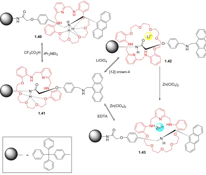
Scheme 1.11 Stoddart’s first example of a molecular shuttle.A molecular shuttle has recently been reported by Li and co-workers84 to drive a multilevel fluorescence switch. It is a [2]rotaxane prepared by a thermodynamically controlled,
template induced clipping method. The thread has two recognition sites which are separated
by a phenyl unit, these are -NH2 +
- and an amide. When protonated, the macrocycle binds to
the -NH2 +
- region through a variety of non-covalent interactions. When the ammonium ion is
deprotonated, the macrocycle prefers to hydrogen bond to the amide region. Addition of
either Li+ or Zn2+ ions to the system then controls the movement from one recognition site to the other. All three processes result in a fluorescent response (Figure 1.8) and it is pH
23
Figure 1.8 A pH switchable molecular switch.The Stoddart group have successfully synthesised a bistable [2]rotaxane which can be
controlled thermodynamically. The macrocyclic ring structure is the π electron deficient
CBPQT4+ ring and the axle contains two different π electron accepting moieties which are a TTF and DNP units. The CBPQT4+ macrocycle was threaded onto an axle with two terminating azide groups. The bulky stoppers were attached in a ‘CuAAC’ reaction to give
the bistable [2]rotaxane. The position of the macrocycle could be controlled via oxidation
24
Scheme 1.12 Schematic of a bistable [2]rotaxane.A more recent example of this molecular switch has been created by Stoddart.86 They have further developed the bistable [2]rotaxane with a CBPQT4+ π electron deficient macrocycle and the axle again containing the TTF and DNP units. Located in the central part of the axle
is a 3,5,3’,5’-tetramethylazobenzene (TMeAB) unit which is photoactive and can change
between its cis and trans conformations. In the axle’s neutral form the CBPQT4+ macrocycle resides over the more π electron rich TTF unit. Upon oxidation the CBPQT4+ is ‘switched’ to
the DNP moiety. The ‘switching’ process is also controlled by the photo induced
isomerisation of TMeAB unit. When in the trans configuration the CBPQT4+ macrocycle can move freely between stations. Once in the cis configuration the macrocycle now has a much
larger energy barrier to overcome due to steric hindrance which provides further control of
25
1.8 Transition Metal Strategy
Metal templating strategies have been a key area in synthesising interlocked architectures.
Using transition metals towards templating the synthesis of supramolecular molecules has
been advantageous. Early work by Sauvage and co-workers87 utilised a transition metal to orientate ligands in an exact position to facilitate the formation of a macrocycle by covalent
bond formation leading to the construction of a catenane.
There has been much work using copper (I) as the templating metal due to its preferred
tetrahedral co-ordination geometry. It holds the two components in an appropriate
orientation to allow further reactions to occur forming the desired interlocked structures. An
early example shown by Sauvage88 has taken two diphenol ligands around the metal ion Cu+ and reacting with 1,14-diiodo-3,6,9,12-tetraoxatetradecane to give a metallocatanene in a
27% yield (Scheme 1.13). A final demetallation with tetramethylammonium cyanide gives
the two interlocked macrocycles. The same method has also been successfully used towards
the synthesis of [n]rotaxanes89-90 and other catenane systems.91-92 Further development in this area has seen these interlocked structures synthesised in much higher yields.93 A variety of transition metals can be used in the formation of these supramolecular structures including
palladium94 and ruthenium.95
Scheme 1.13 Reagents and conditions: a) Cu(MeCN)4.BF4; b) DMF, 1,14-diiodo-3,6,9,12-tetraoxatetradecane,
26%.
Other groups have used the transition metal template strategy to synthesise molecular
26
metal acts as both the template and catalyst.96-97 For the reaction to proceed, it requires a catalytically active metal centre incorporated into a macrocycle that will allow covalent bondformation to occur in the cavity of the ring. A schematic representation of the reaction is
shown in Figure 1.9. In this case a stoichiometric quantity of the metal can be added to
‘stitch’ the components together. A covalent bond forming step takes place followed by
demetallation to give the interlocked structure. This reaction has also been achieved using
catalytic amounts of metal. A range of reactions are able to be exploited to synthesise
rotaxanes in the active template metal approach. These include the CuAAC click reaction,96 Cu mediated alkyne homocouplings (Glaser reaction)98-99 and palladium catalysed cross coupling reactions.100 There has also been success synthesising catenanes using the active metal template approach using the CuAAC reaction101 and Glaser homocoupling reaction.102
Figure 1.9 Schematic representation of the active metal template protocol. i) Metal addition; ii) Complexation and covalent bond formation; iii) Demetallation and [2]rotaxane formation.
More recently Goldup103 has also used the active template approach towards synthesising rotaxanes first pioneered by Leigh.96,104 Using the widely exploited CuAAC reaction and applying it to the active template approach the group have used the copper(I) catalysed
azide-alkyne click active template reaction (CuAAC-AT) to synthesise a variety of
molecular architectures in high yields. This method has been successful varying the chain
length and stopper size and the macrocycle cavity to produce supramolecular structures.
More complex architectures such as molecular shuttles105 can be synthesised using a metal template protocol. In 2007 Leigh has shown how ‘CuAAC click chemistry’ can be used to
27
used as the ligand with a Cu(MeCN)4PF6 metal catalyst and a diazide. The two cycloadditionreactions that occur provide a bistriazole thread with an encompassing macrocycle giving
[2]rotaxane 1.52 in a 74% yield. Demetallation is performed with KCN and the macrocycle
is free to move along the length of the thread. This was confirmed by 1H NMR where shielding was observed on several proton signals of the thread. Reintroducing Cu(I) to the
system provided fast shuttling between the two triazole stations (Scheme 1.14). However
addition of PdCl2 shows two distinct peaks for the triazole indicating the macrocycle is in a
fixed position on the thread and can no longer shuttle between the sites.
Scheme 1.14 Reagents and conditions: a) Cu(MeCN)4PF6 (1 equiv), CD2Cl2(90%)/CD3CN(10%), 25˚C, 5 min,
![Figure 1.4 Stoddart [2]rotaxane 1.10 with a DNP binding site and CBPQT4+ macrocycle.](https://thumb-us.123doks.com/thumbv2/123dok_us/9655180.467488/32.595.114.529.445.709/figure-stoddart-rotaxane-dnp-binding-site-cbpqt-macrocycle.webp)
![Figure 2.2 Unsymmetrical [2]rotaxane 2.01 and symmetrical [2]rotaxane 2.02.](https://thumb-us.123doks.com/thumbv2/123dok_us/9655180.467488/55.595.188.445.148.350/figure-unsymmetrical-rotaxane-and-symmetrical-rotaxane.webp)

![Figure 2.5 1H NMR (400 MHz, CD3CN, 300K) stacking plot of i) DB24C8; ii) [2]Rotaxane 2.13 and iii)](https://thumb-us.123doks.com/thumbv2/123dok_us/9655180.467488/63.595.112.525.71.347/figure-nmr-mhz-cd-cn-stacking-plot-rotaxane.webp)
![Figure 2.6 1H NMR (400 MHz, CD3CN, 300K) stacking plot of i) DB24C8; ii) [3]Rotaxane 2.26 and iii)](https://thumb-us.123doks.com/thumbv2/123dok_us/9655180.467488/67.595.113.524.66.348/figure-nmr-mhz-cd-cn-stacking-plot-rotaxane.webp)
![Figure 2.7 1H NMR spectra of a) [2]pseudorotaxane 2.46 in DMSO-d6, RT; b) [2]pseudorotaxane 2.46 in](https://thumb-us.123doks.com/thumbv2/123dok_us/9655180.467488/73.595.117.526.61.398/figure-h-nmr-spectra-pseudorotaxane-dmso-rt-pseudorotaxane.webp)
![Figure 2.11 Solid state structure side on view of [2]pseudorotaxane 2.53 showing hydrogen bonding between the](https://thumb-us.123doks.com/thumbv2/123dok_us/9655180.467488/79.595.145.523.137.393/figure-solid-state-structure-pseudorotaxane-showing-hydrogen-bonding.webp)
![Figure 2.12 Solid state structure of [2]pseudorotaxane 2.56 showing the interlocked nature of crown and thread](https://thumb-us.123doks.com/thumbv2/123dok_us/9655180.467488/81.595.116.497.76.305/figure-solid-structure-pseudorotaxane-showing-interlocked-nature-thread.webp)
