Abstract—this paper presents a methodology that permit; from the NURBS models of surfaces to finish on 3-axis CNC milling machines using ball end mill cutters; the determination of the optimum tool and the minimization of the machining times for each surface. In the proposed methodology, the accessibility problem is first analyzed and then the optimal tool is selected from a database of tools. Next, and depending on the machining method, we select automatically the optimum sweeping method and the associated machining direction for the isoparametric method, and the selection of the optimum machining angle for parallel plane method. Once the tool path is generated, the movements of the CNC machine are simulated virtually. This process allows an important reduction in machining time and therefore the machining costs.
Index Terms—Accessibility, Interference, Free Form Surface, Machining Time, Machine Simulation.
I. INTRODUCTION
Free form parts are designed by the junction of an important number of free form surfaces and are used in the design and manufacture of molds, dies …etc. These parts are machined on 3 or 5 axes milling machines. The complex geometry of these parts and the different parameters that must be considered such as surface definition, tool dimensions and geometry, machining strategy, interferences and collisions, …etc., make the tool path generation a difficult task. Different problems related to the machining of free form surfaces have been considered by different researchers [1-9].
The machining time for these surfaces is very important and must be taken into account in tool path generation to reduce machining costs. This time depends on many parameters such as tool dimensions, machining method, feed rate, shape of the surfaces…etc. In our work, we are interested in tool dimensions, machining method and machine simulation. Different machining methods are used for finishing free form
Manuscript received October 9, 2006.
Mohamed Bey : Centre de Développement des Technologies Avancées (CDTA), Division Robotique et Productique, Cité 20 Août 1956, BP N°17 Baba Hassen, Algiers, Algeria, e-mail : [email protected].
Hessen Bendifallah : Centre de Développement des Technologies Avancées (CDTA), Division Robotique et Productique, Cité 20 Août 1956, BP N°17 Baba Hassen, Algiers, Algeria, e-mail : [email protected].
Meriem mazouzi : Centre de Développement des Technologies Avancées (CDTA), Division Robotique et Productique, Cité 20 Août 1956, BP N°17 Baba Hassen, Algiers, Algeria, e-mail : [email protected]
surfaces: isoparametric, Z-Constant, parallel plane …etc. In this work, we have considered the isoparametric and the parallel plane methods. The isoparametric method is based only on u and v parameters of the surfaces. For this method, we have many sweeping methods with different machining directions, which give different machining times and the user must choose only one based on his experience. The parallel plane machining method permits the machining of multiple adjoining surfaces and guarantees the continuity of the machining. For this method, the programmer, based on his experience, must introduce the machining angle that has direct influence on the machining time.
In this paper, we present a systematic methodology that permit, from NURBS surfaces to finish on 3-axis CNC milling machines using ball end mill cutters, the selection of the optimal tool from a database of tools, the optimum machining angle, the optimum sweeping method and the associated machining direction that give the shortest machining time.
II. PROPOSED METHODOLOGY
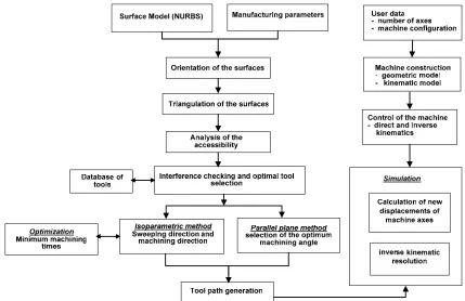
To improve machining efficiency by using the optimal tools and by the selection of the best sweeping method for 3-axis machining in order to reduce machining times and hence the machining costs, the proposed scheme for tool path generation is shown in Fig 1. In this scheme, the surfaces are oriented correctly in the first stage. In the second stage, the surfaces are approximated by a set of triangles, which are used in the next stages. In the third stage, the problem of accessibility is analyzed at each point of the surface to see if the surface can be machined on 3-axis machines or no. The decision is based on the calculated non-accessible surface areas. In the fourth stage, the problem of interferences is eliminated, for each surface, by the selection of the largest tool from a database of tools. The results from this stage are a set of tools that can machine the surfaces in the shortest machining time. In the fifth stage, we select the optimum machining direction and the optimum machining angle that reduces the machining times for each surface depending on the machining method. In the last stage, the CNC machine is constructed and the movements are simulated virtually.
The main advantage of this scheme is that it allows automatically the selection of the optimal ball end tools and the optimal sweeping method, and hence higher machining efficiency, without interaction with the user except in the introduction of the important manufacturing parameters.
An Integrated Application for Selection
of Optimum Strategies and Tools for
Finishing Free Form Surfaces
Fig 1. Scheme of the proposed tool path generation.
III. DEFINITION AND PROPERTIES OF NURBS SURFACES The shape of free form surfaces are described using parametric formulations such as Bezier, Rational Bezier, B-Spline and NURBS. However, the most powerful and used one is the NURBS. A NURBS surface is defined by:
• A network of (m+1)×(n+1) control points Pi,j with their
weight Wi,j (0 ≤ i ≤ m and 0 ≤ j ≤ n),
• Two knot vectors U and V in the u and v directions respectively,
• The degrees p and q in the u and v directions respectively. The NURBS surface is given by [10]:
∑∑
∑∑
= = = =
=
mi n
j
j i q j p i m
i n
j
j i j i q j p i
W
v
N
u
N
W
P
v
N
u
N
v
u
P
0 0
, ,
,
0 0
, , , ,
).
(
).
(
.
).
(
).
(
)
,
(
(1)Where
N
i,p( )
u
andN
j ,q( )
v
are the B-Spline basis functions of degree p and q respectively. In order to position correctly the tool relative to the surface, to determine the local shape of the surface at each point and the optimal tool radius, the unit normal vectorn
r
(
u
,
v
)
and the principal curvatures K1 and K2 are calculated using differential geometry.IV. SURFACE ORIENTATION CORRECTION
Free form parts are designed from an important number of surfaces obtained by Reverse Engineering or using CAD software. Therefore, these surfaces can have different orientations, which create problems at the time of the tool path
generation. Theses surfaces are machined on vertical 3 axes machines if for all points on the surface, the z component of the unit normal vector
n
r
(
u
,
v
)
is positive. To avoid this problem, the orientation of each surface is adjusted automatically by comparing the number of points with negative z component and the number of points with positive z component of the normal vector.V. TRIANGULATION OF SURFACES
To simplify the calculation of the intersection between a surface and a plane and to detect interferences, the surface is approximated by a set of simple geometric entities. Generally, the surface is approximated by a set of triangles. This step is called triangulation. In our work, this triangulation can be done in two different manners, uniform and adaptive triangulation. For the uniform triangulation, the number of triangles is fixed in the u direction and in the v direction for all surfaces. For the adaptive triangulation, the triangles are created and subdivided adaptively based on the triangulation parameters introduced by the user: the maximum length of each segment of the triangle, the maximum distance between each segment of the triangle and the surface and the maximum distance between the center of gravity of each triangle and the surface. For the two cases, the vertices of triangles are on the theoretical surfaces and for each vertex, the coordinates, the unit normal vector and the principal curvatures are calculated.
VI. PROBLEM OF ACCESSIBILITY
[image:2.612.94.523.54.332.2]machining. Collisions are inopportune contacts between the tool and parts surfaces or with other parts of the machine. In our work, we consider only tool and surfaces. The collision between the tool and the surfaces to machine arises when a certain regions of the surfaces are not accessible which is caused by the shape of the surfaces. It can happen when, in some regions of the surface, the angle α between the unit normal vector
n
r
to the surface and the tool axis (Z axis) exceeds 90° (invisible and non-accessible region), or when some regions of the surfaces are hidden by other regions (Fig 2). In our work, in order to detect the accessible and non-accessible regions, we use the set of the generated triangles without taking into account tool diameter. The surfaces can be divided in two types of regions. The first type is the regions where the z component of the unit normal vector to the surface is negative. For this type, the region is invisible and thus is inaccessible by the tool. The second type is the regions where the z component of the unit normal vector to the surface is positive. For this type, the region may be visible or invisible. If it is hidden by other regions of the surfaces then it is invisible else it is visible. The different regions are detected by the following algorithm:Input: Set of triangles and the area of all triangles; Output: accessible and not accessible regions; Begin
For each triangle: For each vertex:
If (nz < 0) vertex is invisible (non accessible);
If (nz > 0) then
For all triangles:
If the vertex is hidden by any triangle then vertex is invisible (non accessible);
Else vertex is visible (accessible);
If two vertices of a triangle are invisible then calculate the area of this triangle;
Calculate the percentage of the non-accessible area to the total area. End.
After the execution of the algorithm, if the percentage of the non-accessible area to the total area is equal to zero, then the surfaces can be machined on 3-axes machines. In the other case, the NC part programmer is warned that it is impossible to machine these surfaces on 3-axes machines but they can be machined on 4 or 5 axes machines. To calculate the accessible and the non-accessible area if we use a too of radius R, we first start by offsetting the surfaces by tool radius R and then we apply the above algorithm. In this case, the non-accessible area is greater than the one calculated without considering tool radius. In Fig 2, the blue region extends much farther out if we consider the radius of the tool.
Fig 2. Accessible and non accessible regions.
VII. INTERFERENCE AND OPTIMAL TOOL SELECTION For machining free form surfaces, the used tool must be constantly tangent to this surface (Fig 3). Generally, for 3-axes CNC machines, the ball end mill tool is used and its positions are given by [4]:
u r n r OC
OCL = C+ r− r
(2)
With: CC: cutter contact, CE: tool center, CL: cutter location,
u
r
the tool orientation vector and r the tool radius.Fig 3. Ball end mill position.
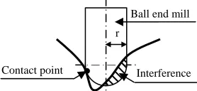
Another frequent problem is the existence of interferences, which are portions of the tool path at which the tool is not locally tangent to the surface and gouge the part surface (Fig 4). The sufficient condition of existence of the local interference at the contact point CC is the following: the
maximum principal curvature K2 at this point is greater than
1/R where R is the radius of the ball end mill [1]. Therefore, to manufacture a free form surface without interferences at all contact points, it is necessary to select tool radius that is less or equal than the smallest value of all principal radius of the surface. The interference at the contact point is eliminated, but may exist in the neighborhood. In order to select the optimum tool for each surface that eliminates interferences, we proceed in two steps. To select effectively the optimum tool radius, the generated triangles must give a very good approximation of the theoretical surface. If the triangulation is not good, the selected tool is not optimal and creates interferences. In the first step, for each surface, based on the two principal radiuses at all vertices of triangles, we choose the minimum positive value that eliminates the problem of interference at these points. If the surface is convex, we can theoretically select the largest tool. In the second step, from the database of tools we select a tool radius R that is less or equal to the radius calculated in the first step. After this, we position the tool at each vertex using the unit normal vector and we verify if there are vertices inside the sphere of radius R or no by checking the distance between tool center and the vertices in its neighborhood. If interference is found, another tool with smaller radius is selected and the second step is repeated until we find a tool without interferences. At the end, we obtain a tool for each surface.
Fig 4. Problem of the interference.
Surface
Non accessible region:
α>90° and nz<0
n
r
α
Point on the surface
Non accessible region:
α < 90° and nz>0
Z
r
Accessible region
Contact point Interference Ball end mill
[image:3.612.391.482.170.245.2] [image:3.612.64.283.620.718.2] [image:3.612.362.501.633.697.2]VIII. MACHINING OF FREE FORM SURFACES
Free form surfaces are machined by sweeping a tool according to a privileged direction and by specifying two machining parameters; the first defines the step forward distance or the deviation error and the second defines the step over distance or the scallop height. Different machining methods are used in the manufacture of these surfaces: isoparametric, Z-Constant, parallel plane…etc. The machining time for free form surfaces is very important and must be reduced. In our work, we have considered the isoparametric and the parallel plane methods.
A. Isoparametric Method
For this method, we have considered six sweeping strategies: One-Way, Zig-Zag, Concentric, In, Spiral-Out and Radial (Fig 5). The choice of a sweeping method depends on many parameters such as the shape of the surface and the machining time.
a. One-Way. b. Zig-Zag. c. Concentric.
d. Spiral-In. e. Spiral-Out. f. Radial. Fig 5. Different sweeping strategies.
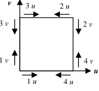
For each strategy, we have the possibility to choose a direction among eight possible directions (1u, 1v, 2u, 2v, 3u, 3v, 4u, 4v) (Fig 6). Generally, these machining directions do not give the same machining time. In our work, we have proposed two solutions. For the first one, the user selects a sweeping strategy for each surface, and then we select the machining direction that gives the shortest machining time. For the second one, the sweeping strategy and the associated machining direction are selected automatically for each surface.
Fig 6 Machining directions.
B. Parallel Plane Machining Method
In this method, the tool path is determined from the intersection points of a vertical plane, having any orientation, with the surfaces. In our work we have considered One-Way
and Zig-Zag sweeping strategies. To the sweeping strategy it is necessary to associate the deviation error and the distance between two consecutive planes for manufacturing the totality of surfaces. The generated triangles are used in the calculations of the points of intersection. For parallel machining method, the programmer, based on his experience, must introduce the machining angle α (the angle between XZ plane and the vertical plane) (Fig 7). This angle has a direct influence on the machining time and depends on many parameters. In order to minimize this time, the machining angle is selected automatically in two manners: for each surface or for all surfaces.
Fig 7. Machining angle.
IX. GEOMETRICAL MODELING OF CNC MILLING MACHINE The purpose of the total modeling of the machine is to precisely study the machining and the associated geometrical errors and to detect possible collisions between the different parts of the machine. The machine is modeled as a change of reference which makes possible to pass from a reference associated to the tool to a reference associated to the part. To do this, the homogeneous coordinates are used because they permit to apply the same transformations for points and vectors. Before the simulation of the movements of the various parts of the machine, we have passed by two stages. The first stage consists in building the various machine parts such as: the table, the spindle, the tool …etc, by using simple geometrical forms in 3D. The second stage consists in building the whole machine with the various possible configurations such as machines with 3 axes, 4 axes and 5 axes and the associated kinematics.
To construct the machine, we have used the object oriented method and the important objects used are the following:
1. Csurface_machines: is used for geometrical analysis and for the triangulation of the surfaces.
2. VMachine: this class with its sub-classes Vmachine3axis, Vmachine4axis and Vmachine5axis permit the construction and the visualization of the considered machine.
3. Cprimitives: this class with its sub-classes Csphere, Cbox, Cdisk, Ccylinder, Cface permit the construction of the different parts of the machine with their proper parameters.
4. Ccinematique: this class is used for resolving the problem of direct kinematics and inverse kinematics. 5. SimulateMachining: this class simulates virtually the
movements of the different parts of the machine. u
v
1 v
1 u
3 v
3 u 2 u
2 v
4 v
4 u
X Y
α : Machining angle
[image:4.612.339.539.199.303.2] [image:4.612.69.274.263.421.2] [image:4.612.118.219.567.660.2]X. RESULTS AND DISCUSSIONS
The proposed scheme for tool path optimization have been implemented in an object-oriented software running under Windows using C++ Builder and the graphics library OpenGL [11] and tested with different examples of free form surfaces. This software is designed for any NURBS free from surfaces to be machined on 3-axis CNC milling machines using ball end mill cutters. In the developed software, the user selects only the surfaces to be machined, chooses the machining method for each surface, selects the triangulation method and then introduces only the machining parameters, which are the scallop height and the deviation error for the isoparametric method and the distance between two planes and the sweeping method for the parallel plane method. Tool dimensions, feed rate and cutting speed are fixed once in the database of tools. After this, the software analyzes all surfaces and selects the optimum tool for each surface, and then automatically determines the sweeping method that reduces the machining time for each surface. Once the tool path is generated, the developed software simulates virtually the movements after building the machine. For making a decision, the software takes a time that depends on the number of the considered surfaces, complexity and dimensions of surfaces, machining parameters and the CPU of the computer.
A. Accessibility Checking
To check if a surface can be machined on 3 axes or no we have considered the surfaces in Fig 8.a. After application of the suggested method, the different regions are located and shown in Fig 8.b. The blue region can be machined on a 3 axis machine but the red and yellow regions cannot be machined on a 3 axis machine and require machines with 4 or 5 axes. The red zone has an angle between the normal and the tool axis greater than 90 and thus non accessible. The yellow zone is hidden and consequently it is non accessible.
a. Surface. b. Different regions. Fig 8. Accessibility checking of a free-form surface.
B. Machine Construction and Movements Simulation
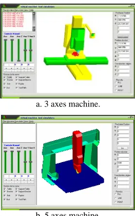
To simulate the movements of the various elements of the machine, we must firstly generate the tool path. Once the various positions of the tool are known, for each position the inverse kinematics is used to determine the new positions of the machine axes. The Fig 9.a shows the Graphical User Interface during the simulation of the movements of a milling machine with the tool path. The developed application permits to build and to simulate the movements of milling machines with 3, 4 and 5 axes. The Fig 9.a shows 3 axes machine and the Fig 9.b shows 5 axes machine.
a. 3 axes machine.
b. 5 axes machine.
Fig 9. Graphical user interface of the simulator.
C. Milling NURBS Surface using Parallel Plane Method
To demonstrate the automatic selection of the machining angle, we have considered the surface (Fig 10) defined by 7×7 control points and considering the sweeping methods One-Way and Zig-Zag. The considered machining parameters are: tool radius = 5 mm, feed rate = 50 mm/min, distance between two planes = 0.5 mm. For this surface there is no problem of accessibility. The intermediate obtained simulated machining times for this surface are given in Table I.
[image:5.612.369.508.47.269.2]The obtained results show the influence of the machining angle on machining times. For considered surface, the longest machining time is for an angle equal to 75°, the shortest machining time is for an angle equal to 0°, and the difference is nearly 2 hours. If the distance between two planes is reduced the difference becomes very important. This example shows the importance of the machining angle for reducing times and consequently costs.
Table. I. Machining times for the considered surface. Machining angle One-Way Zig-Zag
0° 19h27’13’’ 18h29’39’’
15° 19h55’47’’ 18h47’40’’
30° 20h35’12’’ 19h18’53’’
45° 21h11’03’’ 19h52’02’’
60° 21h33’41’’ 20h17’52’’
75° 21h35’30’’ 20h28’24’’
90° 21h20’37’’ 20h23’06’’
Difference 02h08’16’’ 01h58’44’’
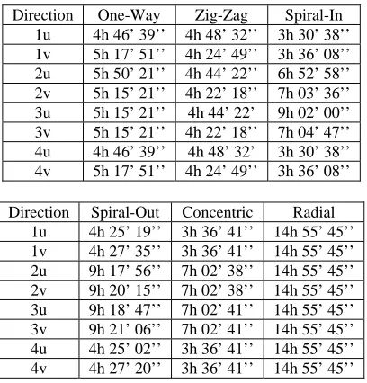
[image:5.612.50.296.458.588.2] [image:5.612.324.553.509.728.2]D. Milling NURBS Surface using Isoparametric Method In order to demonstrate the automatic selection of the machining direction, we have considered the surface (Fig 11) defined by 4×7 control points and considering the machining strategies One-Way, Zig-Zag, Spiral-In, Spiral-Out, Radial and Concentric with the following parameters: deviation error = 0.1mm, scallop height = 0.1mm, tool radius = 5mm, feed rate = 50mm/mn. There is no problem of accessibility for this surface. The intermediate obtained simulated machining times for this surface are given in Table II.
Fig 11. The considered free form surface.
[image:6.612.83.262.176.323.2]For this surface, we find differences even for the same machining strategy (Spiral-In, Spiral-Out and Concentric) and the difference between the minimum and maximum machining times is nearly 11 hours, which is very important. For a given manufacturing parameters, the machining time depends on the shape, properties and dimensions of the surface and on tool dimensions. In addition, it is not evident that all machining strategies produce surfaces that are in the interval of tolerance, so we must use machining simulation to choose the best strategy.
Table. II. Machining times for the considered surface.
Direction One-Way Zig-Zag Spiral-In 1u 4h 46’ 39’’ 4h 48’ 32’’ 3h 30’ 38’’ 1v 5h 17’ 51’’ 4h 24’ 49’’ 3h 36’ 08’’ 2u 5h 50’ 21’’ 4h 44’ 22’’ 6h 52’ 58’’ 2v 5h 15’ 21’’ 4h 22’ 18’’ 7h 03’ 36’’ 3u 5h 15’ 21’’ 4h 44’ 22’ 9h 02’ 00’’ 3v 5h 15’ 21’’ 4h 22’ 18’’ 7h 04’ 47’’ 4u 4h 46’ 39’’ 4h 48’ 32’ 3h 30’ 38’’ 4v 5h 17’ 51’’ 4h 24’ 49’’ 3h 36’ 08’’
Direction Spiral-Out Concentric Radial 1u 4h 25’ 19’’ 3h 36’ 41’’ 14h 55’ 45’’ 1v 4h 27’ 35’’ 3h 36’ 41’’ 14h 55’ 45’’ 2u 9h 17’ 56’’ 7h 02’ 38’’ 14h 55’ 45’’ 2v 9h 20’ 15’’ 7h 02’ 38’’ 14h 55’ 45’’ 3u 9h 18’ 47’’ 7h 02’ 41’’ 14h 55’ 45’’ 3v 9h 21’ 06’’ 7h 02’ 41’’ 14h 55’ 45’’ 4u 4h 25’ 02’’ 3h 36’ 41’’ 14h 55’ 45’’ 4v 4h 27’ 20’’ 3h 36’ 41’’ 14h 55’ 45’’
XI. CONCLUSION
In this paper, we have presented a systematic methodology that permit; from the NURBS surfaces to finish on 3-axis CNC milling machines using ball end mill cutters; the minimization of the machining times by the automatic selection of the optimal tools and optimum sweeping directions for the isoparametric and parallel plane methods and the construction and the simulation of movements of the milling machine. The proposed method permits an important reduction of machining costs, which is searched by manufacturers. In perspective of this work, we must integrate machining simulation in order to choose the best strategy. To make decisions in less time, it is very important to develop a distributed application because many calculations can be done on separate computers or on a computer with several processors.
REFERENCES
[1] Choi, B. K., Jun, C. S., Ball-end cutter interference avoidance in NC machining of sculptured surfaces, Computer Aided Design, Volume 21, 1989, pp 371-378.
[2] Choi, B. K., Lee, Hwang, C. S., J. S. and Jun, C. S., Compound surface modelling and machining, Computer Aided Design, Volume 20, 1988, pp 127-136.
[3] Jerard, R.B., Hussaini, S.Z., Drysdale, R.L. and B. Schaudt, Approximate Methods for Simulation and Verification of Numerically Controlled Machining Programs, The Visual Computer, vol. 5, no. 6, 1989.
[4] DUC, E., Usinage de formes gauches; contribution à l’amélioration de la qualité des trajectoires d’usinage, Thèse de doctorat à l'Ecole Normale Supérieure de Cachan, France 1998.
[5] Elber, G., Freeform surface region optimization for three and five axis milling, Computer Aided Design, Volume 27, 1995, pp 465-470. [6] Park, S. C., Tool path generation for Z-constant contour machining,
Computer Aided Design, Volume 35, 2003, pp 27-36.
[7] Tournier, C., Usinage de formes gauches; génération de trajets outil sans collision. Mémoire de DEA à l'Ecole Normale Supérieure de Cachan, France 1996.
[8] Yang, D. C. H., Han, Z., Interference detection and optimal tool selection in 3-axis NC machining of free-form surfaces, Computer Aided Design, volume 31, 1999, pp 303-315.
[9] Li, S. X. and Jerard, R. B., Non-isoparametric Three Axis Tool Path Generation for Finish Machining of Sculptured Surfaces, Geometric Modeling for Product Realization, ed. P.R. Wilson, M.J. Wozny, and M.J. Pratt, IFIP WG5.2, North Holland, pp 251-265, 1993.
[10] Farin, G., Courbes et surfaces pour la CGAO. Edition Masson, France 1992.
[image:6.612.72.276.488.701.2]