Abstract— After all preventive and mitigative measures considered in the design of a nuclear reactor, the installation still represents a residual risk to the outside world. Probabilistic Safety Assessment is a powerful method to survey the safety of nuclear reactors. In this study the occurrence frequency of different types of core damage states (CDS) which may potentially arise in TRR is evaluated by use of the recently developed Risk Assessment Tool (RAT) software which has been designed and represented in the Safety Research Center of Shiraz University. RAT uses Event Trees and Fault Trees to evaluate the total final core damage frequency through studying the frequencies of initiation events, and following their consequences has resulted in one type of the CDS.
The criterion must be of the order of smaller than 10-4 through IAEA standards for research reactors. Results show that the total final CDF for TRR is of the order of 10-6, which meets the criterion of nuclear research reactor.
Index Terms— TRIGA Research Reactor, Core Damage Frequency, Risk Assessment Tool, PSA, Beta Factor Model.
I. INTRODUCTION
An initiating event is an event that creates a disturbance in the plant and has the potential to lead to core damage, depending on the successful operation of the various mitigating systems in the plant. For the purpose of this analysis, the list of initiating events (IEs) was determined through Engineering Evaluation, Operational Experience and reference to previous lists of similar reactors.
Once accident IEs have been identified and grouped, it is necessary to determine the response of the plant to each group of initiating events.
Event trees are graphic models that order and reflect events according to the requirements for mitigation of each group of initiating events. Events or ‘headings’ of an event tree can be a safety function’s status, a system’s status, basic events occurring or operator actions.
Fault tree analysis is the most common method used for representing the failure logic of plant systems. The fault tree itself is a graphic model of the various parallel and sequential combinations of faults that will result in the occurrence of the predefined undesired event.
In general, dependent failures are defined as events in
Manuscript received September 9, 2009.
Mohammadreza Nematollahi was with safety Center of Shiraz University, 71348-51154, Shiraz, Iran. He is no with department of Mechanical engineering, Shiraz University. Tel./fax:+987116473474 E-mail address:
Shahabedin Kamyab is with the School of Engineering, Shiraz University 71348-51154, Shiraz, Iran .
which the probability of each failure is dependent on the occurrence of other failures. In this case, the probabilities of dependent events are usually, but not always, greater than the corresponding independent probabilities.
The major causes of dependence among a set of systems or components can be explicitly described and modelled by system reliability analysis models such as fault trees. However, other causes can be collectively modelled using the concept of common cause failures (CCF). CCFs are considered the collection of all sources of dependencies (Intersystem, Intercomponent and External Dependencies), especially between components that are not known or are difficult to explicitly model in the system or component reliability analysis. CCFs have been shown by many reliability studies to contribute significantly to the overall unavailability or unreliability of complex systems.
Beta factor Model is one of the single parameter models that use just one parameter in addition to the total component failure probability to calculate the CCF probabilities. The sole parameter of the model (β) can be associated with the fraction of the component failure rate that is due to common cause events shared by the other components in the system. That is,
Where: Β = λC / [λC + λI] = λC / λt λC = failure rate due to common cause failures λI = failure rate due to independent failure λt = λC + λI
Having the β value, we can use the expression of the multiple component failure frequency to calculate the required probabilities.
An important assumption of this model is that if a CCF shock strikes a redundant system, all components are assumed to fail immediately without any delays.
After calculating the common cause failure probabilities for redundant systems, they are added to fault trees logic to contribute to the overall probability.
II. METHODOLOGY OF EVALUATION OF CDF IN
TEHRAN RESEARCH REACTOR:
- Familiarization with the Plant and Information Gathering:
The 5 megawatt pool-type research reactor is a light-water moderated, heterogeneous, solid fuel reactor in which the water is also used for cooling and shielding. The reactor core is immersed in either section of a two-section concrete pool filled with water. One of the sections of the pool contains an experimental stall into which beam tubes and other experimental facilities converge. The other section is an open
Evaluating the Core Damage Frequency of a
TRIGA Research Reactor Using Risk
Assessment Tool Software
pool area for bulk irradiation studies. The pool is spanned by a manually operated bridge from which an aluminum tower that supports the reactor core is suspended. Control of the reactor is accomplished by the insertion or removal of neutron absorbing-control rods which are suspended from control-drives mounted on the Reactor Bridge. Additional control is provided by the inherent negative temperature coefficient of reactivity of the system.
The core has been fuelled with Low Enriched Uranium (LEU) elements of U3O8-Al type. The fuel enrichment is approximately 20% in weight of U-235. The equilibrium LEU core contains 23 standard fuel elements and 5 control fuel elements. Each standard fuel element consists of 19 flat plates inserted in two grooved side plates (lateral walls). The control fuel element is of the same size as the standard fuel element but consists of only 14 fuel plates to accommodate the fork type control rods.
Initiation Events Identification: Only internal IEs, i.e. hardware failures in the plant or faulty operations of plant hardware through human error or computer software deficiencies have been considered. Two major categories of IEs can be distinguished.
Loss of Coolant Accident initiator (LOCA) is an event that directly causes loss of integrity of the primary coolant pressure boundary. Transient initiators are those that could create the need for a reactor power reduction or shutdown and subsequent removal of decay heat.
Based on the response of the safety systems we have considered 11 groups of initiating events, of which four are LOCA initiators and the others are Transient initiators. Transient initiators are also subdivided to the following categories:
Loss of Offsite Power Supply (LOPS)
Loss of Flow, Forced Circulation Unavailable (LFFCU) Loss of Flow, Forced Circulation Available (LFFCA) Excess Reactivity Insertion (ERI)
As mentioned earlier, the next step after identification of IEs is to construct an Event tree which traces the following consequences (to final state which may be a CDS) associated with the performance of safety function systems.
Core Damage States: Core damage has been
conservatively assumed to occur when the available thermo-hydraulic models cannot support successful cool-down of the reactor core, given a particular state for the various safety systems. More detailed calculations might indicate that in some cases core damage is not actually occurring. All accident sequences identified do not lead to the same degree of core damage. Depending on the initiating event, the safety systems that operate and on the indications of the thermo-hydraulic analysis, eight states have been defined, of which two are just abnormal states (do not lead to core damage) and the others are core damage states. These eight states are described below:
- CDS1: When the reactor shutdown takes place
- CDS4: When the reactor does not shutdown in the case of reactivity accident, although the primary heat removal system works normally.
- CDS5: When the reactor does not shutdown in the case of a reactivity accident and the primary heat removal system also fails.
- CDS6: When the reactor shutdown takes place but the core is bared because of failure of the pool isolation system in the case of LOCA.
- CDS7: When the reactor shutdown does not take place but the core is bared because of failure of the pool isolation system in the case of LOCA.
- CDS8: When the reactor shutdown does not take place and both NC and FC systems work normally but because of opening of the safety flapper the core is bypassed.
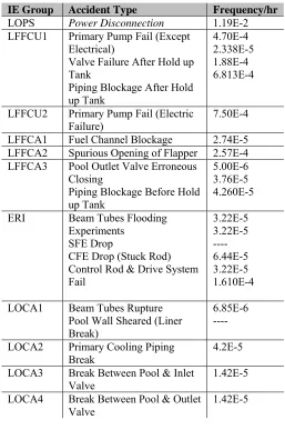
The data required for quantification of the models that yield the frequency of initiating events are the numbers of occurrences of the events and the total periods over which these events have been observed.
After definition and selection of initiating events, the frequency of occurrence of these events must be quantified. We consider that the frequency of initiating events is constant, i.e. that the events occur randomly in time, and that the distribution of times between occurrences is exponential. The parameter to be estimated therefore is the intensity λ of this process. Specific accident sequences are defined that consist of an initiating event group, specific system failures and successes and possible human responses. The system failures are in turn modelled in terms of basic event component unavailability and human error to identify their basic causes and to allow for the quantification of the system failure probabilities (unavailability) and accident sequence frequencies. Table 1 represents the probability results for an example data set of basic events which has been used in IEs frequency evaluation.
Dependent failures are considered by the use of β model. It should be noted that although β model can be used with some degree of accuracy for two component redundancy, the results tend to be conservative for a higher level of redundancy. Since in this research reactor the highest level of redundancy is two out of three components, and considering lack of data for dependent events, this model is the best selection to generate common cause failure probabilities.
To evaluate the final probability of each branch of an Event Tree which results in a specific probability of radioactive release, each stage must be quantified. This means that the probability of each stage must be calculated as the top event of associated fault tree by the aid of a logical combination of basic events through logic gates.
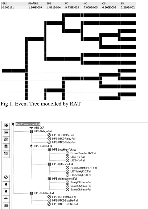
Ev ha m Th co tre Ta A of ca re le le co th pr de th da th Th sh It sy 2 ev ge Th fr It am th fla Si el fr ro so to sc pr A th re U el th th A no th co valuating the as been done modelled fault t he output of orresponding ees, the freque able 2. As mentioned e
f β-factor mod an be used wit edundancy; th evel of redunda evel of redund onsidering lac he best selec
robabilities. I ependent failu hat contain the
ata available w he β.
he β is consid hows the frequ should be no ystem scram ro scram rods to vent 'failure o eneric databas he final core d equencies are
is seen that th mong others. T he 'fuel chann
apper acciden ince the fai lectromagnets equency of to ods is very imp olution can be o find the opti cram condition
rohibit the scr Another major
he deficiency o elated CDS3 a Using online lements or ins he fuel channe his state of cor After all, it sho ot tend to sign he frequencie
onsidered in to
IV. FI
frequency of e through ap tree is represe f a fault tree IE occurrenc ency of 11 typ earlier, CCF pr del. However, th some degree
e results tend ancy. Since in dancy is two ck of data for ction to gen In some case ures data, it is p e generic valu we use the sim dered 0.15 thr uency of diffe oted that the ods is just calc o drop', becau of 5 scram rod
ses.
damage states reported in T he CDS3 and C
The accident nel blockage' nt'.
ilure of scr are the m otal core dama portant to decr
to test the ele imum electric n there is no r am rods from contributor to of detecting a also has the h video camer struments to d el is very help re damage. ould be notice nificant damag s of the six otal core dama
IGURESAND
f occurrence o ppropriate fau ented in Figur e is the failu ce. After deve pes of initiation robability is ev , generally sp e of accuracy d to be conserv
n this research o out of three dependent ev nerate comm es where the possible to use ues of β. Whe mple point esti
rough experts’ rent sorts of C CCF probabi culated for the use the failure ds to drop' is s (CDS) and th Table 4.
CDS8 have the initiators of th
and 'spuriou ram rods an most importan
age, altering t rease this cont ectromagnet sy cal current tha residual electr m dropping.
o core damag a foreign obje highest freque ra imaging, detect the pre pful to decreas ed that since t
ges, which are x core damag age frequency
DTABLES
of initiation e ult trees. A e 3 as an exam ure probabilit
eloping such n events is giv valuated by th peaking, this m
for two compo vative for a h
reactor the hi e components vents, this mod mon cause fa ere is not en e generic data en there is en
mators to calc ’ opinions. Ta CCFs in TRR. ility of shut d e event of 'failu e probability o extracted from heir correspon e highest frequ hese two state us opening o
nd correspon nt contributor
the shape of s tribution. The ystem of these at, in the case romagnetic fie ge of this reac ect in the core ncy amongot
instrumental ssure differen se the frequen two of the CD e CDS1 and C ge states are y. events RAT mple. ty of fault ven in he use model onent higher ighest s and del is ailure nough abases nough culate able 3 down ure of of the m the nding uency es are of the nding rs to scram other e rods e of a eld to ctor is e. The thers. fuel nce in ncy of DS do CDS6, e just Fig 1 Fig 2 Tabl
. Event Tree m
2. Fault Tree mo
le I. Basic Eve
modelled by RAT
odelled by RAT
ent Failure Pro
T
T
[image:3.595.304.544.47.385.2] [image:3.595.305.525.445.706.2]Table II. Initiating events Frequency
Table III. CCFs Probability
CCF Component Beta Probability
Emergency Ventilation
System(FANS) 0.15 4.542E-3
High Power Scram System-
BISTABLES 0.15 5.516E-7
High Power Scram System-
DETECTORS 0.15 9.919E-11
High Power Scram System-
HIGH VOLTAGE 0.15 1.587E-9
High Power Scram System- Ch.
INSTRUMENT 0.15 5.990E-6
High Power Scram System-
RELAYS 0.15 7.613E-6
High Radiation Scram System-
DETECTORS 0.15 9.00E-6
High Radiation Scram System-
RELAYS 0.15 2.00E-4
High Radiation Scram System-
BISTABLES 0.15 5.59E-5
[image:4.595.40.297.74.461.2]Shutdown System Scram Rods 0.15 1.525E-4
Table IV. CDS Frequencies (Descending Order)
Core Damage States Frequency Per
Operation Year
CDS3 6.797E-6 CDS8 1.438E-6 CDS4 1.047E-7 CDS2 2.758E-8 CDS5 1.038E-9 CDS7 1.706E-10 Total 8.638E-6
V. CONCLUSION
Results which have been obtained for CCFs show that dependent failure has a significant effect on CDF. Therefore, in some cases neglecting them would cause misleading results that may be absolutely smaller than the real results.
This level 1 PSA performed for TRR indicates, based on conservative assumptions that the total frequency of accidents that would lead to core damage from internal initiating events, is 8.368E-6 per year of reactor operation.
It is possible to make the CDF less than the current quantity after making some changes which must be designed in the plant composition and safety systems to improve their functions in the procedure of accident mitigation, as mentioned in the result and discussion section; as an example, the shape of the control rods and the mechanism of electromagnets.
Furthermore, the accident procedures of LOCA initiators must be well practiced by the operators to decrease the human error corresponding to these accidents which in turn will decrease the CDF.
The probabilistic safety criteria of IAEA for power reactors level 1 result is assigned a frequency of one core damage event in 10,000 years of plant operation for existing plants (10-4 per reactor operating year). Therefore, after everything mentioned above the core damage frequency of the Tehran Research Reactor (8.368E-6) is approximately 12 times lower than the acceptance criteria of IAEA for existing plants.
This frequency is not expected to significantly change, even when external events such as earthquake and fire risk are added because of the low frequency of occurrence of these events. It seems that this result meets the IAEA criterion.
VI. ABBREVIATIONSANDACRONYMS CDF : Core Damage Frequency
CDS : Core Damage State ERI : Excess Reactivity Insertion FC : Forced Circulation
LFFCA : Loss of Flow Force Recirculation Available LFFCU : Loss of Flow Force Recirculation Unavailable LOCA : Loss of Coolant Accident
LOPS : Loss of Offsite Power Supply
IE Group Accident Type Frequency/hr
LOPS Power Disconnection 1.19E-2
LFFCU1 Primary Pump Fail (Except Electrical)
Valve Failure After Hold up Tank
Piping Blockage After Hold up Tank
4.70E-4 2.338E-5 1.88E-4 6.813E-4
LFFCU2 Primary Pump Fail (Electric
Failure) 7.50E-4
LFFCA1 Fuel Channel Blockage 2.74E-5 LFFCA2 Spurious Opening of Flapper 2.57E-4 LFFCA3 Pool Outlet Valve Erroneous
Closing
Piping Blockage Before Hold up Tank
5.00E-6 3.76E-5 4.260E-5 ERI Beam Tubes Flooding
Experiments SFE Drop
CFE Drop (Stuck Rod) Control Rod & Drive System Fail
3.22E-5 3.22E-5 ---- 6.44E-5 3.22E-5 1.610E-4 LOCA1 Beam Tubes Rupture
Pool Wall Sheared (Liner Break)
6.85E-6 ---- LOCA2 Primary Cooling Piping
Break 4.2E-5
LOCA3 Break Between Pool & Inlet
Valve 1.42E-5
LOCA4 Break Between Pool & Outlet
REFERENCES
[1] IAEA-TECDOC-400, Probabilistic Safety Assessment for
Research Reactors, International Atomic Energy Agency, Vienna, 1986
[2] M. Modarres, What Every Engineer Should Know about
Reliability and Risk Analysis, Marcel Decker, New York, 1993
[3] M. Modarres, Risk Analysis In Engineering, Taylor & Francis,
2006
[4] A. Majdara, Design and Implementation of a Risk Monitor and its
Application for a Typical Research Reactor, M.Sc.Thesis in Nuclear Engineering, 2006
[5] A. Majdara and M.R. Nematollahi, Development and Application
of Risk Assessment, Reliability Engineering & Systems Safety, 93, 1130-1137, 2008
[6] NUREG-0492, Fault Tree Handbook, U.S. Nuclear Regulatory
Commission, Washington DC, USA, 1981
[7] M.Hosseini, Probabilistic Safety Assessment Of Tehran Research