A Formal Model Of SystemC Components Using
Fractal Hypergraphs
Nicolas Vall´ee
Bruno Monsuez
∗Abstract— In this paper, we introduce a new math-ematical structure: fractal hypergraph. Due to the hi-erarchical and compositional nature of fractal hyper-graphs, representations based on fractal hypergraphs can capture and abstract the object-oriented nature of SystemC. We propose a formal semantics of Sys-temC components based on fractal hypergraphs that has already be used in a formal debugger of SystemC components.
Keywords: SystemC, Formal semantics, Hierarchical Models, Hypergraphs
1 Introduction
SystemC becomes a popular language for modeling com-plex hardware systems. Compared with other hardware description languages, SystemC is more feasible for de-signing large-scaled systems and modeling high level be-haviors.
While a major goal of SystemC is to enable system ver-ification at an higher level of abstraction, formal verifi-cation of SystemC design is still in its infancy. The diffi-culty to statically analyze and verify SystemC comes from the object-oriented nature of SystemC that supports hi-erarchy, modularity and parametricy as well as from its sophisticated event driven simulation semantics.
If we focus on the object-oriented nature of SystemC, we can identify the following key aspects of SystemC that should be captured and fully supported by the formal rep-resentation of SystemC components in a formal verifica-tion tools to provide a valuable verdict.
∙ The formal representation copes with different ab-straction levels; it also must support the refinement.
∙ The formal representation must support program code as well as hardware description; a semantics for program execution and a semantics for system simu-lation must be provided.
∙ The formal representation must support assembling modular and parametrized components.
In this paper, we propose a new hierarchical model based on hypergraphs that can represent SystemC components and that provide the adequate constructions to capture
∗´Ecole Nationale Sup´erieure de Techniques Avanc´ees, UEI, 32 Bd
Victor, 75739 Paris cedex 15, France, [email protected]
the object-oriented nature of SystemC components. We also define a trace-based semantics based on hypergraphs and show how this hypergraph based semantics is ade-quate to represent SystemC components. We finally show how object-oriented and component-oriented operations like connecting a sub-component to a main component, instanciating a component with respect to type or value parameters can easily be expressed with this semantics. The paper is organized as follow; section 2 gives the math-ematical definition of the hypergraphs model: fractal hy-pergraphs and introduces the underlying trace based se-mantics; section 3 gives the semantics of SystemC com-ponents and finally section 4 presents how fundamental concepts like the compositional approach are nicely cap-tured by thisfractal hypergraphs based semantics.
2 A Fractal hypergraph based semantics
Graphs are certainly one of the simplest and most univer-sal model for a large variety of systems including hardware models as well as programs. If graphs define the structure of the model, graph transformation can be exploited to explain how the model is built (compilation or synthesis of the system) and how the model evolves (computation) of the system.However, when we want to represent complex circuits or systems as well as complex object-oriented system descrip-tion, the absence of hierarchy [1] is certainly one of the main default of graph-based representations. To overcome the limitation of graphs, we introduce a new mathematical extension of graphs calledfractal hypergraphs.
2.1 Fractal Hypergraphs
Hypergraphs [2] are a mathematical extension of graphs: A hypergraph is a graph whose hyperedges may connect two or more vertices. Directed hypergraphs [3] are hy-pergraphs where the hyperedges connects a set of one or more vertices to another set of one or more vertices. Like in standard directed graphs where the directed edges of a graph modelize a transition between an initial state and a final state, the directed hyperedges of a hypergraph mod-elize one or more transition that connects a set of initial states to a set of final states.
systems that can also be represented using a graph. For instance, automata’s and other graph based representa-tion like petri nets define a transirepresenta-tion system that maps a set of initial states to a set of final states. Those tran-sition systems could be abstracted by a hyperedge that maps the initial states to the final states. We would like to generalize this notion to hypergraphs, restricting the hyperedges to hypergraphs. To quickly summarize,fractal hypergraphs [4, 5] are hypergraphs where the hyperedges between the vertices are defined by hypergraphs.
Definition 1 (Basic fractal hypergraph)
A basic fractal hypergraphH B is defined as: ∙ a set of vertices V,
∙ a set of sub-fractal hypergraphs H =
(ℎ𝑖= (V𝑖,H𝑖,inV𝑖,outV𝑖,in∂𝑖,out∂𝑖,inE𝑖,outE𝑖,E𝑖))𝑖∈𝐼
∙ a set of edgesinE – ie. a binary relationinE ∈℘(V× (∪𝑖inV𝑖)) – whose every edge connects a vertex 𝑣 ∈
V to an entry vertex in𝑣𝑛 ∈ inV𝑛 of the sub-fractal
hypergraph ℎ𝑛,
∙ a set of edges outE – ie. a binary relation outE ∈
℘((∪𝑖outV𝑖)×V)– whose every edge connects an exit
vertexout𝑣𝑛 ∈outV𝑛 of the sub-fractal hypergraphℎ𝑛
to a vertex 𝑣∈V,
∙ a set of edges E - ie. a binary relationE ∈℘(V ×V) - each edge connects a vertex 𝑣𝑜 to another one𝑣𝑑
Definition 2 (Fractal hypergraph)
A fractal hypergraph is defined as :
∙ a basic fractal hypergraph H B= (V,H,inE,outE,E)
∙ a set of entry verticesinV, a set of exit verticesoutV,
∙ a set of entry edgesin∂ – ie. a binary relationin∂∈
℘(inV ×V) that connects the entry vertices inV to vertices of the basic fractal hypergraph V
∙ a set of entry edges out∂ – ie. a binary relation out∂ ∈ ℘(outV ×V) connecting the entry vertices inV to vertices of the basic fractal hypergraphV
2.2 Interesting properties of the model
Using fractal hypergraph as representation of SystemC components allow to capture among others the following key aspects of modular and parametrized components.2.2.1 Multiple hierarchy
A hyperedge corresponds to a given abstraction level. Hy-peredges may contain an embedded fractal hypergraph; each hyperedge of this embedded fractal hypergraph can express a different abstraction level. Refining a behavior is achieved by substituting a simple hyperedge with a hy-peredge that embeds a fractal hypergraph.
Each hyperedge also plays the role of an abstract inter-face of a sub-component. Sub-components are modeled by fractal hypergraphs. The model supports substitu-ing a component with another component; a fractal hy-pergraph that models a component may be replaced by another fractal hypergraph that represents another com-ponent, the only requirement is that both fractal hyper-graphs share the same abstract interface (i.e. the same set of initial and final states) and consequently the same abstract properties.
2.2.2 Concurrency
A hyperedgeE that connects a set of initial states to a set of final states may encapsulate two or more concurrent transitions, each of those transitions are represented by a sub-hyperedge E𝑖sub that is located in the fractal sub-hypergraph that describes the hyperedgeE. The concur-rent transitions denoted by the sub-hyperedgesE𝑖sub can generate events or can be activated by some signal are triggered; this is exposed in 3.
2.2.3 Aggregation & Parametrization
Components are represented by fractal hypergraphs. Components may statically aggregates sub-components, each sub-component is also represented by a sub-fractal hypergraph; section 4 describes the binding between com-ponents and sub-comcom-ponents. Comcom-ponents may also be parametrized by sub-components or values. In this case, the component will be represented by a fractal hypergraph H and each time a parameter is required, an empty sub-hypergraphH𝑖paramis inserted in the fractal hypergraph H. When instantiating the parametrized fractal hyper-graph H, the empty sub-hypergraphs H𝑖param get re-placed by the hypergraphs that denote the selected imple-mentation; the process is described in section 3.
2.3 A
semantics
based
on
fractal-hypergraphs
2.3.1 Defining an underlying semantics for fractal hypergraphs
Fractal hypergraphs are the model for system representa-tion. Their structure and their transformations define an underlying semantics. This semantics is astoreless trace-based semantics, which enables processing both symbolic execution and static analysis.
A trace-based semantics [6, 7] manipulates paths repre-senting the execution traces. The traces contains the his-tory of the symbolic execution or static analysis ; it totally defines the current context.
how a value embedded into a fractal hypergraph, which is associated to an identifier. Using a storeless seman-tics instead of a classical semanseman-tics reduces the number of fastidious manipulations that occur when handling some advanced constructions; like exceptions in denotational se-mantics [9] or closures in operational sese-mantics [10] as well as concurrent executions.
Fractal hypergraphs represent the execution traces. In fact symbolic execution unroll the fractal hypergraph. At each step, the structure of fractal hypergraphs represents all the history of the execution.
Fractal hypergraphs represent values, function closures, as well as objects. An evaluation of such an fractal hyper-graph returns whatever value is associated.
To summarize, fractal hypergraphs provide the values of variables, the closures of functions, the structures and the instances of classes and the execution traces in the meantime. Merging data and code is a key idea of object-oriented design. Fractal hypergraphs mimics this concept for representing SystemC components.
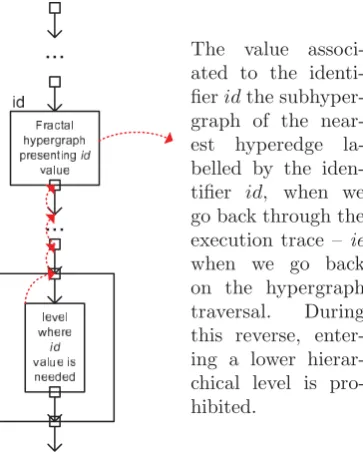
[image:3.595.304.547.157.207.2]The value associ-ated to the identi-fier𝑖𝑑the subhyper-graph of the near-est hyperedge la-belled by the iden-tifier 𝑖𝑑, when we go back through the execution trace – ie when we go back on the hypergraph traversal. During this reverse, enter-ing a lower hierar-chical level is pro-hibited.
Figure 1: Embedding environment into fractal hypergraph
Notice that a lookup function is required. This function takes as argument an identifier and returns the expected result. If the identifier designates a variable, this function returns its value. If the identifier is associated to a func-tion or a method, it returns the fractal hypergraph that represents its closure.
Definition 3 Asystem state is represented by :
∙ 𝑡 : the current time ;
∙ H𝑒 : the hypergraph that denotes the history of the
system execution ;
∙ H𝑠 : the hypergraph representing the whole system.
We define a transition function that maps a system state to another system state.
2.3.2 Some relevant semantics rules
The simplest case consists in the parallel execution of sim-ple instructions.
a
c a
c
b
d Execute
in parallel
Figure 2: Concurrent execution
Execution sometimes depends on a test, corresponding to the dispatch point pattern..
I1 I2 cond c=false cond
c=true c
value I
[image:3.595.310.538.268.329.2]eval(c)
Figure 3: Conditional branching
2.3.3 For information
The whole construction of the C++ programming lan-guage in fractal hypergraphs has already been detailled in [11]. A semantics based onfractal hypergraphof a small behaviour on an intraprocedural language MiniC can be found here [12].
We detail the description of SystemC components and their synchronization through fractal hypergraphs.
3Representing a SystemC component
with Fractal Hypergraphs
The obvious mean to build a fractal hypergraph from a SystemC component is to parse the description into a frac-tal hypergraph, which represents the Control Flow Graph. In this part, we show the translation of some patterns into the corresponding fractal hypergraphs. Note that we will call the set of all possible execution paths Σ.
Sequences are represented by a sequence of hyperedges where each member is labelled by one of the terms of con-junction.
𝑡𝑒𝑟𝑚1 . . . 𝑡𝑒𝑟𝑚𝑁
Figure 4: Sequence of instructions
[image:3.595.88.270.300.527.2]Conditional dispatch points are useful to represent some conditional branching translated from instructions such asif, switch, etc.
𝑐𝑜𝑛𝑑1 . . .
. . . .
[image:4.595.118.208.98.138.2]𝑒𝑙𝑠𝑒 . . .
Figure 5: Conditional dispatch point
{𝑠∈Σ∣𝑠=𝑐𝑜𝑛𝑑1.𝜎1 ∨ ⋅ ⋅ ⋅ ∨ 𝑠=¬(𝑐𝑜𝑛𝑑1∨. . .).𝜎𝑒𝑙𝑠𝑒}
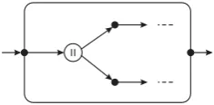
Concurrent dispatch points are useful to represent
[image:4.595.104.222.241.299.2]the creation of several concurrent executions.
Figure 6: Concurrent dispatch point
Loops represent a sequence of iterative actions, such as for loops or while loops. These actions are very useful with automata.
test
c
Figure 7: Conditional guarded loop {𝑠∈Σ∣𝑠=𝜎𝑖𝑛𝑖𝑡.𝜎𝑎𝑐𝑡𝑖𝑜𝑛.(¬𝑡𝑒𝑠𝑡.𝜎𝑙𝑎𝑡𝑒𝑠𝑡.𝜎𝑎𝑐𝑡𝑖𝑜𝑛)∗} ∪
{𝑠∈Σ∣𝑠=𝜎𝑖𝑛𝑖𝑡.𝜎𝑎𝑐𝑡𝑖𝑜𝑛.(¬𝑡𝑒𝑠𝑡.𝜎𝑙𝑎𝑡𝑒𝑠𝑡.𝜎𝑎𝑐𝑡𝑖𝑜𝑛)∗.𝑡𝑒𝑠𝑡.∗}
Synchronized hyperedges SystemC provides a
“wait-/notify” mechanism which plays an important role in the SystemC scheduler [13] and serves as the basic engine of implementing interactions between processes. When mod-elizing the interactions between components, we should also modelize the interaction between processes and so modelize the “wait/notify” mechanism. Synchronized hy-peredgesdenote two kind of hyperedges: hyperedges that wait for some event to be activated as well as hyperedges that activate those events.
Definition 4 A hyperedge E is called a standard hyper-edge, if all the awaited events and all the generated events can only be produced and consumed by synchronized hy-peredges of its embedded fractal hypergraph.
Definition 5 A hyperedgeE is called asynchronized hy-peredge, if one of the following condition is verified :
∙ E may generate an event ; ∙ E may wait for an event ;
∙ there is at least one event generated by an embedded synchronized hyperedge that may be consumed by a synchronized hyperedege that is not located in its em-bedded hypergraph ;
∙ there is at least one event consumed by an embed-ded synchronized hyperedge that may be produced by a synchronized hyperedege that is not located in its embedded hypergraph ;
Synchronized hyperedges or their embedded fractal hyper-graph may also produce or consume events by communi-cating with other synchronized hyperedges.
A synchronized hyperedge E sends all the events that it may generate or that any of its sub-hyperedges may gen-erate to all synchronized hyperedges that are waiting for these events and that belongs to the same fractal hyper-graph asE and to its embedded fractal hypergraph. If a synchronized hyperegde E receives the notification of an event, it will propagate this event to all its synchronized sub-hyperegdes that are waiting for this event.
Objects extends data structures adding member func-tions (also called methods) to those structures. Member functions are easily represented by fractal hypergraphs. Since the environment is embedded, fractal hypergraphs manage both environment and system representation. Fractal hypergraphs provide the values of variables, the closures of functions and the execution traces in the mean-time. An additional function will be necessary. This func-tion takes as argument an identifier and must return the expected result. If the identifier corresponds to a variable, this function will return its value. If the identifier is as-sociated to a function, it will return a fractal hypergraph representing the closure of the function.
Value hyperedges are hyperedges embedding a fractal hypergraph that defines a value.
value
Figure 8: Value hyperedge Data structures, such as
arrays or records, can be defined as different ables embedded in a vari-able. Arrays need their index as identifiers, while records need their field names as identifiers.
value of field1
value of field2
field2 field1
Figure 9: Date structure
In fractal hypergraphs defining a variable is just labelling a hyper-edge, that embeddes its value, with the variable identifier.
value
Id
Figure 10: Variable location
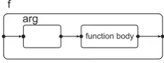
Functions are represented by a fractal hypergraph
arg
function body
[image:5.595.299.550.46.189.2]f
Figure 11: Function hyperedge
Lookup function must find the hyperedge labelled by
its identifier. With data structures, the search function then enters into the hyperedge. By the same way, the search function will find the hyperedge of the embedded fractal hypergraph, that is labelled by the field identifier – field name for records, index for arrays, attributes or methods for objects.
Template is an abstract construction of the C++ lan-gage, which enables to use generic programming. Tem-plates can have value, class or simpler types in arguments. In SystemC, templates enable parametrizing components with values or other components. Template management consist of two steps : the template declaration and the template instantiation.
Step 1 – Template declaration
At beginning a template declaration, we create a fractal hypergraph in order to embed the template representa-tion. It consists in an entry hyperedge, an exit hyperedge and a content hyperedge which aims at embedding the template representation. At this moment, the context hy-peredge contains an empty subhypergraph.
Each times an instance of a template argument class is encountered, we check whether a new public method or public attribute is used. In this case, we add the external fractal hypergraph representing this public method – re-spectively attribute – to the content hyperedge.
At the end of this template declaration, we also have in-ferred the minimal interface that a template argument must respect to be used as an argument of this template. This minimal interface describes all public methods and attributes used in this template declaration.
Step 2 – Template instantiation
The first this template is instantiated with given argu-ments, a new fractal hypergraph is created to represent this instance. For each template argument, we select the hyperedges representing its used public methods and at-tributes. At this moment, these hyperedges only contains an empty subhypergraph. We also full them with their real content by duplicating the fractal hypergraphs represent-ing these attributes or methods in the template argument – as the template processor does before compilation; see the dotted boxes on the following figure1 :
template<cl a s s TValue> cl a s s Value {
public:
TValue arg ;
void f 1 (int n ) { /∗ . . . ∗/ } void fT ( TValue t ) { /∗ . . . ∗/ } }
1Static members are not represented, but can easily be managed
f1 fT
body n
int type
of T type
of T
f1 fT
body n
int T
T t
Value<T> Value
Instantiatiation
Figure 12: Template instantiation
Note Since we infer a fractal hypergraph representing the minimal interface of each template argument, using fractal hypergraph in a template processor enables check-ing contracts at this step of the compilation. This is a major difference with a C++ compiler whose template processor only does a syntaxtic work at template instan-tiation and lets the compiler checks for errors later. This method has a drawback : errors are detected after having modifying the original source code. The error messages are also quite difficult to read given the potential com-plex template nesting used in the source code. Since our method does not aim at only producing a new source code, we have to keep semantical information about templates during their construction. Our template management can also be used in compilation to provide clearer error mes-sages when templates are used, as theC++ conceptswish.
4 Connecting Fractal Hypergraphs
In SystemC, components aggregates subcomponents. The aggregation of the components may be statically defined but can also be dynamically defined. However, connect-ing components is done dynamically. In the same way, associating components to signals and events is also done dynamically. In this section, we present how those opera-tions impact fractal hypergraphs.
binding
/∗ . . . ∗/
com1 . sub com ( com2 ) ;
/∗ . . . ∗/
In SystemC, this instruction binds the component 𝑐𝑜𝑚2 as the sub-component called 𝑠𝑢𝑏 𝑐𝑜𝑚 of the component𝑐𝑜𝑚1.
Here you can see how a sub-component 𝑠𝑢𝑏 𝑐𝑜𝑚 of the component 𝑐𝑜𝑚1 will be initialized with the component
𝑐𝑜𝑚2. At this moment, there are two ways to bind a com-ponent to another one. Binding is a method call in truth. Binding can also be anexternal bindingor an internal/in-lined binding.
[image:5.595.104.221.47.92.2]is used, the processing first calls a function to access to the real component. Then it works with the component. When building the fractal hypergraph representing the binded subcomponent, the processing generates wrappers to connect the internal subcomponent to the external real component. Each call of a subcomponent method goes through a hyperedge embedding a sequence of fractal pergraphs representing the argument values. This peredge goes from the current hypernode to the first hy-pernode of the fractal hypergraphs representing the func-tion body. Then the processing creates another hyperedge from each exit hypernode of the method body hypergraph to the hypernode when exiting function call hyperedge.
f(arg)
arg
function body
f
arg value
{
1. Search
function
returns
arg
function body
f arg
value
f(arg)
2. Then generates
[image:6.595.310.543.49.165.2]the function call
Figure 13: External function call
Given two fractal hypergraphs ℎ1 =
(∅,∅,∅,∅,∅,inV1,outV1,∅,∅) for the
unini-tialized com1.sub com, and ℎ2 =
(V2,H2,inE2,outE2,E2,inV2,outV2,in∂2,out∂2)
for com2, we can define a fractal hyper-graph for the final com1.sub com, as ℎ = (V2,H2,inE2,outE2,E2,inV,outV,in∂,out∂) and :
∙ there exists a relation𝑒𝑛𝑡𝑟𝑦∈ 𝒫(inV ×inV2)
∙ there exists a relation𝑒𝑥𝑖𝑡∈ 𝒫(outV ×outV2)
∙ in∂={(𝑣1, 𝑣2)∈in∂2∣∃𝑣∈inE2, 𝑒𝑛𝑡𝑟𝑦(𝑣, 𝑣1)}
∙ out∂={(𝑣1, 𝑣2)∈out∂2∣∃𝑣 ∈outE2, 𝑒𝑥𝑖𝑡(𝑣, 𝑣1)}
internal binding means the methods to access the sub-component are embedded into the main sub-component. Each call to a subcomponent method is substituted by a hyperedge boxing the body of this method. The fractal hypergraphs representing argument values are then em-bedded into the argument hyperedges. Finally execution trace records the method call and the processing enters the inlined hyperedge.
f(arg)
arg
function body
f
arg value
{
1. Search
function
returns
2. Then inlines
the code
arg
function body
f
value
[image:6.595.40.289.211.341.2]f(arg)
Figure 14: Inlined function call
Given three fractal hypergraphs ℎ1 =
(∅,∅,∅,∅,∅,inV1,outV1,∅,∅) that denotes the wrap-pers that embed the method calls of com1.sub com,
ℎ2 = (V2,H2,inE2,outE2,E2,inV2,outV2,in∂2,out∂2) that denotes the external real sub-component com2, and
ℎ𝑝 = (V𝑝,H𝑝,inE𝑝,outE𝑝,E𝑝,inV𝑝,outV𝑝,in∂𝑝,out∂𝑝)
that denotes the main component com1, we trans-form ℎ𝑝 into ℎ′𝑝 by integrating the description of com2 directly inside the description of com. The final
ℎ′
𝑝 = (V𝑝′,H𝑝′,inE𝑝′,outE𝑝′,E𝑝′,inV𝑝,outV𝑝,in∂𝑝,out∂𝑝) is
defined as follows :
∙ there exists a relation𝑒𝑛𝑡𝑟𝑦∈ 𝒫(inV1×inV2)
∙ there exists a relation𝑒𝑥𝑖𝑡∈ 𝒫(outV1×outV2)
∙ V′
𝑝 =V𝑝′∪V2
∙ H′
𝑝 =H𝑝∖ℎ1
∙ inE′
𝑝={(𝑜, 𝑑)∈inE𝑝 ∣𝑑∕∈in∂1}
∙ outE′
𝑝={(𝑜, 𝑑)∈outE𝑝 ∣𝑜∕∈out∂1}
∙ E′
𝑝=E𝑝∪E2∪ {(𝑑, 𝑜)∣∃(𝑛, 𝑛′),(𝑜, 𝑛)∈inE𝑝∨(𝑛′, 𝑑)∈ in∂2∨𝑒𝑛𝑡𝑟𝑦(𝑛, 𝑛′)}∪{(𝑑, 𝑜)∣ ∃(𝑛, 𝑛′),(𝑛, 𝑜)∈outE𝑝∨
(𝑑, 𝑛′)∈out∂2∨𝑒𝑥𝑖𝑡(𝑛, 𝑛′)}
standard event association
/∗ . . . ∗/
SC METHOD p <<
c l o c k ;
/∗ . . . ∗/
The fractal hypergraph that represents the method 𝑝 is embbeded in a synchronized hyperedge that consumes the
𝑐𝑙𝑜𝑐𝑘event produced by the scheduler.
parallel event association
/∗ . . . ∗/
SC THREAD p <<
c l o c k ;
/∗ . . . ∗/
The fractal hypergraph that represents the method 𝑝 is embbeded in a synchronized hyperedge that consumes the
5 Conclusion
This paper presents a new mathematical structurefractal hypergraphthat can capture the object oriented nature of SystemC components. After providing the mathematical definition of fractal hypergraph and showing how we can define a formal storeless trace-based semantics based on fractal hypergraphs, we introduce how SystemC compo-nents may be represented using fractal hypergraphs; this includes classes, objects as well as template and template instantiation. We also show how the connection between SystemC components or the association of methods de-fined in a SystemC component to an event translate into this fractal hypergraph based representation.
This model based on fractal hypergaphs is successfully used in a SystemC formal debugger [4] and a complete formal SystemC semantics has been defined using fractal hypergraphs.
Since a hyperedge between the vertices of fractal graphs may embed a fractal hypergraph, fractal hyper-graphs can represent complex systems that mix program codes, hardware designs and logical formulae; each hyper-edge of the hypergraph may be either a fractal hypergraph that represent a sequence of instructions (program rep-resentation), a sequence of logical operations (hardware representation), a logical formulae (specifications). We currently are working on static automatic analysis that incrementally replaces an implementation hyperedge with a logical hyperedge: ie. a hyperedge that describes logical formulae. We are also exploring an algorithm that checks if the implementation hyperedge verifies the constraints expressed by a logical hyperedge.
References
[1] F. Drewes, B. Hoffmann, and D. Plump, “Hierar-chical graph transformation,”J. Comput. Syst. Sci., vol. 64, no. 2, pp. 249–283, 2002.
[2] C. Berge,Graphs and Hypergraphs. Elsevier Science Ltd, 1985.
[3] G. Gallo and M. G. Scutella”, “Directed hypergraphs as a modelling paradigm,” Tech. Rep., 1999.
[4] B. Monsuez, F. V´edrine, and N. Vall´ee, “on the de-sign of a formal debugger for system architecture,” in ICC’08: Proceedings of the 12th WSEAS inter-national conference on Circuits. Stevens Point, Wisconsin, USA: World Scientific and Engineering Academy and Society (WSEAS), 2008, pp. 462–467.
[5] B. Monsuez, F. V´edrine, M. Mayero, and N. Vall´ee, “How an ”incoherent behavior” inside generic hard-ware component characterizes functional errors ?” in CISST’09: Proceedings of the 3rd WSEAS interna-tional conference on Circuits, systems, signal and telecommunications. Stevens Point, Wisconsin, USA:
World Scientific and Engineering Academy and Soci-ety (WSEAS), 2009.
[6] C. Colby and P. Lee, “Trace-based program analy-sis,” in POPL ’96: Proceedings of the 23rd ACM SIGPLAN-SIGACT symposium on Principles of pro-gramming languages. New York, NY, USA: ACM, 1996, pp. 195–207.
[7] D. A. Schmidt, “Trace-based abstract interpreta-tion of operainterpreta-tional semantics,”Lisp Symb. Comput., vol. 10, no. 3, pp. 237–271, 1998.
[8] N. Rinetzky, J. Bauer, T. Reps, M. Sagiv, and R. Wil-helm, “A semantics for procedure local heaps and its abstractions,” inPOPL ’05: Proceedings of the 32nd ACMSIGPLAN-SIGACT symposium on Principles of programming languages. New York, NY, USA: ACM, 2005, pp. 296–309.
[9] L. Liquori and M. L. Sapino, “Dealing with explicit exceptions in prolog,” in GULP-PRODE (2), 1994, pp. 296–308.
[10] S. Prasad and S. Arun-Kumar, “Introduction to op-erational semantics,” inThe Compiler Design Hand-book, 2002, pp. 841–890.
[11] F. V´edrine, “Analyses totales de programmes par in-terpr´etation abstraite, application au langage c++,” Ph.D. dissertation, ENS Ulm, 1999.
[12] B. Monsuez, F. V´edrine, and N. Vall´ee, “Creating an adaptative semantics upon fractal hypergraphs,” in waiting for publication, 2010.
[13] B. Monsuez, Y. ZHANG, and F. V´edrine, “Systemc waiting-state automata,” in VECoS’07, Algiers, Al-geria, May 2007.
[14] F. Nielson and H. R. Nielson, “Infinitary control flow analysis: a collecting semantics for closure analy-sis,” in POPL ’97: Proceedings of the 24th ACM SIGPLAN-SIGACT symposium on Principles of pro-gramming languages. New York, NY, USA: ACM, 1997, pp. 332–345.