Abstract—Electric discharge machining is categorized as a thermoelectric process in which heat energy of spark is used to remove material from the work piece. The machining process involves controlled erosion of electrically conducting material by the initiation of rapid and repetitive electrical spark discharges between the tool and workpiece separated by the dielectric medium. The present work is aimed at characterizing the electric discharge machining of maraging steels on EDM. 27 experiments are conducted by varying EDM parameters such as current, pulse-on-time, and duty factor. The performance measures like Material removal rate, surface roughness, and hardness are assessed. It is concluded that metal removal rate, and surface roughness increases with increase in current, duty factor. But, as the pulse-on-time increases MRR and surface roughness decreases. Hardness value increases as the current value increases from 5A to 10A amps and then decreases as the current increases from 10A to 15A. The same effect is observed as in case of duty factor and pulse on-time. Average crack length and recast layer thickness increases with increase in current and duty factor. But, there will be decreasing trend in case of pulse-on-time.
Index Terms— Electric discharge machining, machining parameters, Maraging steel, surface integrity.
I. INTRODUCTION
Electric Discharge Machining(EDM) is a controlled material removal technique where by high frequency electric sparks are used to erode the work piece which takes a shape corresponding to that of the tool electrode. The cutting tool (electrode) is made from electrically conductive material, usually copper or graphite. The electrode made to the shape of cavity required, and the workpieces required are both submerged in a dielectric fluid which is a nonconductor of electricity. A servomechanism maintains a gap of about 0.01m to 0.02m between the electrode and the work, preventing them from coming into contact with each other. A direct current of low voltage and high amperage
1.Associate Professor in Mechanical Engineering
J.N.T.U. College of Engineering, Hyderabad, India Corresponding author E-mail: [email protected],
2. Principal Director, C.I.T.D., Hyderabad, India,
3. Department of Mechanical Engineering, J.N.T.U. College of Engg.,, Hyderabad, India
is delivered to the electrode at a frequency of several KHz producing sparks of similar frequency between the electrode and the work piece through the dielectric fluid. Intense heat is created in the localized area of spark impact, the metal melts or even vaporizes and gets expelled from the surface of workpiece. The dielectric fluid, which is constantly being circulated, carries away the eroded particles of metal during the off cycle of the pulse and also assists in dissipating the heat caused by the spark.
II. LITERATURE SURVEY
A significant amount of work has been focused on ways of yielding optimal EDM performance measures of high metal removal rate (MRR), low tool wear rate (TWR) and satisfactory surface roughness (SR). J.S. Soni and G. Chakraverti [1] have explained the migration of material elements between the electrode and work piece. The work piece used for this investigation is high carbon chromium die steel (T 215 Cr 12). They also studied the scanning electron microscope (SEM) investigation on changes in the chemical composition of resolidified layers of the tool and the work piece as well as debris. The changes in chemical composition often remain confined to within resolidified layer which was supported by others [2]-[3]. O.A. Abu Zeid investigated the role of voltage, pulse-off-time in the electro discharge machined AISI T1 high speed steel [4]. He found that the MRR is not very sensitive to off-time changes at a low pulse-on-time corresponding to finish machining. Volumetric electrode wear has been found to be less with shorter off-times when finish machining but is independent of the off-time and direction of flushing. L.C. Lee, and L.C. Lim investigated the surface transformation and damage in AISI O1, A2, D2, and D6 steels after EDM [5]. According to them the electrical discharge machined surface of all the tool steels generally consists of three distinct layers the out most / white layer, an immediate layer and the unaffected parent layer. Pandey and Jilani [6] presented a thermal model on plasma channel growth and thermally damaged surface layer. They also drew the same conclusion that the EDMed surface has three distinct zones as that of Lee and Lim. Lim et al. [7] provided a review on the metallurgy of EDMed surface, which is dependent on the solidification behavior of the molten metal after the discharge cessation and subsequent phase transformation. The thickness of the recast layer formed on the work piece surface and the level of thermal damage suffered by the electrode can be determined by
Influence of Machining Parameters on
Electric Discharge Machining of Maraging
Steels – An Experimental Investigation
analyzing the growth of the plasma channel during sparking. EDMed surface has a relatively high micro hardness, which can be explained by the emigration of carbon from the oil dielectrics to the work piece surface forming iron carbide in the white layer [8]. The concentration of carbides, both as surface layer on the work piece and as fine debris, is dependent on the frequency and polarity of the applied current together with other processing parameters such as pulse shape, gap spacing, and dielectric temperature [9]. Thompson argued that the pulse duration and type of electrode material under a paraffin dielectric has effect on the amount of carbon contamination [10]. C.H. Kahng and K.P. Rajukar [11] found that the discharge time for the application of fine cutting conditions to improve the surface characteristics should not be estimated on the basis of surface geometry improvement only because the removal of white layer and heat affected zone including cracks requires considerable discharge time. The EDM of advanced ceramics has been widely accepted by the metal cutting industry owing to competitive machining costs and features. Koing, and Dauw [12] classified different grades of engineering ceramics as nonconductor, natural conductor and conductor. Sanchez et al.[13] provided a literature survey on the EDM of advanced ceramics, which has been commonly machined by ultrasonic machining (USM) and laser beam machining (LBM), and proved the feasibility of machining Boron Carbide (B4C) and Silicon infiltrated Silicon Carbide (SiSiC) using EDM and wire electric discharge machining (WEDM). A combination of USM and EDM was also experimented to enhance the dielectric circulation in the spark gap, while machining ceramics with significant improvement in the performance measures and reduction in the thickness of the white layer [14]. A lot of literature is found in case of die and tool steels, ceramics and metal matrix composites. But available literature on super alloys such as Ti-6Al-4V, and maraging steels (M250) is scanty. The present work is concentrated on M-250 which is extensively used in aerospace, automobile, shipbuilding, valves, pump shafts, heat exchangers etc.
III. EXPERMENTAL DETAILS
A number of experiments were conducted to study the effects of the various machining parameters on EDM process. These studies have been undertaken to investigate the effects of current, pulse-on-time, duty factor on the MRR, SR, hardness, and surface structure. The Maraging steel metal is machined with the copper tool. Kerosene is the dielectric medium. 27 experiments are carried by varying EDM parameters such as current, pulse-on-time, and also duty factor while calculating the performance measures like MRR, SR, hardness and surface changes on each work piece. The specification of Maraging steel is M 250 M- stands for high speed steel. The% of carbon in Maraging steel is 0.1%. Other elements are added to get the mechanical and physical strength. The major alloying elements in maraging steel are Nickel, Cobalt, Molybdenum, and Titanium. Maraging steel blocks were cut from the ingots. They were cut in to 27 pieces by tool and turret machine with dimensions of 20mmx8mmx5mm. The experiments were conducted on the
material with copper electrode. Fig.1 depicts the work piece and tool combination.
Fig1: Work piece and Tool
After the initial set up, machining parameters are selected according to the requirement. Dielectric fluid is pumped into the tank above the specimen and then spark is switched on at predefined setting. Before machining each piece, the initial weight of the work is calculated by digital balance. After machining each piece is weighted and difference in weight is the MRR. Surface roughness is measured with talysurf and hardness is measured with Vickers hardness machine. Image analysis system is used to estimate the crack length, and thickness of recast layer of workpieces.
IV. RESULTS AND DISCUSSIONS
[image:2.612.318.538.447.623.2]In the present work the influence of current, pulse on-time, duty factor on the performance indices of EDM such as MRR, SR, hardness and surface changes is evaluated at different experimental conditions.
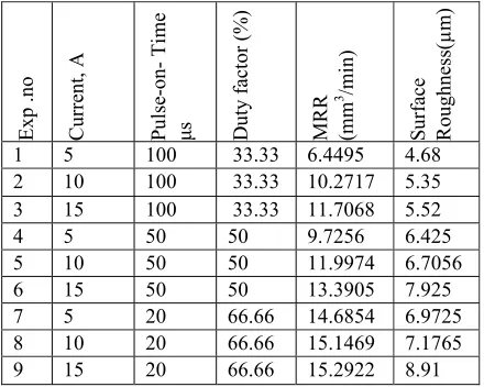
Table I: Variation of MRR with current and SR at constant pulse-on time and duty factor
Exp .no Current, A Pulse
-on- Ti
me
μ
s Duty fact
or
(%)
MRR (mm 3 /mi
n)
Su
rface
Roughness(µm)
1 5 100 33.33 6.4495 4.68
2 10 100 33.33 10.2717 5.35 3 15 100 33.33 11.7068 5.52
4 5 50 50 9.7256 6.425
5 10 50 50 11.9974 6.7056
6 15 50 50 13.3905 7.925
7 5 20 66.66 14.6854 6.9725
8 10 20 66.66 15.1469 7.1765
9 15 20 66.66 15.2922 8.91
the energy of the pulse and ultimately higher metal removal rate. The surface roughness is increased with increase in current. When the discharge current is high, the spark intensity and discharge power are more, subsequently causing a large crater depth on the surface of the work piece, which resulted in high surface roughness value
Table II: Variation of MRR with duty factor at constant current and pulse-on-time
Exp. no Cur
re
nt
A
time
μ
s
Duty factor (
%
)
MR
R(mm
3 /m
in
)
Surf
ace
roughness(µm)
1 5 50 33.33 8.2606 4.225
2 5 50 50 9.7256 4.26
3 5 50 66.66 11.0172 5.70
4 10 20 33.33 9.4325 5.225
5 10 20 50 14.3452 5.45
6 10 20 66.66 15.1469 5.70
7 15 100 33.33 11.7068 5.742
8 15 100 50 21.9256 5.86
9 15 100 66.66 23.8820 6.73
Table II shows the relationship between metal removal rate and duty factor at constant current and pulse-on-time. When duty factor increases at constant current and constant pulse-on-time, material removal rate increases. It is also observed that at constant duty factor the material removal rate also increases with current. It can be noted that, the surface roughness is increased with increase in duty factor from 33.33% to 66.66%. This is due to the fact that at higher duty factor, increase in percent of machining time and increase in total current which automatically increases MRR will occur. Due to faster metal removal rate, surface roughness is increased. It is evident that at lower duty factor we can get good surface finish rather than at higher duty factor.
Table III shows the relationship between metal removal rate and pulse-on-time at constant current and constant duty factor. The metal removal rate is decreased with increase in pulse-on-time. This is because of the short pulses which cause less vaporization, where as, long pulse duration cause the plasma channel to expand. The expansion of plasma channel cause less energy density on the work piece, which is insufficient to melt and/ or vaporize the work piece material. We can observe that, the surface roughness is decreased with increase in pulse-on-time from 20μs to 100μs. When pulse-on-time increases, the intensity of plasma arc decreases. Hence the depth of crater formed in each case decreases resulting in the reduction of surface roughness.
Table III: Variation of MRR with pulse-on-time at constant current and duty factor
Exp.
N
o
C
urrent A
Pulse
-on-time
μ
s
Du
ty
fact
or
(%
)
MRR
(mm
3 /min)
Su
rface
Roughness(µm)
1 5 20 33.33 10.2717 5.165 2 5 50 33.33 9.7256 4.262
3 5 100 33.33 8.5974 4.0867
4 10 20 50 15.1469 5.86
5 10 50 50 14.6574 5.54
6 10 100 50 12.4566 4.87
7 15 20 66.66 19.5866 6.56 8 15 50 66.66 17.6888 5.70
[image:3.612.306.550.81.265.2]9 15 100 66.66 12.7068 4.98
Table IV: Variation of hardness with current at 20μs pulse-on-time and 66.66% duty factor Exp. No Current A Hardness(Hv
)
[image:3.612.343.507.304.367.2]1 5 261.1 2 10 912 3 15 821
[image:3.612.333.519.561.623.2]Table IV shows the relationship between hardness and current at constant pulse-on-time and duty factor. The Vickers hardness value increases from 5A to 10 A and then decreases. When current increased from 5A to 10A more number of carbon particles are deposited on machined surface and hence, the hardness of the machined surface is increased, where as in case of 15A current, due to the high current, the carbon deposited on the machined surface is flushed out. Hence no carbon deposition takes place. Due to this resistance to indentation decreases resulting in the decrease of hardness value.
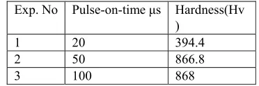
Table V: Variation of Hardness with the Pulse-On-Time at 5A current and 50% duty factor
Exp. No Pulse-on-time μs Hardness(Hv )
1 20 394.4
2 50 866.8
3 100 868
Table VI: Variation of hardness with duty factor at 15A current and 100 μs of pulse-on-time
Exp. No Duty Factor (%) Hardness(Hv )
1 33.33 198.8
2 50 900.3
3 66.66 604.1
Table VI shows the relationship between Vickers hardness and duty factor at constant current and constant pulse-on-time. When the duty factor increases from 33.33% to 50% the hardness value also increases due the deposition of carbon and then, the hardness value decreases at 66.66% due to the high duty factor, at which the carbon deposition layer is flushed out from the work piece.
SURFACE CRACKING
The primary reason for surface cracks in Maraging steel after quenching is the existence of a decarburized layer. The depth of the cracks depends on the depth of decarburization. Immediate tempering after quenching, which prevents surface cracks, is necessary when there is a decarburized
layer. When Maraging steel metal undergoes EDM
operation, high temperature will be generated at the machining surface. When the current increases, the spark intensity also increases. Due to the increase in intensity of spark the temperature of the machining surface will also increases, so that when the current increases the crack length and crack width also increases. When the duty factor increases, the machining time and spark intensity also increases due to which crack length and width are also increases. The cracks are formed with the result of high thermal stresses prevailing at the specimen surface as the latter was cooled at fast rate after the discharge.
(a) (b) ( c)
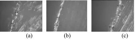
Figure 2: Variation of surface crack propagation at constant pulse-on-time 20µs and duty factor 66.66% by varying current (a) 5A, (b) 10A, (c) 15A with magnification 40 X
Table VII: Variation of Avg. crack length with current at 20μs pulse-on-time and66.66% duty factor Exp. No Current A Average crack
length(µm)
1 5 50.05
2 10 53.52
3 15 64.12
Table VII shows the relationship between average crack length and current. The average crack length is increased with increase in current. When the discharge current is high, the spark intensity and discharge power are more. Subsequently large amount of heat is generated on the surface of the work piece, which results in the thermal stresses developed and exceeds the strength of the material and so average crack length increases. Fig.2 depicts the images of cracks taken at different current values and constant duty factor.
(a) (b) (c)
Figure 3: Variation of surface crack propagation at constant pulse-on-time 100 µs and current 15A at duty factor (a)
33.33%, (b) 66.66%, (c) 50% with magnification 40 X
Table VIII : Variation of Avg. crack length with duty factor at 15A current and 100 µs pulse-on-time
Exp. No Duty Factor (%) Avg. crack length(µm)
1 33.33 51.53
2 50 56.34
3 66.66 64.32
Table VIII gives the values of average crack length at different values of duty factor. Fig.3 depicts the corresponding images taken.
(a) (b) (c)
Figure 4: Variation of average crack length at constant duty factor 50% current 5A by varying pulse-on-time (a) 20 µs
(b) 50 µs, (c) 100 µs with magnification 40 X
Table IX: Variation of Avg. crack length with pulse-on-time at 5A current and 50% duty factor
Exp No.
Pulse-on-time µs
Average crack length(µm)
1 20 35.07
2 50 25.79
3 100 20.69
pulse-on-time. When the pulse-on-time is increased, the intensity of plasma channel expands. Then, the spark intensity and discharge power are less, subsequently causing a less amount of heat generated on the surface of the work piece, which results in thermal stresses developed in the material to decrease, and finally resulting in the reduction of crack length.
RECAST LAYER
Recast layer is a thin layer on the surface of the work piece which is formed when the current from the EDM process melts the material. It heats up the underlying surface and alters the metallurgical structure. The underlying surface is subjected to very sharp temperature gradient. The exact profile temperature gradient depends upon the electrode materials, di-electric and discharge conditions. The recast layer is formed because, some of the molten metal cannot be expelled and has instead been rapidly quenched by the dielectric oil. The EDM process, however, causes Maraging steel to have a recast layer, or heat affected zone, which can result in premature part failure. It also may shorten the life of the part's fine surface finish. The structure of the Maraging steel consists of three distinct layers: Outmost layer, Intermediate layer and unaffected parent metal. The out most layers in Maraging steel is the recast layer which is formed when the out most layers was quenched.
[image:5.612.313.533.48.113.2]
(a) (b) (c) Figure 5: Variation of thickness of recast layer at constant
pulse-on-time 20 µs and duty factor 66.66% by varying current(a)5A, (b) 10A, (c) 15A with magnification 40 X Table X: Variation of thickness of recast layer with current at
20 µs pulse-on-time and 66.66% duty factor Exp.No Current A Thickness of recast layer µm
1 5 22.01
2 10 25.87 3 15 31.34
Table X gives the thickness of recast layer at different current values and fig.5 shows the corresponding images. The experiments were conducted at constant pulse-on-time 20 µs, duty factor 66.66 % and current is varied from 5A to 15A. The thickness of recast layer is measured by image analyzer. The thickness of the recast layer is increased with increase in current, because, more amount of current is available to alter the metallurgical structure of the parent material.
(a) (b) (c) Figure 6: Variation of thickness of recast layer at constant pulse-on-time 100 µs and current of 15A at duty factor (a) 33.33%, (b) 66.66%, (c) 50% with magnification 40 X Table XI: Variation of thickness of recast layer with duty
factor at 15A current and 100 µs pulse-on-time Exp. No Duty Factor (%) Thickness of recast layer µm
1 33.33 25.34
2 66.66 32.56
3 50.00 46.44
Table XI gives the values of thickness of recast layer and the corresponding images at different values of duty factor are shown in fig.6. The experiments were conducted at constant pulse-on-time 100 µs, current 6A and duty factor is varied from 33.33% to 66.66 %. As the duty factor increases the total machining time and percent of total current increases. Higher currents and higher machining times damage the surface material to the higher depths which results in increase in recast layer.
[image:5.612.69.301.359.425.2]
(a) (b) (c) Figure 7: Variation of thickness of recast layer at constant duty factor of 50% current 6A by varying pulse-on-time (a)
20 µs (b) 50 µs, (c) 100 µs with magnification 40 X Table XII: Variation of thickness of recast layer with pulse-on-time at 5A of current and 50% duty factor Exp.N
o
Pulse-on-time µs Thickness of recast layer µm
1 20 56.23
2 50 45.78
3 100 35.78
[image:5.612.313.542.379.445.2]V. CONCLUSIONS
In maraging steel high depth of cuts are possible. When current increases, the MRR also increases. The higher the current, intensity of spark is increased and results in high metal removal rate. When the current is increased, surface roughness is also increased. When current increases, hardness will decrease. When current is increased, the crack length, crack widths are also increased due to the high temperature generation at high currents. When duty factor increases, the MRR is also increases. The higher the duty factor, intensity of spark increases which results in high metal removal rate. When the duty factor is increased, surface roughness is increased. Due to increase in duty factor, the spark intensity, machining time also increases resulting in the increase of MRR. Finally the surface roughness is increases. When duty factor increases, hardness will decrease. When duty factor is increased, the crack length, crack widths are also increased due to the high temperature generation. When pulse-on-time increases, the MRR is decreased. The higher the pulse-on-time, intensity of spark decreases due to expansion of plasma channel and results in less metal removal. When Pulse-on-time is increased, surface roughness is decreased. When Pulse-on-time increases, hardness will increase. When pulse-on-time is increased, the crack length, crack widths are increased due to the low temperature generation at high pulse-on-time due to the expansion of plasma channel. When the pulse-on-time increases the average crack length is decreased. When the current increases the thickness of recast layer increased. When the duty factor increases the thickness of the recast layer is increased. When the pulse-on-time increases the thickness of the recast layer is also decreases.
References
[1] J.S. Soni, G. Chakraverti, “Experimental investigation of migration of material during EDM of die Steel (T215Cr12),” 1994. pp.51-58.
[2] Koshy George, P.K. Philip and Geddam A, “Hardening of surface layers using electrical discharge techniques,” Proc. Conf. 11th AIMTDR, IIT, MADRAS, 1981, p. 315. [3] A. Gandadhar ,M.S. Shunmugam and P.K Philip,
“Surface modification in electro discharge techniques with a powder compact tool electrode,” Wear, Vol. 143, No 1,1991, p.45.
[4] O.A. Abu Zied, “The role of voltage pulse off-time in the electro discharge machined AISI T 1 high- speed steel,” J. of Mat Process Technol. 61, 1996, pp.287-291.
[5] L.C. Lee, L.C. Lim, V. Narayanan and V.C Venkatesh, “Quantification of surface damage of tool steel after EDM,” Vol. 28, No 4, 1988, pp. 359- 372.
[6] S.H. Lee, X.P. Li, “Study of the effect of machining parameters on the machining characteristics in electric discharge machining of tungsten carbide,” Journal of Matl. Processing Technology, 115, 2001, pp.344-358. [7] L.C. Lim, L.C. Lee, Y.S. Wong , H.H Lu,
“Solidification microstructure of electro discharged machined surface of tool steels,” Mater. Sci. Technol, 7, 1991, pp. 239-248.
[8] J.P. Kruth, L. Stevens, L. Froyen, B. Lauwers, “Study of the white layer of a surface machined by die- sinking electro discharge machining,” Ann.CIRP, 44, 1,1995, pp. 169-172.
[9] J.D. Ayers, K. Moore, “Formation of metal carbide powder by spark machining of relative metals,” Metal. Trans. A, 15A, 1984, pp.1172- 1127.
[10] P.F. Thompson, “Surface damage in electro discharge machining,” Mater. Sci. Technol., 5, 1989, pp.1153-1157.
[11] C.H. Kahng and K.P. Rajaurkar, Michnigan Technological University, USA submitted by Prof.M.C. Shaw.
[12] W. Koning , D.F Dauw , G. Levy, U. Panten, “EDM- future steps towards the machining of ceramics,” Ann. CIRP, 37, 2, 1998 , pp.623-631.
[13] J.A. Sanchez, I. Cabanes, L.N. Lopez de Localle, A. Iamaikiz, “Development of optimum electro discharge machining technology for advanced ceramics,” Int J. Avd. Manuf.Technol., 18, 12, 2001, pp.891-905. [14] T.C. Lee, J.H Zhang, W.S. Lau, “Machining of