Abstract — We examine the dynamics of velocity
amplification through pair-wise collisions between multiple masses in a chain, in order to develop very-high acceleration shock-testing machines. A theoretical basis for determining the number and mass of intermediate stages in such a shock amplifier, based on simple rigid body mechanics, is proposed. The influence of mass ratios and the coefficient of restitution on the optimization of the system is identified and investigated. In particular, two cases are examined: in the first, the velocity of the final mass in the chain is maximized by defining the ratio of adjacent masses according to a power law relationship; in the second, the energy transfer efficiency of the system is maximized by choosing the mass ratios such that all masses except the final mass come to rest following impact. Comparisons are drawn between both cases and the results are used in proposing design guidelines. It is shown that for most practical systems, a shock amplifier with mass ratios based on a power law relationship is optimal and can easily yield velocity amplifications of a factor 5-8 times.
Index Terms — multi-body dynamics, impact-testing,
MEMS, shock-amplification.
I. INTRODUCTION
This paper examines the dynamics of velocity amplification through collisions between multiple masses with a view to developing useful machines. The phenomenon of velocity alteration through multiple impacts can be harnessed for uses ranging from shock-amplification to shock-absorption. The dynamics underlying the above are somewhat similar [1], [2]. The current work will focus on velocity amplification and develop a set of rules and guidelines for developing versatile and low-cost machines for very-high shock testing of emerging electronic components like MEMS, nano-optics devices, and sensors.
Due to their small masses, packaged MEMS devices can be designed to be very rugged. They are commonly found in telecommunication equipment with very high reliability requirements; and in critical missile control systems, smart ammunition and in space rockets, where they must be capable of performing reliably under severe acceleration conditions,
Manuscript received March 1, 2008. This work was supported in part by Science Foundation Ireland grant number 03/CE3/I405 and by a grant from the Industrial Development Agency (IDA) Ireland. Acknowledgement is also given to IRCSET (Irish Research Council for Science, Engineering and Technology) for their support of this work.
Brian Rodgers was with the Stokes Institute in the University of Limerick, Limerick, Ireland. He is now with Enterprise Ireland in Dublin, Ireland (e-mail: [email protected]).
Suresh Goyal is with Bell Labs Ireland, Dublin, Ireland (e-mail: [email protected])
Gerard Kelly is with the Stokes Institute in the University of Limerick, Limerick, Ireland (phone: +353-61-233619; e-mail: [email protected]).
Michael Sheehy is with the Stokes Institute in the University of Limerick, Limerick, Ireland (e-mail: [email protected]).
perhaps following a long period of storage. Current test methods used for testing shock-hardened MEMS devices include the Hopkinson bar [3], rail and air guns, very-high drop testing, pneumatic shock and centrifuging [4].
The shock testing machines being proposed in this paper, based on velocity/shock amplification through multiple impacts, offer several advantages over the above methods, including:
• They offer detailed and precise testing capabilities using a single machine that allows a vast range of shock pulses so that shock testing can be incorporated early in the design stage of the device.
• Such machines can be scaled with the size of the object being tested.
• They can be used in stand-alone mode or as attachments to existing shock testing machines, thereby vastly increasing their capability.
• They enable high-speed video recording of the device during test to be implemented relatively easily.
• They provide safer and much lower-cost shock testing capability.
Several other authors have investigated the dynamics of multiple impacts and associated velocity amplification, [5]-[9], as detailed in [10]. The manner in which the current work differs from previous work is primarily in its focus on developing guidelines for building useful machines. Besides gathering all the relevant analytical results from previous work into one place, the novelty centers around the deeper analysis of the various configurations of shock amplifiers mentioned in the paper, comparisons of their relative merits, and the development of design guidelines.
All the analyses presented in the paper are based on simple rigid body models - primarily those governing the momentum transfer and energy dissipation during impacts between two point masses or rigid spheres. These are sufficient because, a) the shock machines being discussed in this paper are designed to ensure independent pair-wise collisions, b) the guidelines being developed are based on velocity amplifications and not acceleration levels so the details of every impact are not important, only the velocities of the masses before and after impact, and c) the general results are valid despite deviations from rigid-body models.
The layout of the rest of the paper is as follows: the dynamics of sequential, pair-wise impacts between a chain of vertically stacked masses is investigated to highlight the ensuing velocity amplification. Optimal design principles for shock amplifiers are then determined followed by discussion and conclusions.
The Dynamics of Shock Amplification
II. VELOCITY AMPLIFICATION THROUGH PAIR-WISE
COLLISIONS
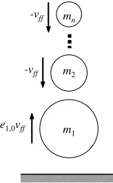
It can easily be shown, as in [10]-[12], that a heavy mass impacting a reasonably light mass, with a sufficiently high coefficient of restitution [11]-[12], can cause a velocity amplification of the lighter mass. For instance in a perfectly elastic collision between two masses that approach each other with equal and opposite velocities, with one of the masses being at least three times as heavy as the other one, the lighter mass rebounds with a velocity that is more than twice its velocity before impact. Building on the above, consider a shock-amplifier made of a vertical stack of masses as shown in Fig. 1 with the masses separated by an arbitrarily small distance from each other.
m1 m2 -vff
mn -vff
e1,0vff
Fig. 1: Model of velocity amplifier prior to second impact
The stack consists of a series of increasing masses with the heaviest mass at the bottom so that
m
1>
m
2> >
...
m
n. Assume that the entire chain is dropped from some height towards the ground such that initially all the masses are approaching the ground with the same free-fall velocity,v
ff. The sequence of events that occurs at impact, in terms of rigid-body mechanics, is as follows.Mass
m
1 impacts the ground first, instantaneously reversing its velocity toe v
1,0 ff (wheree
1,0 is the coefficient of restitution for impacts betweenm
1and the ground) and then impacts the approaching massm
2. With an appropriate2,1
e
and mass ratior
2,1=m
2/m
1, as shown in [10],m
2will reverse its velocity with a magnitude significantly higher than its approach velocity ofv
ff . This phenomenon of velocity amplification through pair-wise impacts continues sequentially asm
2impactsm
3, which then impactsm
4, and so on until massm
n−1impacts the final mass in the chainm
n.It can be shown [10] that the expression for the velocity gain of
m
n, following the sequence of impacts described above, is:(
)
, 11,0
2 , 1
1
1
1
1
nk k n
k k k
e
G
e
r
−= −
⎛
+
⎞
= +
⎜
⎜
⎟
⎟
−
+
⎝
⎠
∏
(1)where
G
n is the ratio of the velocities ofm
nafter and before impact. Equation (1) describes the velocity gain for systems somewhat more general than that explained in Fig. 1, becauseby assuming values of
e
1,0>
1
we have systems where the first mass could hit an ‘active ground’ with the potential for adding energy tom
1.In the following section we examine values of mass ratios and coefficients of restitution that maximize
G
n in a givensystem of masses.
III. MAXIMUM VELOCITY GAIN SYSTEM
It can be shown [10] that for the vertically stacked chain of masses of Fig. 1, and with a constant coefficient of restitution
e
, the velocity gain of the topmost mass can be maximized if the mass ratios obey a power law and it is given as:(
)
1 1
1
1
1
1
nn n
n
e
G
R
− −+
=
−
⎛
⎞
+
⎜
⎟
⎝
⎠
(2)
where
R=m
n/m
1, and the power law for the mass ratios isgiven as: 1
1 , 1
n i i
r
−=
R
−(
i
=
2, 3,..., )
n
(3)A chain of
n
masses with mass ratios specified by (3) is referred to as the Maximum Velocity Gain (MVG) system in the rest of this paper.For perfectly elastic collisions (
e
=
1
), the asymptotic limit for velocity gain whenn
→ ∞
, is given by:2
n nR
G
R
→∞−
=
(4)For inelastic collisions, for every given
e
, ann
maxthat leads to aG
nmaxcan be found directly by tabulating or plotting (2).G
nmaxdecreases with decreasinge
. Fig. 2 illustrates how the velocity gain changes with the number of masses in the chain, the presence of ann
maxand a correspondingG
nmaxand their dependence one
. Note that the maximum velocity amplification achievable through this scheme of multiple impacts decreases rapidly with the increase of energy dissipation associated with every impact, such that for values ofe
<
0.35
there is no velocity amplification at all. Hence for purposes of building a shock-amplifier, it is imperative that the impacts be mediated through materials/methods that have very high restitution.It may also be shown [10] that
n
maxcan be found by using the following method. First determine:( )
( )
*
0
ln
1
ln
R
n
x
=
+
(5)where
x
0 is the solution to the equation:(
) (
)
01 00 0
[image:2.612.142.224.211.344.2]and then calculate:
(
)
(
)
*
* *
1
1
1
1
n
n
e
G
R
−+
=
−
+
(7)The nearest rounded integer (both floor and ceiling) to *
n
that yields a higher value ofG
nthrough equation (7) is thenn
maxand the correspondingG
nisG
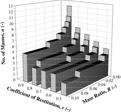
nmax. Fig. 3 shows the value forn
maxcomputed for the range ofe
=
[ ]
0,1
and for a large range ofR
.Total Number of Masses, n (-)
10 100
V
elocity Gain
, G
n
(-)
0 2 4 6 8 10 12 14 16 18
e=1.0
e=0.9
e=0.8 e=0.7 e=0.6
e=0.35
3
e=0.95
e=0.99
Fig. 2: Plot illustrating velocity gain as a function of the number of masses
and the coefficient of restitution, for a vertically-stacked maximum-velocity-gain chain with
R
=
0.012
.0 1 2 3 4 5 6 7 8 9 10 11 12 13
0.00 0.02 0.04 0.06 0.08 0.10 0.5 0.6 0.7 0.8 0.9
N
o
.
o
f
M
a
ss
e
s,
n (
-)
Mass Ratio
, R (-) Coefficient o
[image:3.612.329.525.188.383.2]f Restitutio n, e (-)
Fig. 3: Plot of optimum number of masses to maximise velocity of the
uppermost mass versus mass ratio and coefficient of restitution, for a vertically-stacked maximum-velocity-gain chain system.
While designing a shock amplification machine for testing purposes, design constraints arise from the size of the machine, the size and shape of the objects to be tested, the materials that are available, the required shock levels and their durations, etc. The above, in turn, impose constraints on
R
ande
. Whereas Fig. 2 gives a sense of the velocity amplifications that are possible forR
=
0.012
, Fig. 4 gives a broader picture of the dependence ofG
*(which is very close toG
nmax ) onR
ande
. Fig. 4 shows thatG
*increases monotonically with increasing
e
and decreasingR
. For high coefficient of restitution, the rapid increase inG
*with decreasing mass ratio illustrates how effectively the velocity amplification principle can be utilized for building powerful shock amplifiers.0 2 4 6 8 10
0.01
0.1 0.5
0.6 0.7
0.8 0.9
1.0
V
el
o
ci
ty
G
a
in
,
G
*
(-)
M ass R
atio, R
(-)
Coeff icient
of Re stituti
on, e (-)
Fig. 4: Plot of
G
*versusR
ande
, for the maximum-velocity-gainsystem of vertically-stacked masses.
IV. MAXIMUM ENERGY TRANSFER SYSTEM
Since transferring energy from a heavier mass to a lighter mass through impact is the primary basis for the shock amplification being explored here, intuition suggests that a system of masses where all the energy is transferred to the lightest mass would be the most efficient one as a shock amplifier. Such a system composed of a chain of masses where all of them, except the final mass
m
n, come to rest after impact is henceforth called as the Maximum Energy Transfer (MET) system. Assuming a constant coefficient of restitutione
for all impacts, it can be shown [10] that the mass ratios required for a vertically-stacked MET system have to satisfy the condition:1
1, 1
1
1
i k
k
i i i
k
k
e
r
e
=+ +
=
=
+
∑
∑
(
i
=
1, 2,...,
n
−
1
)
(8)For elastic collisions, (8) reduces to:
1,
2
i ii
r
i
[image:3.612.78.288.201.397.2] [image:3.612.89.282.448.626.2]For inelastic collisions (
e
<
1
), it can be shown by induction that (8) reduces to:1
1, 2
1
ii i i
e
e
r
e
+
+ +
−
=
−
(
e
<
1;
i
=
1, 2,...,
n
−
1
)
(10)Further manipulation of (10) reveals that for larger values of
i
, it quickly reaches a limit given by:1,
lim
i ii→∞
r
+=
e
(11) Unlike with the power law in the MVG configuration, the mass ratios in the MET configuration are not the same along the chain and do not depend onR
, i.e. the ratio of the first and the final mass. Instead, as shown by (8), (9) and (11), the mass ratios depend one
. Fig. 5 plots the mass ratios to illustrate their dependence one
.Mass Number, i (-)
2 3 4 5 6 7 8 9 10
Ma
ss Ra
tio,
ri,
i-1
(-)
0.0 0.2 0.4 0.6 0.8 1.0
e=1.0 e=0.9 e=0.8
e=0.7
e=0.6
e=0.5
e=0.4
e=0.3
e=0.2
e=0.1
Fig. 5: Pair-wise mass ratios
r
i i, 1− versus mass number for varyingcoefficient of restitution in a vertically-stacked MET configuration.
The velocity gain for the uppermost mass of the vertically-stacked MET can be derived to be:
1
n k n
n
k ff
V
G
e
v
==
=
∑
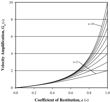
(12)It is clear from(12)that unlike the MVG system, for the MET system the velocity gain of the uppermost mass increases monotonically with
n
ande
. For elastic collisions, (12) reduces toG
n=
n
. Although this implies that velocity gain increases without limit for elastic collisions, it is also clear from (12) that with inelastic collisions the achievable velocity gain from a chain of vertically-stacked masses is limited, withG
n quickly approaching a limit given by:max
lim
1
n n
n
e
G
G
e
→∞
=
=
−
(13)Equation (13) implies that in a vertically-stacked MET system, velocity gain (i.e.,
G
n>
1
) is only achievable if0.5
e
>
. (Note that this is higher than the requirement for an MVG system where velocity gain can be attained as long as0.35
e
>
). Equation (12) is plotted in Fig. 6, for masses ranging from two to ten in the chain, to further illustrate that for values ofe
significantly less than 1,G
nmaxis modest andachieved with fairly short chains. For more dramatic velocity gains that realize the benefit of somewhat longer chains, it is necessary to have high values of
e
.Fig. 7plots the mass ratios
m m
i 1 to illustrate how it can be used along with Fig. 6 to facilitate the design of a vertically-stacked MET shock amplifier. For instance ifm
n,1
m
ande
are known, the mass ratiom m
n 1 can be calculated, and identified as a point on the appropriatee
[image:4.612.93.239.257.392.2]curve in Fig. 7. All the mass ratios higher than
m m
n 1, and corresponding to integer points for mass number, are the mass ratios to be used for intervening masses in the vertically-stacked MET chain. If onlye
andm
1 are known, but a certainG
n is desired, the number of masses needed in the chain can be figured out from the appropriate curve in Fig. 6 and their mass ratios from Fig. . An example is illustrated in Fig. 7, determining the number of masses for a machine withR
=
0.1
- in this case the nearest whole number is 4.Coefficient of Restitution, e (-)
0.0 0.2 0.4 0.6 0.8 1.0
Vel
o
cit
y
A
m
p
lif
ic
a
tio
n
,
Gn
(-)
0 2 4 6 8 10
n=2
[image:4.612.330.523.306.485.2]n=10
Fig. 6: Velocity amplification of the uppermost mass in vertically-stacked
MET chains, consisting of two to ten masses, as a function of coefficient of restitution.
Mass Number, i (-)
2 4 6 8 10
Mass
Ra
tio
,
mi
/m
1
(-)
0.00 0.05 0.10 0.15 0.20 0.25 0.30 0.35
e=0.5
e=0.8
e=1.0
Fig. 7: Plot of mass ratio
m m
i 1versus mass number for varying [image:4.612.333.522.523.699.2]V. THE OPTIMAL DROP TESTING CONFIGURATION
Given that both MET and MVG systems are capable of providing very significant velocity amplification in a vertically-stacked configuration, the next issue is whether there are regions in ‘design space’ where one of them is more optimal over the other for a practical shock amplifier. Generally the design goals for a vertically-stacked shock amplifier are to maximize the velocity gain for the top-most mass while minimizing the total mass in the system for a given
R
ande
. The proposed amplifier consists of a series of successively smaller masses stacked vertically and dropped on a rigid surface such that a sequence of impacts occurs between the masses and the uppermost mass achieves a large gain in velocity. In practice the masses will be guided using linear bearings running on rods so that motion is confined to the vertical axis.Accordingly, Fig. 8 compares the velocity gain and the total system mass respectively for a very large range of
R
ande
(i.e., a large part of the practically encountered design space) for the MVG and the MET configurations. The comparisons are done by normalizing the values of the above three metrics for the MVG system by the corresponding values for the MET system. Note that for any givenR
ande
in these figures, the values of
G
nandM
for the MVG system are those of an optimal configuration, i.e., the MVG configuration that yieldsn
maxandG
nmaxfrom (5)-(7), and for the MET configurations from (8)-(12). In addition, the plotted values ofR
are dictated by the MET system so they fall on the curve dictated by (8).Examination of Fig. 8 and Fig. 9 leads to the main conclusion of this paper: the MVG configuration is more
optimal than the MET configuration. Not only does the MVG
configuration provide higher velocity gain and lower system mass, it is effective over much larger ranges for
R
– even for very small values ofR
. The improved performance of the MVG system is even more pronounced for lower values ofe
, which could be beneficial as the restitution of an actual shock amplifier might degrade over time.Note that the guidelines presented above are general; the design of an actual shock amplifier should be determined after evaluating both MVG and MET models.
VI. CONCLUSION
This paper examined the dynamics of velocity amplification through pair-wise collisions between multiple masses in a chain, with a view to developing useful shock amplification machines for testing small and very-rugged components like MEMS. All the analyses presented in the paper were based on simple but sufficient rigid body models - primarily those governing the momentum transfer and energy dissipation during impacts between two point masses or rigid spheres.
The design and performance of a shock testing machine consisting of a chain of monotonically decreasing masses (heaviest mass at the bottom) that is dropped from some height onto a high-restitution surface, was analysed in detail. In particular it was shown that vertically-stacked shock amplifiers with mass ratios (between the masses) governed
by a power law are ideal, in the sense that they yield the highest velocity gain in systems with reasonably high coefficients of restitution. In addition, these shock amplifier designs are optimal for very large ranges of the mass ratio between the lightest mass (carrying the object under test) and the heaviest mass and can deliver velocity amplifications for coefficients of restitution that barely exceed 0.35.
0 1 2 3 4
0.001 0.01
0.1
0.4 0.5 0.6 0.7 0.8 0.9
R
a
tio
o
f
V
el
o
ci
ty
G
a
in
s,
Mass Rat
io, R (-)
Coefficient of Restitution , e (-)
Fig. 8: 3D plot of ratio (MVG/MET) of velocity gains versus coefficient of
restitution and mass ratio. The velocity gain for the MVG system is that of the optimal MVG system for the given
R e
,
.0.0 0.5 1.0 1.5
0.001 0.01 0.1 0.5
0.6 0.7 0.8 0.9
R
a
ti
o
o
f
T
o
ta
l
S
y
ste
m
M
a
ss
es
,
Mass Ratio
, R (-)
Coe fficient o
f R estitutio
n, e (-)
Fig. 9: 3D plot of ratio (MVG/MET) of total system masses versus
coefficient of restitution and mass ratio. The total mass for the MVG system is that of the optimal MVG system for the given
R e
,
.The shock amplification configurations investigated in this paper are fairly simple, designs that would lead to straight-forward machines. If higher velocity amplification is desired than that attainable with the above machines, other features can be added. For instance in the vertically-stacked configuration, the restitutive surface that the masses drop onto could be ‘active’, i.e., it adds net energy to the system; the initial velocity of the uppermost mass could be made higher than that of the other masses, etc. The analysis of the above scenarios is very much in the scope of the methods presented in this paper.
[image:5.612.317.538.143.318.2] [image:5.612.320.533.363.543.2]building launchers and shock amplifiers, significantly decreasing the size or the form factor of current shock-testing machines, for building protective armor and energy absorbers, for increasing the efficiency of energy harvesters, etc. Particularly in the area of shock testing of emerging opto-electronic components like MEMS & nano-scale devices, that are inherently very rugged or being used in space and military applications, the shock amplifiers described in this paper provide a low-cost, versatile, safe, detailed, precise and observable alternative to the currently practiced ballistic and other methods.
In upcoming papers, the design, construction and performance details of shock amplification machines built using the above principles will be presented. Challenges around the shaping of very-high acceleration shock pulses will also be addressed.
REFERENCES
[1] S. Goyal, J. Papadopoulos, and P. Sullivan, “Shock Protection of Portable Electronic Products: Shock Response Spectrum, Damage Boundary Approach, and Beyond”, Shock and Vibration, Vol. 4, No. 3, 1997, pp. 169-191.
[2] S. Goyal, J. Papadopoulos, and P. Sullivan, “The Dynamics of Clattering I: Equation of Motion and Examples”, Journal of Dynamic Systems Measurement Control, Vol. 120, 1998, pp. 83-93.
[3] V. Bateman, F. Brown, and N. Davie, N, 1996, “Use of a Beryllium Hopkinson Bar to Characterize a Piezoresistive Accelerometer in Shock Environments”, Journal of the Institute of Environmental Sciences, Vol. 39, No. 6, 1996.
[4] S. Zhang-Shu, “Survey on High-G Testing Methodology” [Online], available:http://www.empf.org/empfasis/june05/g0605.htm
[accessed 10 August 2006].
[5] J. B. Hart and R. B. Herrmann, R.B., “Energy Transfer in One-Dimensional Collisions of Many Objects”, American Journal of Physics, Vol. 36, 1968, pp. 46-48.
[6] W. G. Harter, “Velocity Amplification in Collision Experiments Involving Superballs”, American Journal of Physics, Vol. 39, 1971, pp. 656-663.
[7] J. D. Kerwin, “Velocity, Momentum, and Energy Transmissions in Chain Collisions”, American Journal of Physics, Vol. 40, 1972, pp. 1152-1157.
[8] P. Patrício, “The Hertz Contact in Chain Elastic Collisions”, American Journal of Physics, Vol. 72, Issue 12, 2004, pp. 1488-1491.
[9] T. Pöschel and N. Brilliantov, “Extremal Collision Sequence of Particles on a Line: Optimal Transmission of Kinetic Energy”, Physical Review E, Vol. 63, 2001.
[10] B. Rogers, S. Goyal, G. Kelly, and M. Sheehy, “The Dynamics of Multiple Pair-Wise Collisions in a Chain for Designing Optimal Shock Amplifiers”, Bell Labs Technical Report, Murray Hill, NJ, March 2007.
[11] R. M. Brach, Mechanical Impact Dynamics – Rigid Body Collisions, John Wiley & Sons, 1991.