Abstract—This paper presents a new method for the control of Two link- robotic manipulator systems using Linear-Quadratic-Gaussian (LQG), in This method Linear-Quadratic-Linear-Quadratic-Gaussian (LQG) that is a modern state-space technique for designing optimal dynamic regulators by kalman used for the control of Two link- robotic manipulator systems. The simulation result are very promising.
Index Terms— Two link- robotic manipulator systems, using Linear-Quadratic-Gaussian controller, optimal dynamic regulators.
I. INTRODUCTION
In the recent years using intelligece control such as fuzzy control, Neural Network, Neuro Fuzzy and because that they can control nonlinear systems that would be difficult or impossible to model mathematically. In the recently years In Dynamic control of robot have been utilized in many researchers work in this area. Such as Lianfang Tian et al use a neural network approach for the motion control of constrained flexible manipulators robots [1],
Yi , et al have investigated the robustness and stability of a fuzzy logic controller applied to a robotic manipulator with uncertainties such as friction, unmodeled dynamics, and external disturbance etc [2], Kumbla et al have implemented hierarchical control on robotic manipulator using fuzzy logic [3].
Bannerjee, et al have used a Fuzzy Logic Controller to achieve position control of a two-link manipulator [4]. Adams, et al [5] have used GA to optimize the membership functions and rule bases of a multi-stage fuzzy PID controller with a fuzzy switch ror robot control. Brudka, et al presented an intelligent robot control system which employs ultrasonic distance measurements, And for Consecutive stages of data processing they used to neural networks applications [6], Adamiv, et al used neural networks application for mobile robot control on predetermined trajectory of the road [7], Ya-Chen , et al used an Fuzzy neural adaptive controller to multiple-link robot control [8], Devendra P, et al used the proportional plus derivative (PD) control with the PD controller gain parameters optimized via Genetic Algorithm
Leila Fallah Araghi, PhD Student, Electrical Eng. Dept, Tehran Research Science Azad University , Tehran, Iran (corresponding author to provide phone: e-mail: [email protected]).
M. Habibnejad Korayem, Professor, Electrical Eng. Dept, Tehran University of science & technology, (e-mail: [email protected]).
Amin Nikoobin, Assistant Professor, Electrical Eng. Dept, Tehran University of science & technology (e-mail: [email protected]).
(GA) And Fuzzy Logic for control of Two link- robot [9], Z.G. Zhang, et al report on the design and stability analysis of a simple quadruped running controller that can autonomously generate steady running with good energy efficiency and suppress
such disturbances as irregularities of terrain [10], Dongbing Gu, et al presented a new path-tracking scheme for a car-like mobile robot based on neural
predictive control, they employed A multi-layer back-propagation neural network to model non-linear kinematics of the robot instead of a linear regression estimator in order to adapt the robot to a large operating range [11], Mathew L, et al studied on the implementation of several
Intelligent control techniques as applied to the balancing of the inverted wedge problem. These included a basic four-input direct fuzzy controller (including the use of the nonlinear input term) and an adaptive fuzzy control technique known as the FMRLC [12].
Lawrence J. Alder, et al developed a new approach to identification is That utilizes a nominal controller in order to isolate the dynamic effects related to the uncertain parameters from the other known system dynamics[12], John L Meyery, et al presented the results of positive position feedback (PPF) control and linear–quadratic Gaussian (LQG) control for vibration suppression of a flexible structure using piezoceramics [13],
In this paper Two link- robotic manipulator systems is controlled, The problem statement is given in section II In section III LQG controllers is proposed. Simulation results are given in section IV. Finally section V includes conclusions,
II. DYNAMIC EQUATION OF TWO LINK- ROBOTIC MANIPULATOR SYSTEMS [12]
In this section we derive the equations of motion for an individual link based on the direct method has been derived, i.e. Newton-Euler Formulation. The motion of a rigid body can be decomposed into the translational motion with respect to an arbitrary point fixed to the rigid body, and the rotational motion of the rigid body about that point. The dynamic equations of a rigid body can also be represented by two equations: one describes the translational motion of the centroid (or center of mass), while the other describes the rotational motion about the centroid. The former is Newton's
Linear-Quadratic-Gaussian (LQG) Controller
for Two link- robotic Manipulator Control
equation of motion for a mass particle, and the latter is called Euler's equation of motion.
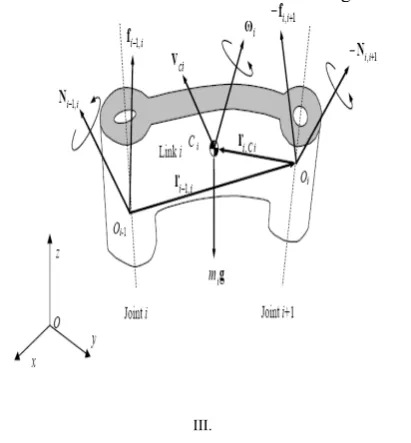
Figure 1 shows all the forces and moments acting on link i.
III.
Fig. 1: Free body diagram of link i in motion
Let be
V
ci the linear velocity of the centroid of link i with reference to the base coordinate frame O-xyz, which is an inertial reference frame. The inertial force is then given byci i
V
m
.
−
, wherem
i is the mass of the link andV
ci.
is the time derivative of
V
ci.Based on D’Alembert’s principle, the equation of motion is then obtained by adding the inertial force to the static balance of forces in eq.( 1) so that
.
1 , ,
1
−
++
−
=
0
− i ii i i ci i
f
m
g
m
V
f
,i
=
0
,
1
,...,
n
(1)
i i
f
−1, and−
f
i,i+1are the coupling forces applied to link i by links i-1 and i+1, respectively, and g is the acceleration ofgravity.
Adding these terms to the original balance of moments we have:
0
)
(
)
(
)
(
1, , 1, , , 1 .1 , ,
1
−
+−
−−
×
−+
−
×
+−
−
×
=
− i ii i i ici i i ici ii i i i i i
i
N
r
r
f
r
f
I
I
N
ω
ω
ω
(2)
i i
N
−1, and−
N
i,i+1are the moment applied to link i by links i -1 and i+1, respectively.If we consider two individual links robot, Let us obtain the Newton-Euler equations of motion for the two individual links.
IV.
Fig.2: Mass properties of two planar robot
From eq. (1) and (2), the Newton-Euler equations for link 1 are given by:
.
1 1 1 2 , 1 1 ,
0
−
f
+
m
g
−
m
V
c=
0
f
(3)0
)
(
)
(
0,1 0,1 1,1 1,2 1 .12 , 1 1 ,
0
−
N
−
r
×
f
+
r
×
f
−
I
ω
=
N
c (4)Note that all vectors are 2 x 1, so that moment N i-1,i and the other vector products are scalar quantities. Similarly, for link 2,
.
2 2 2
2 ,
1
+
m
g
−
m
V
c=
0
f
(5)0
)
(
1, 2 1,2 2 .22 ,
1
−
r
×
f
−
I
ω
=
N
c (6)To obtain closed-form dynamic equations, we first eliminate the constraint forces and separate them from the joint torques, so as to explicitly involve the joint torques in the dynamic equations. For the planar manipulator, the joint torques τ1 and τ2 are equal to the coupling moments:
i i i
N
−1,=
τ
(7) Substituting eq.(7) into eq.(6) :0
)
(
)
(
1,2 2 2 . 2 2 .22
−
×
−
−
ω
=
τ
r
cm
V
cm
g
I
(8)Similarly, eliminating
f
0,1 yields,
(
)
(
)
(
)
(
)
0
.
1 1 2 1 , 0 .
1 1 , 0 2 2 1 , 0 .
1 1 1 ,0 2
1
−
τ
−
×
+
×
+
×
+
×
−
ω
=
τ
r
cm
V
cr
m
V
cr
cm
g
r
m
g
I
(9)Next, we rewrite
V
ci,ω
ci andr
i−1,iusing joint [image:2.595.63.269.129.351.2]that
ω
2 is the angular velocity relative to the base coordinate frame, whileθ
2 is measured relative to link 1. Then, we have. 2 . 1 2 1 .
1
θ
,
ω
θ
θ
ω
=
=
+
(10) The linear velocities can be written as⎥
⎥
⎥
⎦
⎤
⎢
⎢
⎢
⎣
⎡−
=
)
cos(
)
sin(
1 . 1 1 1 . 1 1 1θ
θ
θ
θ
c c cl
l
V
(11){
}
{
}
⎥
⎥
⎥
⎥
⎦
⎤
⎢
⎢
⎢
⎢
⎣
⎡
+
−
+
+
+
−
+
+
−
=
. . 2 2 1 2 1 2 1 2 1 1 . . 2 2 1 2 1 2 1 2 1 1 2)
cos(
)
cos(
)
cos(
)
sin(
)
sin(
)
sin(
θ
θ
θ
θ
θ
θ
θ
θ
θ
θ
θ
θ
θ
θ
c c c c cl
l
l
l
l
l
V
(12) 1 . 2 . 1 . 2 2 12 .. 1 111
=
H
θ
+
H
θ
−
h
θ
−
2
h
θ
θ
+
G
τ
(13)2 . 1 .. 1 21 .. 2 22
2
=
H
θ
+
H
θ
−
h
θ
+
G
τ
That: 2 2 2 1 2 2 2 1 1 1 2 1 111
m
l
I
m
(
l
l
2
l
l
cos(
))
I
H
=
c+
+
+
c+
cθ
+
2 2 2 1
22
m
l
I
H
=
c+
(14)2 2 2 1 2 2 2
11
m
(
l
l
l
cos(
))
I
H
=
c+
cθ
+
)
sin(
22 1
2
l
l
cθ
m
h
=
(15))
cos(
1 22 2
2
=
m
g
l
cθ
+
θ
G
(16)III. LQG controller [14, 15, 16, 17]
In a typical control system design problem, inputs are a dynamic system to be controlled (plant), a description of the types of inputs to be encountered, and specifications Regarding acceptable values of system errors, i.e., the
difference between desired and Actual responses. What is then required is to design a controller so that the plant controller combination satisfies the specifications. The LQG control is a modern state space technique for designing optimal dynamic regulators. It enables a trade off in performance and control effort, and takes into account process and measurement noise. Linear-Quadratic-Gaussian (LQG) control is a modern state-space technique for designing optimal dynamic regulators, The LQG regulator consists of an optimal state-feedback gain and a Kalman state estimator. The first design step is to seek a state-feedback law that minimizes the cost function of regulation performance, which is measured by a quadratic performance criterion with user-specified weighting matrices, and to define the tradeoff between regulation performance and control effort. The next design step is to derive a state estimator using a Kalman filter because the optimal state feedback cannot be implemented without full state measurement. Since the Kalman filter is an optimal estimator
when dealing with Gaussian white noise, it minimizes the asymptotic covariance of the estimation error. In the optimal feedback control, a gain matrix is sought to minimize a specified quadratic performance criterion J (u) expressed as the integral of a quadratic form in the state vector x plus a second quadratic form in the control vector u, i.e.
dt
Ru
u
Qx
x
u
J
(
)
(
T T)
0
∫
∞
+
=
(17)The weighting matrices Q and R are user-specified and define the trade-off between Regulation performance (how fast
x
(
t
)
goes to zero) and control effort [16,17]. The first)}
cos(
)
cos(
{
)
cos(
1 2 2 1 2 1 11 1
1
m
l
g
θ
m
g
l
θ
θ
l
θ
design step seeks a state feedback law
u
=
−
kx
that minimizes the cost functionJ
(
u
)
. The minimizing gain matrix K is obtained by solving an algebraic Riccati equation [14]. This gain is usually called the LQ-optimal gain. Sometimes, the process seeking the LQ state feedback regulator, i.e. LQ-optimal gain matrixk
, is called Linear Quadratic Regulator (LQR) design. [image:4.595.309.534.151.260.2]It is clear that the LQ-optimal state feedback
u
=
−
kx
is not implemental without full state measurement. However, one can derive a state estimatex
^such thatu
=
−
kx
^remains optimal for output feedback problem. This state estimate is generated by Kalman filter [15] as shown below:Fig.3: Block diagram of the Kalman estimator
Mathematically, the Kalman state estimator can be expressed by:
(18) with two inputs, controls u and measurements
y
0
.Determines the Kalman gain
L
in conjunction with dynamic systems through anAlgebraic Riccati equation. The Kalman filter is an optimal estimator when dealing with Gaussian white noise. Specifically, it minimizes the asymptotic covariance of the
estimation error
^
x
x
−
.To form the LQG regulator, simply connect the Kalman filter and LQ optimal gain K as shown in Figure 5-3.
Figure.4 Block diagram of LQG regulator
This regulator has state space equations:
0
)
(
^^.
Ly
x
Bk
LC
A
x
=
−
+
+
(19)^
kx
u
=
−
(20) In addition to LQG design, a Disturbance Accommodate Control (DAC) design and a hybrid LQG/DAC control system are also studied in this chapter. Hence, nine cases will have to be discussed, which are three control systems, the LQG, the DAC and the hybrid LQG/DAC, in conjunction with three different control models, the MCC model, the SCC model and the SSCC model, respectively. I n this paper LQG regulator has been used for two link- robotic manipulator systems. Figure 5 shows the structure of system that used in this system [16].)
0
(
^^ ^.
x
C
y
L
Bu
x
A
[image:4.595.56.255.392.434.2]T1 q1
T2 q2
LQG Controller LPF
LQG Controller LPF
NOISE
NOISE
IN
[image:5.595.52.288.81.319.2]IN
Fig. 5: structure of LQG regulator for Two link- robotic manipulator systems
IV. SIMULATION RESULT
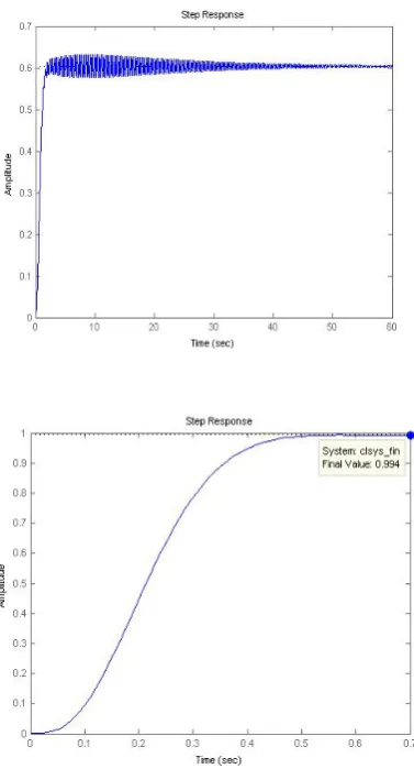
In the first the dynamic model of two link- robotic manipulator systems has been simulated using Matlab software 2007 as you see the system is unstable. Figure 6 shows the schematic of two link- robotic manipulator systems and figure 7 shows the simulation result for step input:
[image:5.595.333.516.85.249.2]Fig. 6: schematic of the two link- robotic manipulator systems
Fig. 7: the output of two link- robotic manipulator systems
As the first method for closed loop control of two link robot the LQG regulator controller has been used, figure 8 shows the simulation result
Fig. 8: the output of two link- robotic manipulator systems using LQG
[image:5.595.333.522.377.727.2] [image:5.595.45.298.537.688.2]V. CONCLUSION
This paper presents a new method for the control of Two link- robotic manipulator systems using method Linear-Quadratic-Gaussian (LQG).
REFERENCES
[1] Lianfang Tian, Jun Wang, and Zongyuan Mao, "Constrained Motion
Control of Flexible Robot Manipulators Based on Recurrent Neural Networks" IEEE TRANSACTIONS ON SYSTEMS, MAN, AND CYBERNETICS—PART B: CYBERNETICS, VOL. 34, NO. 3, JUNE 2004
[2] Yi, S.Y. and Chung, M., J., 1997, “A Robust Fuzzy Logic Controller for Robot Manipulators with Uncertainties”, IEEE Transactions on Systems, Man and Cybernetics, 27, No. 4, pp. 706 – 713.
[3] K umbla, K.K. and Jamshidi, M., 1994, “Control of Robotic Manipulator Using Fuzzy Logic”, Proceedings of the Third IEEE Conference on Fuzzy Systems, Vol. 1, pp. 518-523.
[4] Bannerjee, S. and Woo, P.Y., 1993, “Fuzzy Logic Control of Robot Manipulator”, IEEE Conference on Control Applications, pp. 87-88.
[5] Adams, J.M. and Rattan, K.S., 2001, “Genetic Multi-Stage Fuzzy PID Controller with Fuzzy Switch”, Proceedings of the IEEE International Conference on Control Applications, pp. 323-327.
[6] Brudka, M. Pacut, A., " Intelligent robot control using ultrasonic measurements" Proceedings of the 16th IEEE Instrumentation and Measurement Technology Conference, 1999. IMTC/99.
[7] Adamiv, O. Koval, V. Turchenko, I., “Predetermined movement of mobile robot using neural networks" Proceedings of the Second IEEE International Workshop on Intelligent Data Acquisition and Advanced Computing Systems: Technology and Applications, 2003.
[8] Petropoulakis, L., " Intelligent control using agents and fuzzy behavioural structures" Proceedings of the 2000 IEEE International Symposium on Intelligent Control, 2000.
[9] Ya-Chen Hsu Guanrong Chen Malki, H.A., " Fuzzy neural adaptive controller design: with application to multiple-link robot control" IEEE International Conference on Neural Networks,1997.,
[10] Dongbing Gu and Huosheng Hu., “Neural Predictive Control for a Car-like Mobile Robot” International Journal of Robotics and Autonomous Systems, Vol. 39, No. 2-3, May, 2002
[11] Mathew L. Moore, John T Musacchio1, Kevin M. Passino, “Genetic adaptive control for an inverted wedge: experiments and comparative analyses” Engineering Applications of Artificial Intelligence 2001.
[12] Lawrence J. Alder, Stephen M. Rock, “Adaptive Control of a Flexible-Link Robotic Manipulator” Presented at The American Control Conference, San Fransisco, CA. June 1993.
[13] John L Meyery, William B Harringtony, Brij N Agrawal and Gangbing Song, “Vibration suppression of a spacecraft flexible appendage using smart material” Smart Mater. Struct. 7 (1998) 95–104. Printed in the UK
[14] Dorato, P., Abdallah, C. and Cerone V., LINEAR-QUADRATIC CONTROL. AN INTRODUCTION, Prentice-Hall, In., New Jersey, 1995.
[15] Friedland, B., CONTROL SYSTEM DESIGN, AN INTRODUCTION TO STATE-SPACE METHODS. McGraw-Hill Book Company, 1986. [16] Toolbox, Matlab 2008.