Abstract— Literature on the commercial applications of dielectric industrial drying is plentiful; however, literature on the computations required for estimating dielectric drying power requirements is sparse. Dielectric drying involves several complicated heat and mass transfer phenomena, including absorption of electromagnetic energy, transport of the generated heat, generation of internal vapor, and changes, and changes due to shrinkage. Furthermore, this process involves an assortment of computational expertise, particularly dielectric property characterization. This paper addresses the computational iterations required to estimate the power requirements for unit operation dielectric drying .The objective of the investigation is to explain the theory of the power interaction between dielectric and the drying material. The purpose of this paper is to describe the design calculations for heat energy using microwave power and finally the computation process is applied to corrugated board manufacturing case study to calculate the drying requirement.
Index Terms— Dielectric properties, corrugated board, heating processing, composite material.
I. INTRODUCTION
Escalating energy costs and potential legislation curtailing carbon emissions requires innovative solutions for industrial drying [1]. Dielectric heating I S M and D (Industrial, Scientific, Medical, and Domestic) frequency-based systems allows much wider use by industry to attain higher levels of production efficiency, savings of energy and materials and in some cases to use entirely new methods of production [2].The application of electromagnetic energy for material synthesis and processing is a rapidly expanding field. The success of the microwave oven at 2.45 GHz has led to an explosion of activity, ranging from food processing and medical applications to artificial diamond production and a variety of ceramic applications [3]. Drying of dielectric materials using a continuous microwave has been reported in [4-7]. An important element of microwave drying evaluation is the ability to establish the drying energy required. An understanding of the variation of dielectric properties with temperature and processing state is crucial for simulations and process modeling[8]. Microwaves are electromagnetic waves ranging from 1 m to 1 mm in wavelength. Dielectric heating is a term that covers both radio frequency and microwave systems [9]. Dielectric heating for industry employs two different types of power systems, each covering
Manuscript received March 27, 2009. This work was supported in part by the Australian Government APAI scholarship,Industrial Microwave Process Engineering and Visy Industries.
Abdallah. M. Hasna is the Chair of the Departments of Chemical and Mechanical Engineering at the Higher Colleges of Technology, ADMC, Abu Dhabi, UAE (phone: + 97124048305; fax: +9712 4451571 ; e-mail: ahasna@ hct.ac.ae).
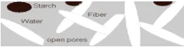
[image:1.595.360.492.374.408.2]a band of frequencies: radio frequencies between 13.56 and 27.12 MHz and microwaves between 896 to 915 and 2450 MHz [10]. Composite materials are now being used across a variety of industries–aerospace, marine and cable applications. Composite materials comprise one or two constituent materials engineered on a macroscopic level to form a useful third material. Many types of composites exist, i.e. fiber-reinforced polymers, carbon-fiber–reinforced plastics, and glass-reinforced plastics, metal matrix composites. The latter is mainly used in Formula 1 car design where carbon-epoxy resins and an aluminum honeycomb core are combined to produce a low-density, high-strength sandwich similarly corrugated board is classified as a composite material non homogeneous mixture with the components loosely packed since it contains paper fibers, starch, air pockets (open pores) and water mixture shown in Fig. 1.
Fig. 1: composite non homogeneous mixture
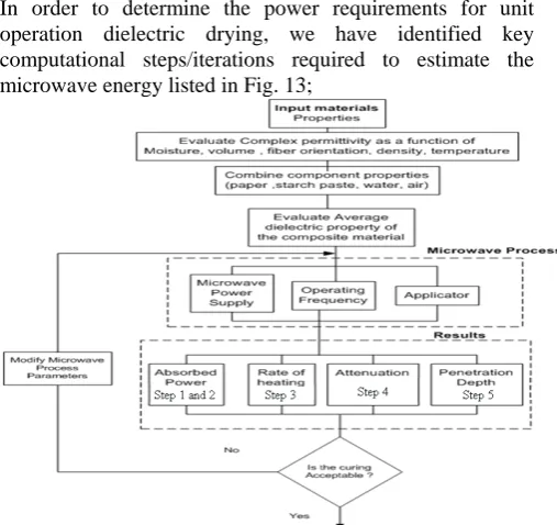
This article presents a framework to calculate the dielectric (microwave) power required for drying of web composite material; by considering the wide number of parameters required for these calculations, a flow chart of the process is illustrated in Fig 2. This sequence of calculations highlights the steps or (iterations) required to determine the (dielectric) microwave energy required for a drying.
II. DIELECTRIC PROPERTY CHARACTERIZATION Several physical procedures are concerned in microwave processing of the composite corrugated fibrous materials. To assess the suitability of a given material for microwave drying, the frequency-dependent relative dielectric constant, are crucial in determining energy transfer i.e. penetration depth, heating rate and the volumetric microwave absorption. Furthermore in order to understand the interaction of microwave energy with a material medium, it is important to accurately know its dielectric property.
Fig 2: Microwave curing of composite material calculations This information is desired in chemical engineering to determine the unit operation of microwave application. Fig 4
Composite Dielectric Heating and Drying: The
Computation Process
[image:1.595.306.548.644.739.2]lists all the possible forms of loss mechanisms, however orientation polarization is perhaps the most significant in microwave curing of corrugated composite at frequencies 2.45 GHz. The distinct feature of starch adhesive curing during microwave processing is the energy conversion or absorption that occurs once introducing the targeted material to an electromagnetic field.
Fig 3: waveguide applicator with composite material
Fig 4: Origin of different types of losses in heterogeneous mixtures containing water [72]
This conversion point is known as gel point, where the interaction rate is proportional to the loss factor of the starch material. It occurs either, through the electric field E (V/m) and the magnetic fields H (A/m), depending on the mode chosen. The permittivity of aqueous solutions or mixtures is reduced by two mechanisms: the replacement of water by a substance with a lower permittivity and the binding of water molecules. When the size of in homogeneities (particles, grains) is much smaller than the wavelength, the effective permittivity of the mixture depends only on the shape of the in homogeneities, not on their size [18].
III. MULTI COMPONENT SYSTEMS
A multi-component system refers to a non homogeneous, non isotropic material, for example microwave drying of corrugated paperboard adhesive involves heat as well as moisture removal from linerboard. In the process the adhesive experiences, a phase change. Thus, a consideration of complex permittivity change with moisture content is needed. It is imperative to revisit the principals governing water presence in liner material. Liquid water has a polar structure, causing it readily to absorb microwave energy and convert it into heat. Once in contact with another material, liquid water is referred to as absorbed water. Absorbed water in wet liner material can exist in two principle states, free water, which resides in capillaries, cavities, etc and bound water, which is chemically combined to other molecules or physically adsorbed to the surface of the material [19]. The majority of industrial materials data available from citied literature particularly [20] suggested dielectric properties at equilibrium moisture. In addition, [21] proposed that the
classical analysis of microwave heating was based on the assumption that absorption rate and the permittivity and permeability of a heated medium are all constant. From the reviewed literature, a range of multi-component analytical expressions for dielectric calculations were found. [22, 23] have proposed relationships between the parameters of dielectric mixtures and volume and loss tangents, these relationships are presented in Equation 1and 2
(1) Ref [24] articulated the most common theory to describe the dielectric permittivity of a heterogeneous mixture are Maxwell-Garnet (MG) theory and the effective medium approximation (EMA). Maxwell-garnet theory was derived based on the polarization induced by externally applied, uniform electric field on isolated spherical inclusions located within the host material, depending on whether air or sample material is considered as the host material (major phase). There are two expressions for the permittivity of the mixture εm as a function of the relative density of sample material.
(3) and when air is considered to be the major phase ,where ε0 and εs are the permittivity of air and sample material respectively [25] the expression is
(4) The Landau and Lifshitz Looyenga [26] model for two-phase mixture requires the determination of the material density. From the bulk density, the volume fractions of the mixture components were determined for use in the dielectric equations parameters calculation, which is described in eqn 5:
(5)
However, once a volume term is added to account for various mixing ratios, the following could also be used to predict the composite materials dielectric property.
Considerations were also given to previous research undertaken by [27] for the analysis of in dielectric properties of agricultural products at various moisture contents. However, in the case of paper and starch adhesive composite, it was difficult to prepare samples to exact dimensions, which is required for permittivity measurements. In addition, it was a complex process to control the penetration rate of the solution into the porous paper liner. Hence, open probe measurements of individual permittivity were taken, and a method of determining the permittivity of the mixture was devised. The relationship incorporated the solid and liquid content of a solution. In this investigation a fractional method of mixtures was expressed, the suggested method utilised percentage volumes of the material to incorporate the dielectric parameters of a multi-component composition where x was the moisture of the solution
(6) IV. FIBER ORIENTATION
[image:2.595.52.279.136.250.2]meter g/m3. Furthermore, in liner material with anisotropic properties, the dielectric constant is largest in the direction of the fiber orientation angle. The coupling between the orientation of polysaccharide chains and electric field implies that the dielectric constant of paper is greater in the planar directions than in the z-direction. [28]studied the influence of fiber orientation or structure on the dielectric properties of paper. It was reported that the orientation in the horizontal plane of the sheet is the result of processing technology. The orientation varies from machine direction to an orientation in any direction; this is shown in Fig. 5. The dielectric properties of paper and board with moisture content up to 30% in the machine direction are 1.4-2.5 times higher than those in the direction perpendicular to the sheet surface.[19]Studied the dielectric properties of paper at various moisture contents, at 27.12 MHz and 2.45 GHz using the same methods proposed by [29] in which the electric field parallel to the plane. The loss factor showed a gradual change with increasing moisture. Measurements on paper with the electric field direction across the plane showed smaller εr’ and εr’’. [30] Reviewed the dielectric properties of paper at various densities and found that the dielectric constant of paper increased with density, ρ. The behavior follows the Clausisi-Mossotti relation as shown in Eqn 7
∝ ρ (7)
Fig. 5: paper structure, with random fiber orientation V. DIELECTRIC PROPERTY MEASUREMENT UNDER
STATIC CONDITIONS
Dielectric properties have a natural variation with frequency, temperature, moisture content and product density [31]. Dielectric measurement techniques include slotted wave guide and standing wave ratio meter, test capacitor assembly, transmission reflection method, open-ended coaxial probe, resonance cavity perturbation technique, and resistance capacitance bridge with a tuned null detector. Literature on dielectric measurement methods is plentiful [32] provided a quality overview of dielectric properties measuring techniques. The dielectric properties of fibrous based products have been studied over a wide range of frequencies using the open-ended coaxial probe method , because it can measure dielectric properties over a wide frequency range, it is easy to use, and it can be used for liquids and solids equally [33-40]. The coaxial probe technique was also used to
measure the dielectric properties of tobacco leaves, beetle shells and other agricultural and
food products [41, 42]. The open-ended coaxial line
[image:3.595.309.548.232.294.2]probe has provided the convenience of nondestructive measurement of the dielectric properties of materials at microwave frequencies.
Fig. 6: dielectric property measurement
[image:3.595.79.276.334.413.2]Fig. 6 shows a schematic diagram of the experimental setup using a coaxial probe for measurement of sample dielectric properties. The purpose of this experiment was such that it was possible to evaluate the average dielectric constant for the composite material so it can be applied in the microwave power calculation. The measurements were obtained using an ANA (automatic network analyzer), open probe method. The technique was pioneered by [36], it calculates the dielectric properties from the phase and amplitude of the reflected signal at the end of an open-ended coaxial line inserted into a sample to be measured. This technique is valid for 915 and 2450 MHz, for materials with loss factors greater than 1 [8, 42]. The open-ended experimental technique utilized a 3.5 mm diameter coaxial line, 4 mm diameter probe, (HP 8714B) with a frequency range of 300 kHz to 3000 MHz.
Fig. 7: Schematic of an open-Ended coaxial Probe
[image:3.595.308.546.381.507.2](t=thickness of composite material 3mm, L length 30 mm) The probe tip shown in Fig. 7 was brought into contact with the substance by touching the probe to a flat face of a solid and by immersing it in a liquid. The measurement was calibrated by measuring the reflection coefficient of from four known standards open, short (copper), water and Teflon.
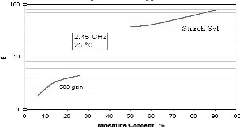
Fig. 8: Dielectric constants at various moisture contents A program developed by FORTRAN software was used to solve for the complex permittivity. The program was run separately for each sample and moisture content. Since water is the major chemical constituent of starch adhesive paste, it is a polar solvent, and the permittivity of free water obeys the so-called Debye model. At low frequencies (static region), where the dipoles have time to follow the variations of the changing electric field, the permittivity is constant and it has the maximum value (ε's, static permittivity).
[image:3.595.307.560.633.776.2]Water at room temperature has a value of ε' close to 80, the real permittivity is also constant at high microwave frequencies (ε'∞, permittivity for infinite frequency), where free water dipoles are unable to follow the rapid field reversals. The value for ε'∞ at room temperature is 4.3. The results shown in Fig. 8, Fig. 9 and Fig. 10 represent the dielectric properties for the corrugated board material. It was found that the moisture content had a direct effect on the dielectric constant of paper. This was due to the significant difference in magnitudes of dielectric constant of ε′ =2-3 in paper and ε′ =80 in water at room temperature at 2.45 GHz. Hence, with a larger percentage of water in paper, the dielectric constant generally increases proportionally. Fig. 8 illustrates the dielectric constants of paper and starch sol at a range of moisture contents.
Fig. 10: Loss factor as a function of temperature 500 gsm The dielectric constants of liner at various grammage, at 25 o
C and 12 % moisture content are shown in Fig. 9. The loss factor calculations incorporate the moisture content of material. For example equation (6) can be applied to determine the dielectric properties of an aqueous solution, by substituting the dielectric constants for starch, paper and water listed in Table 1. The relative value for composites material incorporates percentage volume of various components; hence the effective dielectric constant may be
given by where v is the
volume fraction of the material (v1+ v2+ vn = 1) Relative permittivity at 2.45 GHz
Material Condition ε’ ε’’
Air 1.0006 0
Liner Paper gsm 3.00 0.3
Starch paste 75% water 52.02 4.58
Town Water STP 67.50 6.0075
Table 1: Dielectric properties
VI. CASE ANALYSIS: THE CORRUGATOR PROCESS The most common industrial method for drying corrugated paperboard is by steam heated hotplate. Researchers have previously studied microwave drying of lossy food materials such as frozen food packages. The use of microwave energy to dry low loss materials resembling corrugated paperboard is not very common; though, [17] investigated an alternative method using microwaves, and reported on advantages due to the possibility of heating and drying faster than the hotplate. This case study emphasizes the calculations for microwave drying in a corrugator process. The basic operation of the corrugator is to mould corrugating medium into a fluted structure and paste it onto linerboard. The exposed crowns of the fluted paper are then pasted to another sheet of linerboard. This arrangement is known as a single wall corrugated board
as indicated in Fig. 11. The single wall linerboard glued to corrugated medium , is to be used as a thin dielectric slab.
[image:4.595.49.284.239.350.2].
Fig. 11 : Cross section of the composite material geometry The typical operation of a corrugator is simplified in a flow diagram Fig. 12, Together with an addition of the alternative, microwave assisted curing. Generally, the corrugator combines linerboard and medium into an endless web with a width of web to that of the machine. Due to the continuous nature of the corrugated paperboard starch adhesive drying process, a basis was required to calculate the amount of starch solution (liquid, solids mixtures) for each unit area per treatment time.
Fig. 12 : Corrugator process flow diagram
The classical corrugated paperboard web typically holds 10 grams of starch adhesive paste per square meter (gsm). Further this adhesive starch contains 24% solids. The size of the corrugated paperboard sample is 1000 mm × 44 mm × 3 mm, which is equivalent to the applicator cross section, as indicated in Fig 4. Due to the non isotropic nature of corrugated paperboard composite, a volume distribution calculation yielded 1.32 % starch, 26.80% paper and 71.87 % air.
VII. MICROWAVE ENERGY COMPUTATION PROCESS
[image:4.595.52.288.494.582.2]In order to determine the power requirements for unit operation dielectric drying, we have identified key computational steps/iterations required to estimate the microwave energy listed in Fig. 13;
[image:4.595.305.559.535.774.2]The downward procedure illustrates three major areas material property, microwave process and finally results; the upward procedure illustrates the feedback steps. Hence, the first steps toward computing microwave energy begin with dielectric input material properties which were discussed in the previous section. Hence we use that input into the algorithm shown in Fig. 13 and following the steps to get specific microwave power calculations.
Step 1: Initially to determine the electric field strength; in this experimental setup we will begin using a TE10 waveguide applicator. Hence for or the purpose of the following calculations, a microwave power value of Pi = 1.3 kW and f = 2.45 GHz was used this defined the power threshold for the MW applicator. The case study is based on non-magnetic (μ=1) materials, such as corrugated board materials, from the power balance, Where, Pa= Absorption power, Pt= Transmitted power, power passed through paper, Pi= Incident power=1300 W, Pr= Reflected power, using the Peak Power Equation to determine the electric field strength
(8) By rearranging Eqn. (8) 2.5x10⁴ v/m, however the electric
field within a product is determined by a combination of dielectric properties, the geometry of the product, and by the applicator configuration.
Step 2: Absorbed Power: The power absorbed per unit volume of the corrugated board (W/m3) under the influence of electromagnetic field, is expressed by
(9) Where, E=electromagnetic field strength in V/m, = angular frequency rad/sec, ε0= Electric constant. Hence, PAvg Absorbed =292 W
Step 3: rate of Heating: The heating rate depends on the thermal capacity while absorbed power depends on the dielectric properties of corrugated paperboard composite. Even as microwave energy penetrates the corrugated paperboard composite, two thermal properties determine how the product will be heated (thermal conductivity k, and specific heat capacity Cp). A further two mechanical properties (density for solid, and viscosity for liquid products determine how the product will be heated [43]. [44] recommend that in multi component products, which may have widely differing dielectric and thermal properties, to balance both the thermal and dielectric properties in order to get more even temperature distribution. Usually it is easier to adjust specific heat capacity than the dielectric properties, therefore substituting energy equation into equation 17.
(10) Hence we can determine the rate of heating of the corrugated paperboard composite under the electromagnetic irradiation, where temperature ΔT is expressed as a function of the power absorbed, the time exposure to the microwave energy, the density of the material and the specific heat.
Step 4: Attenuation: The attenuation is defined as the measure of the rate of decay of the electromagnetic field as it propagates through a medium. The attenuation factor 3.11x10-03 was calculated by substituting known values for ε′ and tan2 δ into Equation (11)
(11)
Step 5: Penetration depth : Theoretically, the power penetration depth is the distance from the surface of a dielectric material at which the incident power of a perpendicularly impinging, forward propagating plane electromagnetic wave drops to 1/e, approximately 37 % [45]. In terms, of industrial curing application, the penetration depth gives an indication of the efficiency of heat penetrating the substrate. From transmission line theory the electric field attenuation is given by
(12) Where, Pi is the incident power, P is the power at the
penetration depth,
α
is the attenuation constant, and d is the penetration depth, [45] expressed penetration depth as the half-power depth, (the depth from the surface of a material at which the power has been reduced to one-half the incident power). A model depicting that could be achieved by dp= 1/2.885α. Penetration depth can also be calculated directly from the dielectric properties, for example, if tan δ is smaller than about 0.5, the formula gives 97% to 100% of the correct value [64].Fig.14: Penetration Depth for 2.45 GHz, TE10, (STP) Fig.14 demonstrates the attenuation in power as a function of distance into the material at α=3.11×10-03
. For example, consider a corrugated paperboard sample with a maximum thickness of 3 mm, from Fig.14 the transmitted is approximately ~1.2 kW, which indicates that the signal had sufficiently penetrated the material. Finally we compare between absorbed power and gel point, to test this theory, we simulate the case study conditions. In this section, a comparison between the absorbed power calculated using experimental evaluation dielectric properties and thermal power required to reach gel point at a particular conveyor speed is presented. Consider a continuous corrugated paperboard curing of starch adhesive at 10 gsm, 2.78m wide with a thickness of 3 mm, at 300 m/min. therefore it was necessary to evaluate how much power per unit volume is required to heat it from 18 oC to the adhesive gel point temperature of 63 oC, given the heat capacity of starch 3400 J/kgoC, density of adhesive = 1050 kg/m3. The dimensions of the corrugated paperboard strip inside the applicator, for a length 1 m in (z-direction), a width of 0.044 m, and thickness 0.25×10⁻³
m. Hence, at 10 gsm, the mass of starch per strip equated to 1.848 ×10⁻³
capacity of starch . Therefore curing the composite material with the full power penetration for a minimum of 1 sec per strip of material requires 283 Watts.
Fig. 15: Schematic of paper web travelling a long a belt VIII. DISCUSSION
The principle of microwave heating consists in the transformation of the alternating electromagnetic field energy to thermal energy by affecting polar molecules of a material. The most suitable materials for microwave heating are those with high value of a loss factor, such as liquid water or other polar molecules, i.e. salts, carbon, etc. Materials without a bipolar electric charge do not react to microwaves. In terms of assessing microwave interaction with a composite material, a simple power balance. Once an electromagnetic wave Pi, acts on the composite material, part of the incoming energy is reflected Pr, and part passes through the surface Pt. A certain percentage of the incoming energy is also absorbed Pa. For example, a material with high electrical conductivity subjected to high-frequency radiation acts like a reflector while material with a poor electrical conductivity can be transparent to radiation. Hence, to heat a material volumetrically, the material must absorb some of the radiation. Therefore, the microwave field and the dielectric response of a material govern its ability to absorb heat from microwave energy; this absorption value is correlated to the material complex permittivity. The difference in dielectric properties is contributed to the mechanism, which commands the behavior under microwave. For example, rotation is possible only if the field is parallel to the chain axis. Since the chain, orientations in paper are random, only small fractions of the water molecules have the exact alignment with the electric field. This makes the dielectric constant much smaller than it is with water. In addition, the dielectric constant of paper increases with increasing moisture content. Moisture also significantly influences dielectric losses (the imaginary part of permittivityε″). However, water molecules in paper fibers are associated with polysaccharide chains and cannot rotate freely. Hence Frequency, loss tangent and dielectric constant affect the amount of power that is dissipated in paper in the form of heat. Upon probing the effect of grain direction had on the loss tangent and dielectric constant no distinct pattern was observed, as no one specific grain direction consistently showed markedly higher or lower values when compared to the other two. Grain direction was therefore observed to have no significant affect on the loss tangent or dielectric constant in this study perhaps due experimental discrepancies. For an increase in temperature, the dielectric constant of the paper increases, and the loss factor has a minimum around 60 oC. This is due to the decrease in interfacial polarization and the increase of the dielectric loss due to carboxyl-groups at high temperatures shown in figure 10, Fig. 9, and Fig. 10. [46] Purported three classes of temperature profile in microwave heating. These classes combine penetration depth Dp (the depth at which the power drops to 1/e of its surface value), physical size, heating
time and presence of convective heating at the surface. [47] Developed a correlation between temperature non-uniformity and parameters such as microwave flux, penetration depth and duration of heating when the power deposition can be approximated as simple exponential decay. [48] Presented three classes based on low, moderate and high-loss materials. [49] reported three causes of the deviation away from simple exponential decay in homogeneous substances: impinging wave characteristics [e.g, angle of incidence, type of mode, non-propagating field components], radius of curvature of the workload surface, and internal standing wave phenomena in the workload. [50] listed several ‘rules of thumb’ for predicting microwave-heating pattern, including: calculation of penetration depth, the use of several ovens to determine if the permittivity, geometry or oven characteristics dominate heating patterns, understanding focusing effects in cylinders and spheres as a function of the penetration depth, and understanding thermal runaway in frozen foods. [51] Proposed a classification system for predicating microwave-heating behavior based on applicator type, material, electrical size and microwave controlled field. For material with appropriate dielectric properties, microwave energy offers the composite drying industry a prospect for selective and uniform drying. In context, the corrugated paperboard industry would benefit from selective heating in areas where water is present, due to areas with higher moisture count absorb more microwave power than drier areas, more water is removed from these areas, resulting in a more uniform moisture distribution. This is also known as automatic moisture profile correction. Another desired effect is heating uniformity throughout all magnitudes of the corrugated material, provided that the penetration depth is not less than the material thickness. By comparison to conventional surface heating processes, microwave heating requires no temperature differential to force heat by conduction from the surface to the inner layers. Furthermore, microwave curing presents specific attractions to the corrugated paper board industry. These attractions include uniform heating of paper/starch, depth of penetration through paper web material, power control, competitive operating cost, modular design considerations, finally processing versatility (speed). Preliminary trails of continuous microwave curing experiments of corrugated paperboard adhesive demonstrated that the load consumes power in proportion to its volume. The applicator section, in which the transfer of energy occurs, is where microwave-curing issues commonly arise. The physical dimensions of the applicator section are dependent on the process parameters, batch continuous, frequency and treated material. However, frequently it is slightly wider than the load itself and the length will be a fraction of that of a conventional drier. Special applicator designs may be multi-pass, multi-zone, arched, inclined, horn antennas or vertical. For further references on the topic, refer to [52, 53] .
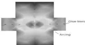
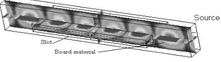
Therefore, 282.7 W of power is required to cure one strip to gel point. Furthermore, an electromagnetic computer simulation using HFSS 5.4 of the applicator and targeted material was undertaken to provide another form of analysis. The specially designed microwave applicator was analyzed using corrugated board as the material to be heated and dried. The three dimensional view of the applicator is shown in Fig. 17 together with the electric field distribution, where the concentration of colors refers to the uneven energy which corresponds to the temperature and field distribution. It is also illustrated the signal from the source penetrates the slot line material, causing energy dissipation in the corrugated material. Another advantage of the simulation was the ability to determine the arcing positions within the applicator. This was simulated and is shown in Fig. 17 and figure 17. Arcing was controlled by changing the size of the slot.
Fig. 17: Simulation of TE10 applicator IX. POTENTIAL APPLICATIONS
[image:7.595.45.292.507.621.2]Microwave treated composites can find a range of potential water proofing applications such as boxed water containers. A photograph of a specially designed microwave drying system is shown in Fig 18, the applicator is illustrated in Fig 3 which is essentially the core of the microwave drying unit operation. It consists of the three following principal elements: the applicator, carrying conveyor and compressing belt. The applicator is a hollow cavity shown schematically in Fig 3 that forms the microwave heating circuit for irradiation where energy is supplied by an electromagnetic field directly to the material it consists of a waveguide section WR340 as the cavity with small slot opening configuration coupling slot, [11-14].
Fig 18: Photograph of microwave drying experimental set-up
X. CONCLUSION
Knowledge of electromagnetic theory calculations and dielectric response are essential to assess the suitability of microwave drying of materials. Although microwave-heating investigations have been researched extensively over the last 30 years, the literature reviewed indicates a void in a simple method to assess suitability. The compilations of equations used illustrate a straightforward technique to compute the energy requirements. The objective of this work was to determine microwave drying key parameter power absorption. In the case study example of corrugated
paperboard it was found that the power required to gelling point per strip of corrugated board to be 283 W , by comparison with an experimental dielectric properties value using Eqn (9) deduced 291.6 W of power absorbed by the composite using dielectric properties. The reported calculations and observations on the corrugated paperboard composite interaction with the electric field present an indication of microwave drying viability.
REFERENCES
[1]. Mujumdar, A.S. and W. Zhonghua, Thermal Drying Technologies Cost-Effective Innovation Aided by Mathematical Modelling Approach. Drying Technology, 2008. 26(145-153).
[2]. Harrison, W.L., Electric power for industrial processes using dielectric heating. Power Engineering Journal, 1988. 2(2): p. 105-113.
[3]. Osepchuk, J., Radio Frequency Safety Issues In Industrial Heating Systems. Ceramic Transactions Microwave Theory and Application Material Processing, 1991. 21.
[4]. Jones, P.L., Dielectric-assisted drying and processing. Power Engineering Journal 1989. 3(2): p. 59-66.
[5]. Schiffmann, R.F., Microwave and dielectric drying, in Handbook of Industrial Drying. 1955, Marcel Dekker, Inc: New York. p. 345-372.
[6]. Zhao, Y., Using Capacitive Radio Frequency Dielectric Heating In Food Processing and Preservation- a review Journal of Food Process Engineering, 2000. 23(1): p. 25-55.
[7]. Rattanadecho, P., et al., Drying of Dielectric Materials Using a Continuous Microwave Belt Drier Case Study: Ceramics and Natural Rubber. Journal of Manufacturing Science and Engineering, 2007. 129(1): p. 157-163. [8]. HP, Dielectric probe kit 85070A, in Hewlett Packard
Corporation, P. Alto, Editor. 1992, Research and Development Unit, Test and Measurements Laboratories: [9]. Jones, P.L. and A.T. Rowley, Dielectric Drying. Drying
Technology, 1996. 14(5): p. 1063 - 1098
[10. Harrison, W.L., Electric power for industrial processes using dielectric heating. Power Engineering Journal, 2002. 2(2): p. 105-113.
[11]. Zlotorzynski, A., The Application of Microwave Radiation to Analytical and Environmental Chemistry. Critical Reviews in Analytical Chemistry1995. 25(1): p.43-
[12]. Thostenson, E.T. and Chou T. -W., Microwave processing: fundamentals and applications, Composites Part A:. Applied Science and Manufacturing, 1999. 30(9): p. 1055-1071.
[13]. Pathak, S.K., F. Liu, and J. Tang, Characterization of a Single Mode. Journal of Microwave Power and Electromagnetic Energy, 2003. 38(1).
[14. Metaxas, A.C., Journal of Microwave Power. Rapid Feasibility Tests Using a TE10n Variable Aperture Resonant Applicator, 1990. 25(1): p. 16-24
[16]. Mudgett, R.E., Electrical properties of foods, in Engineering properties of foods, M.A.a.R. Rao, S.S.H, Editor. 1995, Marcel Dekker: New York. p. 389-455. [17]. Hasna, A.M., Curing Starch Based Adhesives
Microwave or Conventional. Journal of Materials and Product Technology, 2003. 19(1-2).
[18]. Ryynanen, S., Microwave Heating Uniformity Of Multi component Prepared Foods. 2002, University of Helsinki Department of Food Technology: Helsinki.
[19]. Metaxas, A.C. and R.J. Meredith, Industrial Microwave Heating. 4 ed ed. Power engineeringseries. 1983, London, England: peter peregrines.
[20]. Von Hippels, Dielectric materials and applications. Boston. 1954: M.I.T. Press.
[21]. Tran, N., Advances In the modelling of microwave and hot air drying of materials. Ceramic Transactions, Microwave Theory And Application Material Processing IV. Vol. 80. 1997, Florida America Ceramic Society. [22]. Buchner, A., dielectric techniques using mixture of
bodies. 1939: Wiss Ver Siemens
[23]. Trapp, W. and L. Pungs, effects from temperature moisture on dielectric behaviour from natural wood using high frequency. Holzforschung, 1956. 103: p. 65-68. [24]. Landauer, R., Journal of Applied Physics. 1952. 23: p.
779-784.
[25]. Calame, J., The Dielectric Properties of porous zinc oxide ceramics, in Microwave processing of materials symposium proceedings. 1996, materials research society: San Francisco, USA. p. 273.
[26]. Landau, L.D. and E.M. Lifshitz, Electrodinamica, in Sploshnishsred. 1957: Gostehiezdat, Moscow.
[27]. Nelson, S.O., Dielectric properties of agricultural products-measurements and applications. Electrical Insulation, IEEE Transactions on, 1991. 26,(5): p. 845 – 869.
[28]. Torgovnikov, G., Dielectric Properties of Wood and Wood-Based Materials. 1983, Germany: Springer-Verlag.
[29]. Roberts, S. and A. von Hippel, A new method for measuring Dielectric constant and loss in the range of centimeter waves. Journal of Applied Physics, 1946. 17: p. 610-616.
[30]. Leskela, M. and S. Simula (1998) transport phenomena. Paper Physics Volume, 285-317
[31]. Nelson, S.O., L.E. Stetson, and C.W. Schlaphoff, A general computer program for precise calculation of dielectric properties from short-circuited wave-guide measurements. IEEE Transactions on Instrumentation and Measurement 1974. 23(4): p. 455-460.
[32]. Venkatesh, M.S. and G.S.V. Raghavan, An overview of dielectric properties measuring techniques. Canadian Biosystems Engineering, 2005. 47.
[33]. Engelder, D.S. and C.R. Buffler, Measuring dielectric properties of food products at microwave frequencies. Microworld, 1991. 2(11): p. 122.
[34]. Kumar, P., et al., Measurement of Dielectric Properties of Pumpable Food Materials under Static and Continuous Flow Conditions. Journal of Food Science, 2007. 72(4). [35]. Mosig, J.R., et al., Reflection of an open-ended coaxial
line and application to non-destructive measurement of materials. IEEE Trans. Instrument. Measurement,, 1981. IM-30: p. 46-51.
[36]. Stuchly, M.A. and S.S. Stuchly, Coaxial line reflection methods for measuring dielectric properties of biological substances at radio and microwave frequencies: A review,. IEEE Trans. Instrumentation Measurement,, 1980. IM-29: p. 176-183.
[37]. Tran, V., S. Stuchly, and A. Kraszewski, Dielectric properties of selected vegetables and fruits 0.1-10.0 GHz. Journal Microwave Power, 1984. 194: p. 251-8.
[38]. Grant, J.P., et al., A critical study of the open-ended coaxial line sensor, technique for RF and microwave complex permittivity measurements. Journal of Physics: Electronics and Scientific Instrument, 1989. 22: p. 757-770.
[39]. Misra, D., M. , et al., Non-invasive electrical characterization of materials at microwave frequencies using an open-ended coaxial line: Test of an improved calibration technique. IEEE Trans. Microwave Theory Tech, 1990. 38: p. 8-14.
[40]. Stone, D.A. and M.P. Robinson, Total body water measurements using resonant cavity perturbation techniques. Physics in medicine & biology, 2004. 49(9): p. 1773-1788.
[41]. Mashimo, S., et al., Dielectric relaxation time and structure of bound water in biological materials. J. of Physical Chemistry, 1987. 91: p. 6337-6338.
[42]. Sheen, N.I. and I.M. Woodhead, An open-ended coaxial probe for broad-band permittivity measurement of agricultural products. Journal of Agricultural Engineering Research, 1999. 74: p. 193-202.
[43]. Buffler, C.R., Microwave Cooking and Processing. 1993, New York: Van Nostrand Reinhold.
[44]. Buffler, C.R. and M.A. Stanford, Effects of dielectric and thermal properties on the microwaveheating of foods. Microwave World, 1991. 12: p. 15.
[45]. Decareau, R. and R. Peterson, Microwave processing and engineering. 1986, Chichester, England: Ellis Horwood.
[46]. Dolande, J. and A.K. Datta, A Temperature profiles in microwave heating of solids a systematic study. journal of microwave power and electromagnetic energy, 1993. 28. [47]. Lobo, S. and A.K. Datta, characterisation of spatial
non-uniformity in microwave reheating of High Loss Foods. Journal of microwave power and electromagnetic energy, 1998. 33: p. 158-166.
[48]. Peyre, F., A. Datta, and C. Seyler, Influence of dielectric property on microwave oven heating patterns: applications to food materials. Journal of microwave power and electromagnetic energy, 1997. 32.
[49]. Ohlsson, T. and P.O. Risman, Temperature distribution of microwave heating; spheres and cylinders. Journal Microwave Power, 1978. 13 (303-310).
[50]. Buffler, C.R. and M.A. Stanford, Effects of dielectric and thermal properties on the microwaveheating of foods. Microwave World, 1991. 12.
[51]. Bows, R.J., Microwave Heating, International Journal of Food Science and Technology, 2000. 35(417-30). [52]. De Loor, G.P., Dielectric properties of heterogeneous
mixtures containing water. Journal of Microwave Power and Electromagnetic Energy, 1968. 3.
![Fig 4: Origin of different types of losses in heterogeneous mixtures containing water [72]](https://thumb-us.123doks.com/thumbv2/123dok_us/1313558.661517/2.595.50.285.136.392/origin-different-types-losses-heterogeneous-mixtures-containing-water.webp)