Measurement and characterisation of concrete substrate
roughness in patch repairs
GRIGORIADIS, Konstantinos
Available from Sheffield Hallam University Research Archive (SHURA) at:
http://shura.shu.ac.uk/10121/
This document is the author deposited version. You are advised to consult the publisher's version if you wish to cite from it.
Published version
GRIGORIADIS, Konstantinos (2015). Measurement and characterisation of concrete substrate roughness in patch repairs. In: 16th European Bridge Conference,
Edinburgh, 23-25 June 2015. (In Press)
Copyright and re-use policy
See http://shura.shu.ac.uk/information.html
Sheffield Hallam University Research Archive
MEASUREMENT AND CHARACTERISATION OF CONCRETE SUBSTRATE ROUGHNESS IN PATCH REPAIRS
Konstantinos Grigoriadis1,2 1
School of Engineering and Mathematical Sciences, City University, Northampton Square, London, EC1V 0HB, UK
2
Centre for Infrastructure Management, Materials & Engineering Research Institute, Sheffield Hallam University, Howard Street, Sheffield, S1 1WB, UK
KEYWORDS
Concrete, Remote robotic hydro-erosion, Substrate surface roughness, Patch repair
ABSTRACT
Patch repair is one of the most common types of repair in reinforced concrete bridges. The overall success and long-term durability of a patch repair is significantly influenced by the bond developed at the interface between the concrete substrate and the repair material. In turn, the bond strength is influenced by the topography (roughness) of the substrate surface after removal of the defective concrete. However, different removal methods of defective concrete produce substrate surfaces with different topographies. Hence, the ability to measure and characterise the topography of substrate surfaces is of great importance for evaluating the effectiveness of different removal methods. In this paper the effect of two removal methods: electric chipping hammers and Remote Robotic Hydro-erosion (RRH) on the surface roughness is investigated. The paper also presents an alternative to current BS EN 1504-10 surface roughness measurement methods (sand patch and contact stylus profilometry), which overcomes some of their limitations. It employs state of the art fringe-based laser interferometry which provides a more accurate measurement and characterisation of concrete substrate surfaces. In addition, it has the potential for use in other fields of concrete bridge maintenance and rehabilitation where surface roughness is important such as FRP laminate strengthening and application of water proof coatings.
NOMENCLATURE
dz/dx local slope of the surface profile
L evaluation length along the x axis (mm)
Lo actual profile length (mm)
Lr profile length ratio (-)
RI roughness index of sand patch method (mm)
Ra average absolute slope (rad)
Rq root mean square average slope (rad)
INTRODUCTION
REMOTE ROBOTIC HYDRO-EROSION (RRH) IN CONCRETE PATCH REPAIRS
Hydro-demolition is also known as hydro-blasting, hydro-jetting or water-jetting and is a relatively new method for the removal of defective concrete prior to repair application. It can be used on horizontal or vertical surfaces such as bridge and car park decks, shear walls in buildings and bridge piers. The method was first used in Italy in 1979 in order to remove concrete on the Viadotto del Lago (Warner, 1998). In 1984 it was introduced in Sweden and Canada as part of major bridge repair programs. During the last thirty years a number of robotic hydro-demolition systems were developed and used extensively for the removal of defective concrete in repair projects all over the world. However, most of these systems are not able to accurately remove defective concrete on a real-time controlled basis. They operate on a fixed water pressure and water-jet nozzle traverse speed over the entire concrete surface. After a typical crossing of the nozzle, random craters corresponding to areas of weak or defective concrete are created (Chamberlain, 2003). In practice, excavations at a uniform depth, over both strong and weak concrete and with good edge definition are required prior to repair (BS EN 1504-10, 2003). Remote Robotic Hydro-erosion (RRH) on the other hand is a precise form of robotic hydro-demolition that takes advantage of remote robotic technology and uses sensor feedback to control better the quality and quantity of concrete removal (Chamberlain et al, 1999); (Chamberlain, 2003). The main advantages of RRH against traditional mechanical impact methods such as pneumatic chipping hammers for removing defective concrete include:
Selective removal of defective concrete without damaging or excessive removal of good quality concrete.
High efficiency resulting in faster project completion.
Rough and clean surface profile leading to a good mechanical bond between the substrate concrete and the repair material.
Less microcracks on the repaired substrate concrete, which can reduce adhesive strength (Hindo, 1990).
No damage of existing steel reinforcement.
Cleaning and removing rust from existing steel reinforcement.
Significant reduction in dust, noise and vibration levels.
LITERATURE REVIEW OF MEASUREMENT AND CHARACTERISATION OF SURFACE ROUGHNESS
The surface roughness needs to be measured and characterised in order to study its influence on the bond between concrete substrate and the repair material. However, with the exception of sand patch and contact (stylus) profilometry methods (BS EN 1504-10, 2003); (BS EN 1766, 2000); (BS EN ISO 3274, 1998); (BS EN ISO 4288, 1998) no other method has been standardised for use in the field of concrete patch repairs. The sand patch method is based on measuring the mean peak-to-valley height in mm known as Roughness Index (RI) of a horizontal surface. For this purpose 25 ml of dry sand are distributed in a circular configuration on the surface to be measured, in such a way that all cavities are just filled. Sand patch method is quick, inexpensive and very simple to perform on site. However, it is a very crude and sensitive to operator error method. Contact profilometry method on the other hand, is based on the use of diamond stylus instruments which move along a predetermined horizontal path and record vertical deflection as a function of position. Typical stylus profilometers can measure small vertical deflections (10 nm to 1 mm) in relatively small mechanical engineering components such as screw threads and gears making them unsuitable for measuring concrete substrate roughness. In addition, like the sand patch method, they require contact with the substrate to be measured and characterised and their application is limited to horizontal surfaces.
A different method for measuring and characterising surface roughness based on automatic laser two-dimensional profilometry equipment was proposed by (Silfwebrand, 1986). In his method the surface profile under examination was approximated by a saw-toothed curve. Next, the double amplitude of the saw-toothed curve was measured and used to characterise the surface profile.
A two-dimensional profile texture meter was used by (Abu-Tair et al, 2000) to measure and characterise surface roughness. The profile texture meter consisted of 500 needles spaced 1 mm apart, each 0.8 mm in diameter. The needles were allowed to fall on the surface under investigation and hence replicate its profile. A photograph was then taken of the profile. By enlarging the photograph, measurements were obtained which defined the texture depth of the concrete surface.
Finally, an experimental hand-held laser profilometry scanner for measuring the surface roughness of concrete substrates prior to FRP laminate application was developed by (Maerz et al, 2001). It was based on the principles of Schmaltz light-section microscope and the method of shadow profilometry also known as laser striping. The captured image was transformed into a series of eleven profiles in the x-y
plane. Each profile was then measured by using Ra roughness parameter described in the Selection of Roughness Parameters Section of this paper.
EXPERIMENTAL PROCEDURE Details of mixes
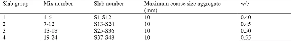
[image:4.595.38.530.459.529.2]An extensive research programme was carried out in order to measure and characterise the surface roughness of concrete surfaces prior to patch repairs in a much more accurate and reliable way and at the same time prove the ability of RRH to produce much rougher surfaces. Forty eight concrete slab specimens designated S1-S48 and with dimensions of 400 x400 x125 mm were produced in four groups. Each group had a different w/c ratio and consisted of twelve slabs cast in six different mixes. In total twenty-four mixes were produced. Two slabs and six 100 mm cubes were produced from each mix. The w/c ratios of groups 1, 2, 3 and 4 were 0.4, 0.45, 0.50 and 0.55 respectively. Details of all slab mixes are shown in Table 1.
Table 1 Details of slab mixes.
Slab group Mix number Slab number Maximum coarse size aggregate
(mm)
w/c
1 1-6 S1-S12 10 0.40
2 7-12 S13-S24 10 0.45
3 13-18 S25-S36 10 0.50
4 19-24 S37-S48 10 0.55
Materials
The specimens were produced using OPC CEM I 42.5 N (BS EN 197-1, 2000). Coarse sharp sand (50% passing a 600 m sieve) was used as fine aggregate. Uncrushed river gravel with maximum coarse size of 10 mm was used as coarse aggregate. The mix design of the specimens was based on the guidelines of BRE (Design of normal concrete mixes, 1998).
Casting and curing of slab specimens
The specimens were cast in timber moulds and compacted using a vibrating table. After the concrete had set, the moulds were covered with damp rags. Twenty-four hours after casting the specimens were de-moulded and placed in water. After six days in water, the specimens were air-cured in a storage room for 21 days. The storage room temperature was 19 oC at 50 to 60% relative humidity.
Surface preparation
P5) that were previously subjected to RRH were also used for comparison purposes. A panoramic view of all specimens is shown in Fig. 1.
Fig. 1 Concrete substrate surfaces obtained using either RRH or an electric hammer.
SELECTION OF ROUGHNESS PARAMETERS
The first step in measuring and characterising concrete substrate surfaces is the acquisition of a satisfactory profile. Once an adequate profile is obtained, it should be analysed and characterised using some form of roughness index or parameter. Unfortunately there is no universal number, descriptor or parameter that can be used to analyse and characterise the topography of a surface. A large number of two-dimensional (2D) and three-dimensional (3D) roughness parameters have been developed to characterise the roughness of a surface for various processes and applications in various sciences and fields of engineering. A review of the various 2D parameters is provided by (Gadelmawla et al, 2002), whereas a detailed review of both 2D and 3D parameters is provided by (Griffiths, 2001) and (Bewoor & Kulkarni, 2009).
In the field of concrete patch repairs, the bond strength is considerably influenced by the topography (roughness) of the substrate surface obtained after removal of the defective concrete. Hence, roughness parameters sensitive to changes which influence the amount of surface contact area available between concrete substrates and repair materials should be chosen and evaluated. Based on the above criterion, 2D roughness parameters which seem to be important for mechanical interlocking (Maerz et al, 2001); (Griffiths, 2001); (Gadelmawla et al, 2002)and (Bewoor & Kulkarni, 2009) are given in eqs. (1) to (6) below:
Parameter 1: Average absolute slope Ra
𝑹𝐚 = 𝟏𝑳∫ |𝟎𝑳 𝒅𝒛𝒅𝒙| 𝒅𝒙 (1)
or in discretised form
𝑹𝐚 = 𝟏𝑳∑𝑵𝒏=𝟏|𝒛𝒏+𝟏− 𝒛𝒏| (2)
Parameter 2: Root mean square average slope Rq
𝑹𝒒 = √𝟏𝑳∫ (𝟎𝑳 𝒅𝒛𝒅𝒙)𝟐𝒅𝒙 (3)
or in discretised form
Parameter 3: Profile length ratio Lr
𝑳𝒓 =𝑳𝒐𝑳 =𝟏𝑳∫ √𝟏 + (𝟎𝑳 𝒅𝒙𝒅𝒛)𝟐𝒅𝒙 (5)
or in discretised form
𝑳𝒓 =𝑳𝒐𝑳 =𝟏𝑳∑𝑵 √(𝑵𝑳)𝟐+ (𝒛𝒏+𝟏− 𝒛𝒏)𝟐
𝒏=𝟏 (6)
where, Ra is the average absolute slope (rad); Rq is the root mean square average slope (rad); Lr is the profile length ratio; dz/dx is the local slope of the surface profile; Lo is the actual profile length (mm); L
is the evaluation length along the x axis (mm).
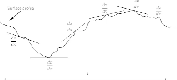
Ra is evaluated by first calculating the slope between each two successive points of the surface profile as shown in Fig. 2. Next, the average of these slopes is evaluated. When it comes to Rq, the root mean square of the average slope is calculated instead. Both Ra and Rq parameters are important for properties such as mechanical interlocking. A surface with high Ra and Rq values can provide better mechanical interlocking compared to a surface with low Ra and Rq values. Lr parameter is given as the ratio of the actual profile length Lo over the evaluation length L and is also important when it comes to mechanical interlocking. A surface with high peaks and deep valleys would have a higher Lo and hence
Lr value compared to a surface with low peaks and shallow valleys. Thus more surface area is available for the repair material to adhere.
Fig. 2Local slopes along the surface profile.
SURFACE ROUGHNESS MEASURING EQUIPMENT
An experimental 3D interferometric fringe-based imaging system for surface profiling, positioning and control for space applications developed by (Meggitt et al, 2002) was used to characterise the substrate surfaces. The method belongs to a group of non-contact (optical) techniques known as phase measurement interferometry.
The measuring system consists of a fringe projector, a camera, a control system for the laser diode and a computer for processing the data. The fringe projector illuminates the surface of the object under investigation with a set of vertical interference fringes through an illumination cone as shown in Fig. 3. Projected fringes having cosine intensity profiles are used. The pattern of the projected fringes on the surface of an object can then be analysed to find the co-ordinates of points on the surface. The aim of using projected fringes, instead of a scanning spot or line, is that data for all points in an image plane can be captured simultaneously, hence reducing the image acquisition time. The fringe projector, object and camera remain stationary during measurement (Meggitt et al, 2002).
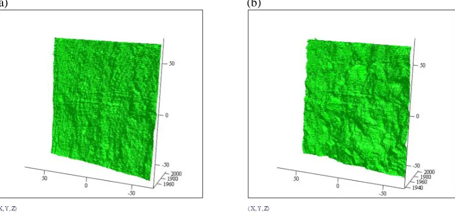
[image:6.595.42.337.375.509.2]images and performing all necessary calculations to produce the x, y and z co-ordinates of the surface points (Meggitt et al, 2002). By using the above described equipment it is possible to capture and analyse a square area of approximately 140 x 140 mm on the x-y plane. Both x and y axes are divided into 251 points, resulting in a spacing length of approximately 0.5 mm and in a very fine square mesh consisting of 251 lines on both x and y axes and a total of 63001 points. Next, the z-coordinates of the 63001 points are generated and stored in a matrix form. Once the image is captured and analysed a very detailed and accurate 3D topography of the surface is created using Mathcad software as shown in Fig. 4. This is one of the big advantages of the above system when compared to sand patch method and contact stylus profilometers. Finally, the z axis coordinates of the 63001 points can be processed using computer software such as Mathcad or Matlab to calculate various 2D roughness parameters on either x or y axis. The 2D parameters Ra, Rq and Lrdescribed above were used to measure the surface roughness of the substrate samples. For this purpose, computer programmes for evaluating each one of them along the x
axis of the specimens were written in Matlab.
Fig. 3 Schematic diagram of fringe-based laser interferometry equipment used to measure surface roughness of the concrete substrates.
(a) (b)
Fig. 4Typical 3D surfaces obtained using (a) an electric hammer and (b) Remote Robotic Hydro-erosion.
RESULTS AND DISCUSSION
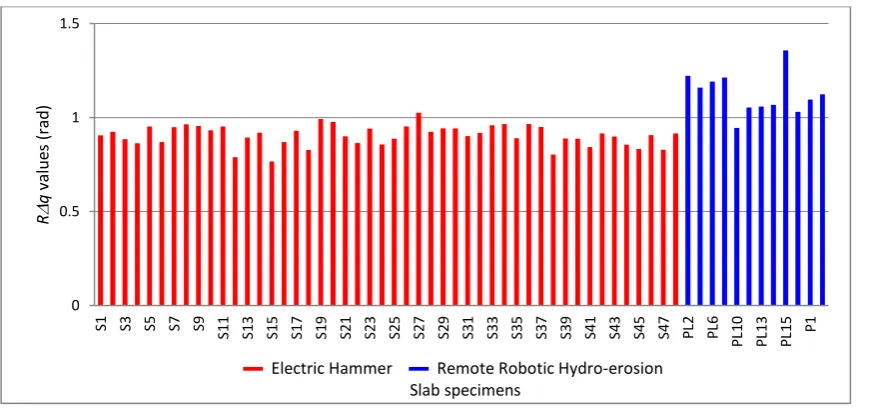
[image:7.595.51.399.268.406.2] [image:7.595.48.492.467.679.2]every mesh line parallel to the x axis and an average roughness value based on the results of 251 such lines was obtained for each slab. The measured values of all concrete substrate slab surfaces (produced using either an electric hammer or RRH) are shown in Figs. 5-7, whereas a summary of all the above results is provided in Table 2. As shown in Table 2, all three 2D roughness parameters were able to distinguish between surfaces obtained by the two removal methods and confirm that RRH produces rougher surfaces which can promote bond strength. When Ra parameter was employed, RRH showed an average increase in surface roughness of 29% along the x axis. RRH resulted in an average increase of 24% along the x axis when Rq parameter was used. Finally, when Lr was considered, RRH yielded an average increase in surface roughness of 10% along the x axis.
[image:8.595.42.477.194.396.2]Fig. 5Ra values (rad) measured along the x axis.
Fig. 6 Rq values (rad) measured along the x axis.
0 0.5 1 1.5
S1 S3 S5 S7 S9 S11 S13 S15 S17 S19 S21 S23 S25 S27 S29 S31 S33 S35 S37 S39 S41 S43 S45 S47 PL2 PL6
P
L1
0
P
L1
3
P
L1
5 P1
R
a
valu
es
(
rad
)
▬ Electric Hammer ▬ Remote Robotic Hydro-erosion Slab specimens
0 0.5 1 1.5
S1 S3 S5 S7 S9 S11 S13 S15 S17 S19 S21 S23 S25 S27 S29 S31 S33 S35 S37 S39 S41 S43 S45 S47 PL2 PL6
P
L1
0
P
L1
3
P
L1
5 P1
R
q
valu
es
(
rad
)
[image:8.595.42.478.435.639.2]Fig. 7Lr values measured along the x axis.
Table 2 Ra, Rq and Lr roughness parameters range of measured values.
Roughness parameter
Range of measured values Mean values Percentage increase
by using RRH (%) Electric hammer
prepared surfaces
RRH prepared surfaces
Electric hammer prepared surfaces
RRH prepared surfaces
Ra (rad) 0.79-1.03 0.97-1.28 1.20 1.29 29
Rq (rad) 0.77-1.03 0.95-1.36 0.91 1.13 24
Lr (-) 1.36-1.54 1.49-1.73 1.46 1.61 10
CONCLUSIONS
The following conclusions can be drawn from the present experimental investigation of measuring concrete substrate surface roughness prior to patch repair:
Remote Robotic Hydro-erosion (RRH) which is a controlled version of hydro-demolition can be used to successfully remove defective concrete at a uniform depth and with good edge definition prior to patch repairs.
A non-contact fringe-based laser interferometry imaging technique suitable for on-site application can be used to create a very accurate 3D digital profile of a concrete substrate surface regardless of its orientation (horizontal, vertical or overhead).
2D roughness parameters Ra, Rq and Lr can be successfully employed to measure the substrate surface roughness. They confirm the ability of Remote Robotic Hydro-erosion to produce significantly rougher surfaces than pneumatic chipping hammers and hence improve mechanical interlocking, which in turn promotes bond strength.
Finally, it should be noted that the above prototype roughness equipment has the potential for future use in other fields of concrete repair and protection, where surface roughness is important such as installation of FRP strengthening laminates or water proof coatings.
ACKNOWLEDGEMENTS
The author is deeply grateful to Professor D. Chamberlain for his guidance and support in conducting the above research. Special thanks go to Professor B. T. Meggitt, Dr W. Boyle and J. Couper for providing the fringe-based laser interferometry equipment and assisting with the measurements. Finally, the author would like to express his gratitude to Professor P. Mangat for his valuable comments and suggestions regarding completion of the above work.
0 0.3 0.6 0.9 1.2 1.5 1.8
S1 S3 S5 S7 S9 S11 S13 S15 S17 S19 S21 S23 S25 S27 S29 S31 S33 S35 S37 S39 S41 S43 S45 S47 PL2 PL6
P
L1
0
P
L1
3
P
L1
5 P1
Lr
valu
es
[image:9.595.38.534.326.400.2]REFERENCES
Abu-Tair, A.I., Lavery, D., Nadjay, A., Rigden, S.R. and Ahmed T.M.A. (2000), A new method for evaluating the surface roughness of concrete cut for repair or strengthening, Constr Build Mater, Vol. 14, 171-6.
Bewoor, A.K. and Kulkarni, V. A. (2009), Metrology and measurement, 1st ed, New Delhi, McGraw-Hill.
BS EN 197-1 (2000), Cement-Part 1: Composition, specifications and conformity criteria for common cements. London, UK), British Standards Institution.
BS EN 1504-10 (2003), Products and systems for the protection and repair of concrete structures-Definitions-Requirements-Quality control and evaluation of conformity-Part 10: Site application of products and systems and quality control of the works. London, UK, British Standards Institution.
BS EN 1766 (2000), Products and systems for the protection and repair of concrete structures-Test methods-Reference concretes for testing. London, UK), British Standards Institution.
BS EN ISO 3274 (1998), Geometric Product Specifications (GPS)-Surface Texture: Profile method-Nominal characteristics of contact (stylus) instruments. London, UK, British Standards Institution.
BS EN ISO 4288 (1998), Geometric Product Specification (GPS)-Surface texture-Profile method: Rules and procedures for the assessment of surface texture. London, UK, British Standards Institution.
Chamberlain, D. A. (2003), A robotics approach to preparing surfaces for repair. Concr, Vol. 37, 22-23.
Chamberlain, D., Gambao, E., McCormac, S., Garcia, M. A., McCulloch, T., Alves Seibert, C. A. et al. (1999), HEROIC: A concept robotic system for hydro-erosion in concrete repair preparation. In: Proceedings of the 16th International Symposium on Automation and Robotics in Construction, Spain.
Dellate, Jr N. J., Fowler, D. W., McCullough, B. F. and Grater, S. F. (1998), Investigating performance of bonded concrete overlays. J Perform Constr Facil, Vol. 12, 62-70.
Design of normal concrete mixes (1998), 2nd ed. Garston: Building Research Establishment.
Gadelmawla, E. S., Koura, M. M., Maksoud, T. M. A., Elewa, I. M. and Soliman, H. H. (2002), Roughness parameters, J Mat Process Technol, Vol 123, 133-145.
Griffiths, B. (2001), Manufacturing surface technology, 1st ed. London, Penton Press.
Hindo, K. R. (1990), In-plane bond testing and surface preparation of concrete, Concr Int, Vol. 12, 46-48.
ICRI Technical guideline No. 03732 (1997), Selecting and specifying concrete surface preparation for sealers, coating and polymer overlays, International Concrete Repair Institute, Rosemont, Illinois, USA.
Maertz, N. H., Nanni, A., Mayers, J.J. and Galecki, G. (2001), Laser profilometry for concrete substrate characterization prior to FRP laminate application, Concr Repair Bull, Vol. 1, 4-8.
Meggitt, B. T. et al (2002), A new self-calibrating 3D interferometric fringe-based imaging system for profiling, positioning and control in space use. European Space Agency Final Report 15787/02/NL/PA.
Mindess, S., Young, J. F. and Darwin D. (2003), Concrete. 2nd ed. Upper Saddle River, Prentice Hall.
Neville, A. M. (2011), Properties of concrete. 5th ed. Harlow, Essex: Pearson Education Limited.
Silfwerbrand J. (1986), Bonding between old and new concrete in structures loaded by static and time-dependent load. In: Proceedings of the International Conference on Adhesion Between Polymers and Concrete. France.