resonance for efficient wireless power transfer
ROZMAN, Matjaz, FERNANDO, Michael, ADEBISI, Bamidele, RABIE, Khaled
M, KHAREL, Rupak, IKPEHAI, Augustine and GACANIN, Haris
Available from Sheffield Hallam University Research Archive (SHURA) at:
http://shura.shu.ac.uk/23883/
This document is the author deposited version. You are advised to consult the
publisher's version if you wish to cite from it.
Published version
ROZMAN, Matjaz, FERNANDO, Michael, ADEBISI, Bamidele, RABIE, Khaled M,
KHAREL, Rupak, IKPEHAI, Augustine and GACANIN, Haris (2017). Combined
conformal strongly-coupled magnetic resonance for efficient wireless power transfer.
Energies, 10 (4), p. 498.
Copyright and re-use policy
See
http://shura.shu.ac.uk/information.html
Article
Combined Conformal Strongly-Coupled Magnetic
Resonance for Efficient Wireless Power Transfer
Matjaz Rozman1, Michael Fernando1, Bamidele Adebisi1,*, Khaled M. Rabie1, Rupak Kharel1, Augustine Ikpehai1and Haris Gacanin2
1 School of Engineering, Manchester Metropolitan University, Manchester M1 5GD, UK;
matjaz.rozman@stu.mmu.ac.uk (M.R.); m.fernando@mmu.ac.uk (M.F.); k.rabie@mmu.ac.uk (K.M.R.); r.kharel@mmu.ac.uk (R.K.); augustine.ikpehai@stu.mmu.ac.uk (A.I.)
2 Nokia Bell Labs Copernicuslaan 50, 2018 Antwerp, Belgium; haris.gacanin@nokia-bell-labs.com
* Correspondence: b.adebisi@mmu.ac.uk; Tel.: +44-7985-399-832
Academic Editor: Hongjian Sun
Received: 7 December 2016; Accepted: 4 April 2017; Published: 7 April 2017
Abstract: This paper proposes a hybrid circuit between a conformal strongly-coupled magnetic resonance (CSCMR) and a strongly-coupled magnetic resonance (SCMR), for better wireless power transmission (WPT). This combination promises to enhance the flexibility of the proposed four-loop WPT system. The maximum efficiency at various distances is achieved by combining coupling-matching between the source and transmitting coils along with the coupling factor between the transmitting and receiving coils. Furthermore, the distance between transmitting and receiving coils is investigated along with the distance relationship between the source loop and transmission coil, in order to achieve the maximum efficiency of the proposed hybrid WPT system. The results indicate that the proposed approach can be effectively employed at distances comparatively smaller than the maximum distance without frequency matching. The achievable efficiency can be as high as 84% for the whole working range of the transmitter. In addition, the proposed hybrid system allows more spatial freedom compared to existing chargers.
Keywords:conformal strongly-coupled magnetic resonance (CSCMR); strongly-coupled magnetic resonance (SCMR); efficiency; flexibility; matching; wireless power transfer (WPT)
1. Introduction
Wireless power transfer (WPT) technology is capable of charging electronic devices wirelessly eliminating the traditional cable requirement. This technology is not only more convenient, but can also enhance the health and safety within both domestic and commercial environments. Although WPT can be realized using either inductive coupling or radio frequency (RF) signals (see e.g., [1–3]), the former will be the focus of this paper.
Recently, a great number of attempts have been made towards the deployment of inductive WPT systems, since low energy density batteries are no longer sufficient to saturate the escalating energy demand of the electronic apparatus [3,4]. The need for an industry standard for the interoperability of the wireless devices was elevated simultaneously with the increasing number of wireless charging efforts. As a result, the Qi standard was introduced by the wireless power consortium and was adopted for both low and medium wireless power charging specifications during the last few years [5–7]. This standard is based on a tightly coupled two-coil system supporting charging up to 5 W. However, the efficiency of the two-coil system fluctuates upon the coil alignment and the distance between the transmitting coil (Tx) and receiving coil (Rx) [8,9]. The two-coil charging system has also been proposed for numerous appliances, especially for electric vehicle (EV) charging applications [10,11].
In order to maximize the distance between the Tx and Rx, the strongly-coupled magnetic resonance (SCMR) method was introduced in 2007 [12]. The Authors of this study pointed out that this method is capable of wirelessly transferring 60 W of electrical power over a distance of 2 m with 40% efficiency. Moreover, the SCMR system has demonstrated higher efficiencies by designing the transmitting and receiving resonant loops to resonate at the same frequency, where they exhibit the maximum quality factor [13]. However, the fact that the SCMR system has a high sensitivity to the misalignment between the coils [14,15] and its bulky structure are two main drawbacks of this system. In order to overcome these drawbacks, the conformal SCMR (CSCMR) concept was introduced in [16]. In this method, both the transmitter and receiver are embedded in the same plane with Tx and Rx resonators. A few novel designs of the CSCMR system are also built on the printable version; see, e.g., [17–19].
Critically coupled resonators are required in order to achieve maximum efficiency of SCMR systems [20,21]. Thus, the resonant frequency of the Tx and Rx loop varies due to the air gap between resonators. The impedance matching technique was implemented in [22,23], while [24] recites the adaptive matching method implemented to maintain the maximum level of system efficiency. Furthermore, in [25], a transmission coil array technique was proposed where appropriate phase weights of the transmission circuit are used according to the energy deposition profile of the receiving coil. However, in previous research studies, it is assumed that the coupling coefficient between source and Tx loop is fixed; therefore, the system performance was analysed upon multiple distances between Tx and Rx loops.
Misalignment and angle alignment also play a crucial role in the efficiency of WPT systems. For instance, the authors in [26–28] explored the impact of the misalignment and angle alignment on the two coils, which are magnetically coupled in a resonant wireless power system. In addition, this study proposed algorithms capable of adjusting the transmitting frequency to achieve maximum efficiency. Moreover combining the two systems will simultaneously reduce the bulkiness of the receiver coils while enhancing the spatial freedom at the transmitting end.
In this paper, we explore the possibility of maintaining the maximum efficiency of four loop inductive coupling method at any distance between the Tx and Rx loops by either reducing or increasing the gap between the source and Tx loops. To the best of our knowledge, no existing work has considered this in the open literature. This will allow more spatial freedom in terms of receiver positioning without using frequency matching algorithms, since the system frequency remains constant. This may also reduce the cost of the power source, since it can be designed to operate at a single frequency. Therefore, the contributions of this paper are as follows. We first derive an analytical model of combined SCMR-CSCMR system, which simultaneously enhances the flexibility and usability of both models. Additionally, the relationship between the source and Tx loop gap is studied, in relation to the gap between the Tx and Rx resonating loops along with the effect of the loop dimensions. The second contribution of this work resides in conducting an experiment to validate the analytical results. Furthermore, a novel concept for flexible charging will be introduced where the receiver position can be adjusted to enhance the maximum efficiency without using multiple coils or adjusting the frequency. Results demonstrate that the proposed system is able to attain higher efficiencies compared to frequency matching, being further close to the maximum. This further indicates that the system performance was least affected by the combined SCMR-CSCMR method or by the adjustments to the distance between the source loop and Tx.
2. System Model of the Proposed Hybrid WPT System
The hybrid WPT model proposed in this study is shown in Figure 1. This system merges two different wireless transmission system concepts. The transmitting end is designed using the SCMR concept, where the source loop is placed outside the Tx loop in order to provide the flexibility of changing distance between the two loops. On the other hand, the receiver implementation is based on the CSCMR concept, where the load loop is placed concentrically inside the Rx loop. This concept significantly shrinks the size of the receiver end while the coupling between the two coils remains fixed.
Source
Tx
Rx
Load
d12
d23
k12
k23
k34
r
r
r
r
1 2
3
[image:4.595.141.454.200.434.2]4
Figure 1.Combined SCMR-CSCMR system.
For instance, when the distance between Tx and Rx (d23) is changed, the coupling factor (k23)
varies accordingly. In order to compensate the corresponding change to maximize the system efficiency, the coupling factor (k12) must be simultaneously altered. According to the CSCMR concept,
the coupling factor (k34) remains fixed; hence, only the coupling factork12can be changed by adjusting
the distance between the source and Tx loops (d12). Therefore, a relationship between the two distances 4d
23 4d12
has to be expressed.
3. Theoretical Analysis of Strongly-Coupled WPT Systems
AC
Rs
R2 R4
RL
C2 C3
L1 L2 L3 L4
R1 R3
I
I
I
I
1
2
3
4
M
M
[image:5.595.140.453.85.213.2]M
12
23
34
Figure 2.Equivalent hybrid SCMR and CSCMR circuit diagrams.
The electromagnetic induction field (H) for one of the parallel coaxial loops can, as follows based on Ampere’s law and Faraday’s electromagnetic induction law [31,32], be shown as:
Hy=
Z
4Hy=
Ixr2y
2r2
y+d2
32 (1)
wheredrepresents the distance between the two loops,ryrepresents the radius ofy-th loop andIxis the
current through thex-th loop. It is worth noting that Equation (1) is more accurate at short distances. However, in order to simplify the analysis in this study, we approximate the mutual inductance (M) between thex-th andy-th loops including the area enclosed by the coil [33,34], as:
Mxy=
µ0HyAy
Ix
= µ0r
2
xr2yπ
2
r
r2
y+d2
3
(2)
where rx andry represent the radius of the x-th and y-th loops, respectively andµ0 donates the
permeability of free space. Ay stands in for the area of they-th loop and can be mathematically
expressed asAy=πr2y.
For the Rx elements of the CSCMR system, which consist of two coaxial loops placed concentrically on the same plane, the magnetic field is usually attributed to the larger loop. Therefore, when the distanced34= 0, the mutual inductance can be simplified as:
Mxy=
µ0r2xπ
2ry (3)
whererxry. A coupling coefficient between the two loops can be expressed as:
kxy=
Mxy
√ LxLY
. (4)
The current in each circuit can be calculated by applying Kirchoff’s voltage law. Therefore, the scattering parameterS21, which represents the ratio between the signal at the output port and the
injected signal at the input, can be calculated as:
S21 =2VL
VS
RS
RL
12
. (5)
Combined with Equation (4), theS21parameter can be given as:
S21 =
A
where:
A=j2ω3k12k23k34L2L3 p
L1L4RsRL
B=Z1Z2Z3Z4
C=k212L1L2Z3Z4ω2
D=k223L2L3Z1Z4ω2
E=k234L3L4Z1Z2ω2
F=k212k234L1L2L3L4ω4
(7)
andZ1,Z2,Z3andZ4are the loop impedances of the four coils and can be calculated as:
Zx=Rx+jωLx−j 1
ωCx (8)
whereRx,LxandCxrepresent total resistance, the equivalent inductance and external capacitance of
thex-th loop, respectively.
In order for the system to function at its maximum efficiency, the resonant frequency can be calculated as:
η= PLOAD
PSOURCE
= |S21| 2
1− |S11|2
(9)
For the system to work at maximum efficiency, resonant frequency (f0) is calculated as:
f0= 1
2πp(LC)
(10)
It is also important that theQof the Tx and the Rx loops be high [30]. TheQof they-th loop can be expressed as:
Qy=
ω0Ly
Ry (11)
whereω0denotes the angular frequency, which can be calculated asω0 = ωy = √L1
yCy in terms
ofhrads i.
4. Numerical Analysis
The efficiency of both the CSCMR and SCMR systems strongly depend on the geometrical parameters of the loops. The above system has been designed to have its maximum operating distance of 12 mm when it operates at a frequency of 7.2 MHz. The radius of the source loop, Tx loop and Rx loop,(r1=r2=r3), was calculated from Equations (2) and (3) and set at 30 mm. As calculated in [35],
the system will achieve the maximum distance when the coupling factor between Rx and load loops
(k34)is equal to 0.1. To ensure that the coupling factork34 matches the requirements, the radius of
the load loop(r4)was calculated as 5 mm, and its inductance was set asL4=0.19µH. In addition,
to ensure that the Q requirement between the two loops is fulfilled, the inductance of Rx is set to
L3=0.739µH. From Equation (9), the capacitance of the Rx loop can be calculated asC3=661.2 pF,
so that the required loop resonating frequency is achieved.
The inductance of the Tx loop(L2)was set at 2.402µH to ensure that the coupling factor and
quality factor requirements are met. The desired capacitance of the Tx loop was calculated from Equation (9) and set atC2=203.42 pF to ensure that the requirements for resonant frequency are met.
when the load power split from a single peak to a double peak. The phenomenon is an increasing coupling factor between the Rx and Tx loops when the distance between them(d23)decreases to a
[image:7.595.184.412.165.229.2]critical point.
Table 1.Calculated values of the loops elements.
RS;RL= 50 r1=r2=r3= 30 mm r4= 5 mm R1= 0.015Ω C1= 525.97 pF L1= 0.929µH
R2= 0.03Ω C2= 203.42 pF L2= 2.402µH R3= 0.02Ω C3= 661.2 pF L3= 0.739µH R4= 0.012Ω C4= 2571.1 pF L4= 0.19µH
Our analytical model was used to study the impact on the system efficiency due to the alternations of the distancesd23andd12on the efficiency of the system. In addition, it was reviewed how the impact
can be used to maintain the maximum efficiency at various distances between Tx and Rx without altering the transmitting frequency.
Frequency (MHz)
7.05 7.1 7.15 7.2 7.25 7.3 7.35
[image:7.595.177.416.311.501.2]Efficiency (%) 0 10 20 30 40 50 60 70 80 90 100 dis.7mm dis.9mm dis.12mm dis.15mm
Figure 3.Maximum distance and frequency splitting phenomenon of the calculated system.
From Figure3, it is also evident that the maximum efficiency appears when the distance between Tx and Rx loops is equal to 12 mm, and therefore, the coupling factor between them can be calculated ask23 =0.0045, using Equations (2) and (4). The coupling factor between the source loop and Tx is
equal to 0.1. From the two known coupling factors, the relationship between distancesd12andd23can
be calculated from Equations (2)–(4) as:
k12
k23 =
µ0r12r22π 2
q
(r2 2+d12)
3 !
√ L2L3
µ0r22r33π 2
q
(r2 3+d23)
3 !
√ L1L2
(12)
After substituting all of the known variables into Equation (12), the relationship between the distancesd12andd23can be derived as:
d12 =
0.355689r2d23L
(16)
3
The relationship between the distances in Equation (13) is simulated in MATLAB, and the obtained results are presented in Figure4. It is evident that with the right calculation of the relationship between
d12andd23, the maximum power transmission of the SCMR system can be also achieved at comparably
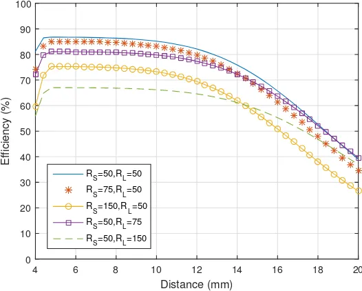
shorter distances than the system’s maximum range. Eminently, the transmission frequency remains unaffected within the whole transmission range, which eliminates the necessity of matching circuits and tuning capacitors [36]. Figure5represents the maximum efficiency of the system if different load and source resistances are applied. While the resistance of the source does not have a big impact on maximum efficiency, the impact of increasing load resistance is more significant. In order to improve the performance, where the impedance of the source loop does not match the impedance of the load loop, various impedance matching techniques can be used [37,38]. However, the matching algorithms are not compulsory in this study since this experiment was carried out using a signal generator and spectrum analyser with the source and the load having 50Ωinput impedances.
Frequency (MHz)
7.05 7.1 7.15 7.2 7.25 7.3 7.35
Efficiency (%)
0 10 20 30 40 50 60 70 80 90 100
[image:8.595.167.427.260.470.2]dis.7mm dis.9mm dis.12mm dis.15mm
Figure 4.Simulated efficiency of the hybrid system using the calculated equation for the distance(d12).
Distance (mm)
4 6 8 10 12 14 16 18 20
Efficiency (%)
0 10 20 30 40 50 60 70 80 90 100
R
S=50,RL=50
RS=75,RL=50
RS=150,RL=50
RS=50,RL=75
R
S=50,RL=150
[image:8.595.165.428.508.719.2]5. Experimental Setup
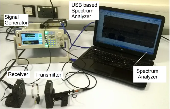
[image:9.595.131.464.188.402.2]In this section, an experimental setup is presented and is then utilized to explore the impact of various system parameters on the performance. In order to verify the calculated results, an appropriate system was built to comply with the calculations’ model. The two loops forming the transmitter have the same size forming the SCMR system design, and the other two loops are embedded, forming the CSCMR design receiver, as shown in Figure6.
Figure 6.Practical implementation of the combined CSMR-SCSMR approach.
5.1. System Design and Measurement
The transmitter consists of the source and TX loops. The source loop is made of a 2.3-turn, silver-plated copper wire, while the Tx loop is made of the same wire and contains 5 turns. The receiver side of the system is made using the same wire where the Rx loop contains 1.6 turns, and the load loop is made of 1.2 turns of the wire. Ceramic capacitors were used to tune the loops to the same oscillating frequencies.
For measurement purposes, a signal generator was used to send various frequencies to the source loop, while the response was measured using a USB base spectrum analyser. Finally, the measured results were displayed using computer-based software communicating with the spectrum analyser.
5.2. System Maximum Efficiency
According to the calculation, an optimal design appears when the distanced12is equal to 3.4 mm.
In this scenario, the maximum efficiency can be achieved when the distanced23 is equal to 12 mm.
The graphical representation in Figure7is plotted using the measurements and exhibits the maximum efficiency at a distance equal to 11.8 mm. The maximum efficiency of the obtained experimental setup is 79%, which is comparable, to some extent, to the 84% efficiency calculated in Section2. The difference can be attributed to the displacement, the shapes of the coils and variation in the electronic components. The instrument used during the testing process can also have effects on the experiment.
Frequency (MHz)
7.05 7.1 7.15 7.2 7.25 7.3 7.35 7.4
Efficiency (%)
0 10 20 30 40 50 60 70 80 90
[image:10.595.166.428.86.301.2]dis.7mm dis.9mm dis.12mm dis.15mm
Figure 7.MATLAB converted results in transmission efficiency (%).
Frequency (MHz)
7 7.05 7.1 7.15 7.2 7.25 7.3 7.35 7.4 7.45 7.5
Efficiency (%)
0 10 20 30 40 50 60 70 80 90 100
Measured efficiency Calculated Efficiency
Figure 8.Frequency misalignment between the mathematical model at 7.2 MHz and the experimental setup at 7.22 MHz.
5.3. Combined System Efficiency
In order to achieve the maximum efficiency, the distance between the source loop (S) and Tx has to be adjusted according to the distance between the Tx and Rx loops as calculated in Equation (12). As presented in Figure9, the displacement∆d23between the Tx and Rx loops was compensated by
adjusting the distance between S and Tx for∆d12in order to achieve the maximum efficiency. The RX
loop in Figure9represents the receiver loop (Tx) with the embedded load loop, andd23maxrepresents
[image:10.595.165.429.338.549.2]Rx
Rx’
TX
S
S’
__ d23
d
23max__d12
d12max
[image:11.595.129.466.85.313.2]Receiver
Transmitter
Figure 9.Maximum efficiency measurements setup.
Frequency (MHz)
7 7.05 7.1 7.15 7.2 7.25 7.3 7.35 7.4 7.45 7.5
Efficiency (%)
0 10 20 30 40 50 60 70 80 90
dis.7mm dis.9mm dis.12mm dis.15mm
Figure 10.Measured combined SCMR-CSCMR system the holding maximum efficiency at a frequency of 7.23 MHz.
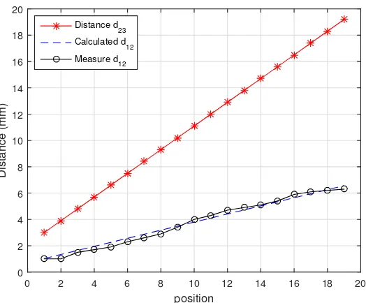
In order to justify the calculated results, the maximum distance d12 was measured at the
point where the system demonstrated its maximum efficiency along with the random distanced23.
[image:11.595.161.434.346.567.2]Table 2.Comparison between the measured and calculated distances (d12) and variation between the two in %.
d23(mm) Calculatedd12(mm) Measuredd12(mm) Variation (%)
3 1 1 0
4 1.3 1 23
5 1.6 1.5 6.2
6 1.9 1.8 5.2
7 2.2 2 10
8 2.5 2.3 8
9 2.8 2.6 7.1
10 3.1 2.9 6.4
11 3.4 3.2 5.8
12 3.7 3.6 2.7
13 4 4.1 0.4
14 4.3 4.5 4.6
15 4.6 4.9 6.5
16 4.9 5 2
17 5.2 5.3 1.9
18 5.5 5.6 1.8
19 5.8 5.9 1.7
20 6.1 6.1 0
21 6.4 6.1 4.6
Figure11shows a graphical presentation of a comparison between the random distanced23and
the measured value ofd12against the calculated value,d12.
position
0 2 4 6 8 10 12 14 16 18 20
Distance (mm)
0 2 4 6 8 10 12 14 16 18 20
Distance d23 Calculated d
12
Measure d
[image:12.595.167.429.405.622.2]12
Figure 11.The relation between the distancesd12andd23and a measured distanced12.
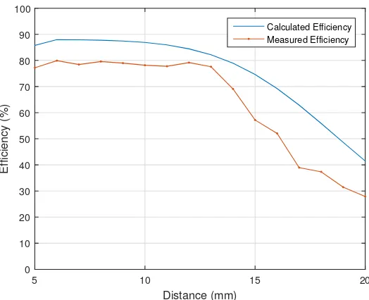
The efficiency of the system was measured, combining the pre-measured and calculated data to achieve maximum efficiency. In Figure12, the measured efficiency is compared to the calculated one of the system for multiple random distances, which fits well with the calculated pattern ofd12
Distance (mm)
5 10 15 20
Efficiency (%)
0 10 20 30 40 50 60 70 80 90 100
[image:13.595.166.428.85.298.2]Calculated Efficiency Measured Efficiency
Figure 12.Comparison between the calculated and measured efficiencies of the system.
5.4. Angle Coverage
The position angle of the transmitter and receiver is also another crucial factor that may impact the system efficiency. In order to measure the efficiency, the angle of the receiver was constantly changed according to the angle of the transmitter, which varied between 0◦and 90◦, as illustrated in Figure13. The position of the receiver was also placed at various distances according to the transmitter. For instance, as shown in Figure9,∆d23indicates the change of the distance between the RX’ to the
previous RX position, which is 1 mm. d23maxindicates the distance between the final RX position and
the Tx, which is 20 mm for our measurements.
TX S S’
Transmitter
Rx Rx’
Receiver
d23
R
x
R
x
’
R
e
ce
iv
e
r
d
2
3
d23max
d23
[image:13.595.135.464.458.734.2]d12
Simultaneously, the distance between the Tx and S was adjusted(∆d12)according to the changes
made, distance-wise between the Tx and the RX(∆d23); see Figure13. This further indicates the
changes made to distanced12to achieve the highest efficiency according to the previous measurements.
The receiver placement was changed for 30◦ according to the previous measurements, and the measurement was repeated for new alignment.
As Figure14indicates, the maximum efficiency drops in accordance with the angle at which the transmitter is being placed. The greater the angle between transmitter and receiver, the lower the efficiency of the charger is and vice versa. It can also be seen that the angle above 30% highly affects the charging efficiency, as well as the distance at which the charger operates. Furthermore, the angle above 60% reduces the working range of the charger to a few millimetres and drastically decreases the efficiency.
From the measurements, it is evident that for the charger to have high efficiency and the highest possible distance covered, the angle placement must be lower that 30%.
Distance (mm)
0 2 4 6 8 10 12 14 16 18 20
Efficiency (%)
0 10 20 30 40 50 60 70 80 90
angle 0o
angle 30o
angle 60o
[image:14.595.143.452.275.527.2]angle 90o
Figure 14.Measured angle efficiency of the combined system for various angles between transmitter and receiver.
5.5. The Impact of the Coils’ Misalignment
A misalignment between the transmitter and receiver coils also plays an important role of relevance to the system efficiency. As presented in Figure15, the measurements were carried out by changing the position of the coverage between the transmitter and receiver loops from 100% coverage down to 10%. The measurements were commissioned at 0%, 50%, 70% and 90% misplacement. The distance between Tx and RX was also altered by∆d23 =1 mm, up tod23max, which was equal to
20 mm. The distance between Tx and S was also altered accordingly by∆d12, in order to maximize the
system efficiency.
Rx
Rx’
TX
S
S’
Receiver’
Transmitter
Rx
Rx’
Receiver
100% 90% 80% 70% 60% 50% 40% 30% 20% 10% 0%
C
d23
d23
d12 d12
[image:15.595.132.462.83.431.2]d23max
Figure 15.Positioning of the receiver for the measurement of the misalignment efficiency.
6. Charger Efficiency Based on the Measured Results
Our proposed wireless power charger design is based on real-time measurements. The charger efficiency is highly sensitive to both coil misalignment and the change of angle between the transmitter and receiver. Moreover, the charger efficiency possesses an inverse relationship with the misalignment and the change of angle. As measured, the maximum distance between the transmitter and receiver where the wireless charger demonstrates its high efficiency is 12 mm with an angle of 20%. Based on the experimental results in Figure16, a 50% misalignment may cause approximately 15% of an efficiency drop. From the previous calculation, it can be shown that the starting distance between TX and Rx will be 5 mm.
The charger transmitter circuit adjusts the distance between the source and transmitter loops to fulfil the changing position requirements of the receiver. However, in order to perform the charging efficiently, the charger must be capable of adjusting the angle to reach the receiver, as shown in Figure17.
Distance (mm)
0 2 4 6 8 10 12 14 16 18 20
Efficiency (%)
0 10 20 30 40 50 60 70 80 90
[image:16.595.167.428.85.302.2]mispl. 0% mispl. 50% mispl. 70% mispl. 90%
Figure 16. Measured misalignment efficiency of the combined system for various positions of the receiver.
Transmitter
Receiver
X
-X +X
Figure 17.Diagram of the proposed WPT charger system.
[image:16.595.145.451.353.576.2]Distance (mm)
0 10 20 30 40 50 60
Efficiency (%)
0 10 20 30 40 50 60 70 80 90 100
[image:17.595.165.428.85.298.2]Proposed System Conv. 2 Loop System
Figure 18.The efficiency of the proposed charger based on misalignment from the centre.
7. Conclusions
A hybrid SCMR-CSCMR system has been proposed in this paper. Varying the distance between the Tx and Rx loops can adversely impact the efficiency of WPT systems. However, the paper further explains that exploiting the variable distance between the source and Tx loops can be adjusted to meet the power transfer requirements, eliminating further performance penalties. Therefore, the proposed system adopted an adjustable SCMR concept at the transmitter side and the CSCMR model at the receiver end. This effort also illustrates that adaptively changing the distance between the source and Tx loops simultaneously aids the circuit to maintain the maximum efficiency throughout the whole transmission range provided, while the transmitting frequency remains unchanged. Further, the validated results also prove that the proposed charger provides better flexibility for devices to be charged within a 50-mm radius from the centre of the charging platform at a relatively high efficiency. Finally, the measured and calculated results tend to have similar results despite some differences, which resulted from the approximations used in our analysis.
Acknowledgments: This research has been carried out within the “Smart In-Building Micro Grid for Energy Management” project funded by EPSRC (EP/M506758/1) and supported by Innovate UK (Innovate UK Project 101836).
Author Contributions: Matjaz Rozman and Bamidele Adebisi conceived and designed the experiments. Matjaz Rozman performed the experiments. Matjaz Rozman and Michael Fernando analysed the data. Bamidele Adebisi and Khaled M. Rabie contributed materials and analysis tools. Matjaz Rozman and Khaled M. Rabie and Michael Fernando and Rupak Kharel wrote the paper. Augustine Ikpehai and Haris Gacanin reviewed the manuscript.
Conflicts of Interest:The authors declare no conflict of interest.
References
1. Rabie, K.M.; Adebisi, B.; Rozman, M. Outage probability analysis of WPT systems with multiple-antenna access point. In Proceedings of the 2016 10th International Symposium on Communication Systems, Networks and Digital Signal Processing (CSNDSP), Prague, Czech Republic, 20–22 July 2016; pp. 1–5. 2. Rabie, K.M.; Adebisi, B.; Alouini, M.S. Wireless power transfer in cooperative DF relaying networks with
3. Moriwaki, Y.; Imura, T.; Hori, Y. Basic study on reduction of reflected power using DC/DC converters in wireless power transfer system via magnetic resonant coupling. In Proceedings of the IEEE International Telecommunications Energy Conference, Amsterdam, The Netherlands, 9–13 October 2011; pp. 1–5. 4. Li, Y.; Mai, R.; Lin, T.; Sun, H.; He, Z. A novel WPT system based on dual transmitters and dual receivers for
high power applications: Analysis, design and implementation. Energies2017,10, 174.
5. Li, Y.; Wang, Y.; Cheng, Y.; Li, X.; Xing, G. QiLoc: A Qi wireless charging based system for robust user-initiated indoor location services. In Proceedings of the IEEE International Conference on Sensing, Communication, and Networking, Seattle, WA, USA, 22–25 June 2015; pp. 480–488.
6. Liu, X. Qi standard wireless power transfer technology development toward spatial freedom.IEEE Circuits Syst. Mag.2015,15, 32–39.
7. Van Wageningen, D.; Staring, T. The QI wireless power standard. In Proceedings of the International Power Electronics and Motion Control Conference, Ohrid, Macedonia, 6–8 September 2010; pp. 15–32.
8. Haldi, R.; Schenk, K.; Nam, I.; Santi, E. Finite-element-simulation-assisted optimized design of an asymmetrical high-power inductive coupler with a large air gap for EV charging. In Proceedings of the IEEE Energy Conversion Congress and Exposition, Denver, CO, USA, 15–19 September 2013; pp. 3635–3642. 9. Wen, F.; Huang, X. Optimal magnetic field shielding method by metallic sheets in wireless power transfer
system. Energies2016,9, 733.
10. Haldi, R.; Schenk, K. A 3.5 kW wireless charger for electric vehicles with ultra high efficiency. In Proceedings of the IEEE Energy Conversion Congress and Exposition, Pittsburgh, PA, USA, 14–18 September 2014; pp. 668–674.
11. Chen, W.; Liu, C.; Lee, C.H.T.; Shan, Z. Cost-effectiveness comparison of coupler designs of wireless power transfer for electric vehicle dynamic charging. Energies2016,9, 906.
12. Kurs, A.; Karalis, A.; Moffatt, R.; Joannopoulos, J.D.; Fisher, P.; Soljaˇci´c, M. Wireless power transfer via strongly coupled magnetic resonances. Science2007,317, 83–86.
13. Daerhan, D.; Hu, H.; Georgakopoulos, S.V. Novel topologies of misalignment insensitive SCMR wireless power transfer systems. In Proceedings of the IEEE Antennas and Propagation Society International Symposium, Memphis, TN, USA, 6–11 July 2014; pp. 1341–1342.
14. Jolani, F.; Yu, Y.; Chen, Z. Enhanced planar wireless power transfer using strongly coupled magnetic resonance.Electron. Lett.2015,51, 173–175.
15. Wei, X.; Wang, Z.; Dai, H. A critical review of wireless power transfer via strongly coupled magnetic resonances. Energies2014,7, 4316–4341.
16. Liu, D.; Hu, H.; Georgakopoulos, S.V. Misalignment sensitivity of strongly coupled wireless power transfer systems.IEEE Trans. Power Electron.2017,32, 5509–5519,
17. Bao, K.; Hu, H.; Georgakopoulos, S.V. Design considerations of conformal SCMR system. In Proceedings of the IEEE Wireless Power Transfer Conference, Boulder, CO, USA, 13–15 May 2015; pp. 1–3.
18. Hu, H.; Bao, K.; Gibson, J.; Georgakopoulos, S.V. Printable and Conformal Strongly Coupled Magnetic Resonant systems for wireless powering. In Proceedings of the 2014 IEEE 15th Annual Wireless and Microwave Technology Conference (WAMICON), Tampa, FL, USA, 6 June 2014; pp. 1–4.
19. Gibson, J.; Bao, K.; Hu, H.; Georgakopoulos, S.V. Wireless charging for Li-Ion battery using a printable Conformal SCMR. In Proceedings of the IEEE Antennas and Propagation Society International Symposium, Toronto, ON, Canada, 11–17 July 2010; pp. 1349–1350.
20. Sample, A.P.; Meyer, D.T.; Smith, J.R. Analysis, experimental results, and range adaptation of magnetically coupled resonators for wireless power transfer. IEEE Trans. Ind. Electron.2011,58, 544–554.
21. Nair, V.V.; Choi, J.R. An efficiency enhancement technique for a wireless power transmission system based on a multiple coil switching technique.Energies2016,9, 156.
22. Beh, T.C.; Imura, T.; Kato, M.; Hori, Y. Basic study of improving efficiency of wireless power transfer via magnetic resonance coupling based on impedance matching. In Proceedings of the 2010 IEEE International Symposium on Industrial Electronics, Bari, Italy, 4–7 July 2010; pp. 2011–2016.
23. Hu, P.; Ren, J.; Li, W. Frequency-splitting-free synchronous tuning of close-coupling self-oscillating wireless power transfer. Energies2016,9, 491.
25. Noriaki, O.; Kenichiro, O.; Hiroki, K.; Hiroki, S.; Shuichi, O.; Tasuku, M. Efficiency improvement of wireless power transfer via magnetic resonance using transmission coil array. In Proceedings of the 2011 IEEE International Symposium on Antennas and Propagation, Spokane, WA, USA, 3–8 July 2011; pp. 1707–1710. 26. Liu, F.; Yong, Y.; Jiang, D.; Ruan, X.; Chen, X. Modeling and optimization of magnetically coupled resonant wireless power transfer system with varying spatial scales.IEEE Trans. Power Electron.2017,32, 3240–3250. 27. Mou, X.; Groling, O.; Sun, H. Energy efficient and adaptive design for wireless power transfer in electric
vehicles. IEEE Trans. Ind. Electron.2017, doi:10.1109/TIE.2017.2686299.
28. Xie, X.; Bucknall, R.W.G.; Yearwood, K. Simulation study of a magnetic coupled resonant wireless energy transfer and storage system for electric vehicles under dynamic condition. In Proceedings of the Australasian Universities Power Engineering Conference, Brisbane, Australia, 25–28 September 2015; pp. 1–6.
29. Jonah, O.; Georgakopoulos, S.V. Wireless power transfer in concrete via strongly coupled magnetic resonance.
IEEE Trans. Antennas Propag.2013,61, 1378–1384.
30. Kahng, S. Enhanced Coupling Structures for Wireless Power Transfer Using the Circuit Approach and the Effective Medium Constants (Metamaterials), Wireless Power Transfer Principles and Engineering Explorations. Available online: www.intechopen.com/books/wireless-power-transfer-principles-and-engineering-explorations/ enhanced-coupling-structures-for-wireless-power-transfer-using-the-circuit-approach-and-the-effectiv(accessed on 6 January 2017).
31. Theilmann, P.T.; Asbeck, P.M. An analytical model for inductively coupled implantable biomedical devices with ferrite rods.IEEE Trans. Biomed. Circuits Syst.2009,3, 43–52.
32. Lu, X.; Wang, P.; Niyato, D.; Kim, D.I.; Han, Z. Wireless charging technologies: Fundamentals, standards, and network applications. IEEE Commun. Surv. Tutor.2016,18, 1413–1452.
33. Karalisa, A.; Joannopoulos, J.D.; Soljaˇci´c, M. Efficient wireless non-radiative mid-range energy transfer.
Ann. Phys.2008,323, 34–48.
34. Bouattour, G.; Kallel, B.; Sasmal, K.; Kanoun, O.; Derbel, N. Comparative study of resonant circuit for power transmission via inductive link. In Proceedings of the IEEE International Multi-Conference on Systems, Signals & Devices (SSD15), Sfax, Tunisia, 16–19 March 2015; pp. 1-6.
35. Hu, H.; Georgakopoulos, S.V. Design of optimal and broadband conformal SCMR systems. In Proceedings of the IEEE Antennas and Propagation Society International Symposium, Memphis, TN, USA, 6–11 July 2014; pp. 1345–1346.
36. Li, X.; Dai, X.; Li, Y.; Sun, Y.; Ye, Z.; Wang, Z. Coupling coefficient identification for maximum power transfer in WPT system via impedance matching. In Proceedings of the IEEE PELS Workshop on Emerging Technologies: Wireless Power Transfer, Knoxville, TN, USA, 4–6 October 2016; pp. 27–30.
37. Ramaswamy, V.; Edison, A.S.; Brey, W.W. Inductively-coupled frequency tuning and impedance matching in HTS-based NMR probes.IEEE Trans. Appl. Supercond.2017,27, 1502505.
38. Huang, Y.; Shinohara, N.; Mitani, T. Impedance matching in wireless power transfer. IEEE Trans. Microw. Theory Tech.2016,65, 582–590.
c