Effect of Solution-Treatment on Microstructure and Mechanical Properties
of Cast Fine-Grain CM 247 LC Superalloy
Hsin-Erh Huang
*1and Chun-Hao Koo
*2Department of Materials Science and Engineering, National Taiwan University, Taipei, 106 Taiwan, R. O. China
This study investigates the effect of the solution-treatment, with solution temperatures from 1494 to 1533 K, on the microstructure and mechanical properties of fine-grain (65mm) CM 247 LC superalloy. Tensile tests reveal that the yield strength of the alloy after multi-step 1527 K/2 h treatment exceeds that after 1494 K/2 h treatment. Additionally, the alloy after multi-step 1527 K/2 h solution-treatment had a lower creep rate and greater rupture life than that after 1494 K/2 h solution-solution-treatment. The improved mechanical properties are attributed to the high volume fraction of0particles with the proper size and the refinement of carbides, which inhibit the gliding and climbing of
dislocations.
(Received October 30, 2003; Accepted February 20, 2004)
Keywords: Cannon-Muskegon 247 Low-Carbon Superalloy,0particle, carbide, mechanical properties, solution-treatment
1. Introduction
Integrally cast turbine wheels have been extensively used in turboprop and auxiliary power gas turbine engines for
several years.1)The operating temperature of the turbine disk
generally does not exceed 1033 K. Operating stresses due to the centrifugal loads of these rotating components usually exceed 550 MPa at the rim and toward the center. However, turbine blades are subjected to relatively low stress, typically below 345 MPa, but high operating temperature. Materials applied in the wheel must combine the properties of the blade and the disk. Generally, a microstructure with numerous and randomly orientated equiaxed grains is necessary to yield favorable mechanical properties. However, establishing such a microstructure in thin sections is difficult. To achieve this objective, however, the Microcast-X casting process, devel-oped by Howmet Turbine Components Corporation, has been successfully demonstrated to form components from turbine disks to blades and vanes. Integrally cast fine grain turbine wheels have been extensively cast using IN 713 LC, IN 718,
and Mar-M247 nickel-based superalloys.1–5) The strict
requirements of the high operating temperatures of integral turbine wheels, the increased rotational speeds and the extended lifetimes of components have forced designers of turbine engines to tighten their criteria for selecting alloys.
The CM 247 LC superalloy is a cast nickel-based
superalloy with low carbon content.6–8) The alloy is a
modified superalloy based on the chemical composition of
Mar-M247, specifically designed for fabricating directionally
solidified (DS) turbine blades. The authors’ previous study9)
indicated that, when the casting parameters are well-controlled, the CM 247 LC superalloy has an excellent castability that can be exploited form an equiaxed grain structure, with high strength and superior creep resistance. However, the effect of heat treatment on the tensile strength and creep performance of the fine grain CM 247 LC superalloy is still controversial.
The Microcast-X casting process was used herein to produce test specimens of a CM 247 LC superalloy with a controlled fine-grain structure. The objective of this work is to investigate the microstructure and tensile and creep performance of the fine-grain CM 247 LC superalloy after solution-treatment at various temperatures. Moreover, some mechanisms associated with microstructural changes and improved mechanical properties are discussed.
2. Experimental Procedure
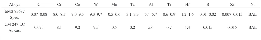
[image:1.595.44.551.681.760.2]The alloys used herein were originally melted by vacuum induction melting (VIM) at the Cannon-Muskegon Corpo-ration in USA. The alloys were remelted in an alumina crucible in a VIM furnace and poured at 1643 K into a ceramic shell mold with a CoO facecoat, at the Chung Shan Institute of Science and Technology in Taiwan. The ceramic shell mold was maintained at 1373 K. Table 1 presents the nominal composition of the as-cast alloy, which meets the
Table 1 Nominal composition (mass%).
Alloys C Cr Co W Mo Ta Al Ti Hf B Zr Ni
EMS-73687
0.07–0.08 8.0–8.5 9.0–9.5 9.3–9.7 0.5–0.6 3.1–3.3 5.4–5.7 0.6–0.9 1.2–1.6 0.01–0.02 0.007–0.015 BAL Spec.
CM 247 LC
0.075 8.1 9.2 9.5 0.5 3.2 5.6 0.7 1.4 0.015 0.015 BAL As-cast
*1Graduate Student, National Taiwan University
*2Corresponding author, E-mail: [email protected]
Honeywell EMS-73687 aerospace engineering material specification. After all cast test bars underwent hot isostatic pressing (HIP) at 1458 K/173 MPa/4 h in an atmosphere of argon, they were heat-treated in a vacuum. The heat treatment schedules consisted of multi-step solution-treat-ments from 1494 K/2 h to 1533 K/2 h, followed by argon gas fan quenching (Ar-GFQ), as depicted schematically in Fig. 1. Finally, the test bars were subject to double aging treatments at 1353 K/4 h and 1144 K/20 h, with Ar-GFQ in each stage. The just size of the test bars was 6.3 mm in diameter by 25.4 mm long. The microstructure was elucidated by optical microscopy (OM) and scanning electron microscopy (SEM).
The grain size and the area fraction of the –0 eutectic
nodules were measured using the linear intercept method.
The morphology of 0 particle and MC carbide were also
examined. Tensile tests were carried out at room temperature using an Instron 1125 mechanical testing machine at a strain
rate of 8:3104s1. The creep and rupture tests were
conducted in air at 1255 K with applied stresses of 104, 200 and 345 MPa, using SATEC M3 creep testers.
3. Results
[image:2.595.84.254.73.183.2]3.1 Microstructure and characteristics of carbides
Figure 2 depicts the typical as-cast microstructure of the fine-grain CM 247 LC superalloy. The structure comprises
–0 eutectic phases, 0 particles and MC carbides. The
primary -0 eutectic phase is present mainly at the grain
boundaries, with a small portion within the grains. The as-cast MC carbide has a predominantly script-like shape. The
[image:2.595.317.535.165.343.2]average grain size of approximately 65mm, as shown in
Fig. 3, was obtained by maintaining the pouring temperature
Fig. 1 The processes of solution-treatment in this research. GFQ represents gas fan quenching.
10 mµµ
Fig. 2 SEM micrograph showing the as-cast microstructure of fine grain CM 247 LC superalloy.
100 mµ
Fig. 3 Optical micrograph showing the grain size of fine grain CM 247 LC superalloy. The average grain size is 65mm.
(a)
(b)
1 mµµ
1 mµ
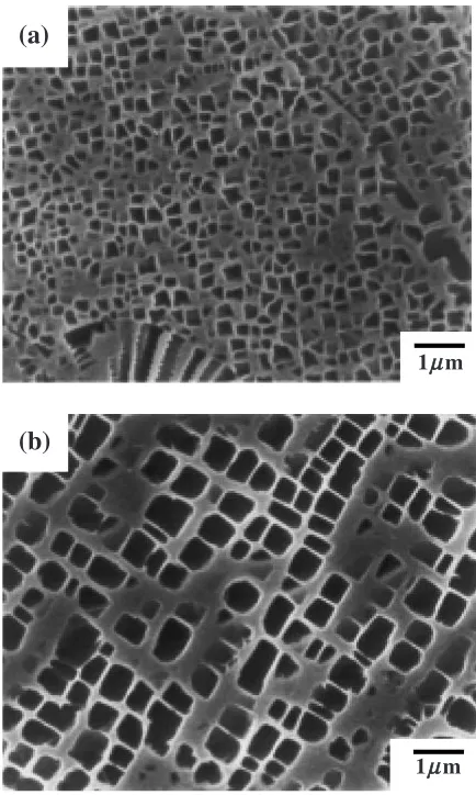
Fig. 4 SEM micrographs showing the morphology of0 particles in fine
[image:2.595.317.534.397.759.2] [image:2.595.55.284.577.756.2]about 10 K above the liquidus. The 0 particle size is about
0.3mmand the particles are spherical or cubic, as indicated in
Fig. 4(a). The low pouring temperature causes the liquid metal in this study to be more viscous than that used in conventional casting, and pores can be formed in the as-cast structure. Therefore, castings produced by the Microcast-X process must also undergo Hot Isostatic Pressing (HIP) to
eliminate all micropores.2)The high soaking temperature and
the low cooling rate cause the0particles to be slightly larger
(at about 0.5–1.0mm) following HIPing, as presented in Fig.
4(b), but with almost unchanged shapes. After HIP cycles, the
alloys were heat-treated to control the morphology of –0
eutectic phases, 0 particles and carbides to improve the
mechanical properties of the alloy.
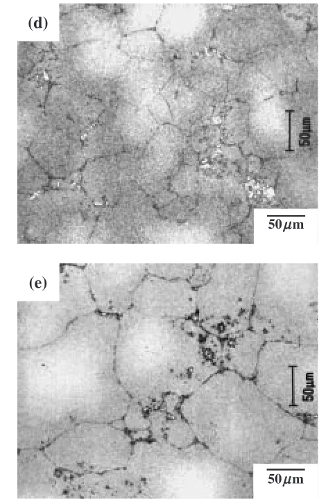
Figure 5 shows the morphology of the–0eutectic phase
after solution-treatment at various temperatures. The solution
of eutectic–0phase proceeded by increasing the multi-step
solution-treatment temperature. However, multi-step
1533 K/2 h solution-treatment is inappropriate because of slight incipient melting, which occurred as depicted in Fig.
(a)
50 mµ
(b)
(c)
(d)
50 mµ
50 mµ
(e)
50 mµ 50 mµ
Fig. 5 Optical micrographs showing the distribution and size of-0phase
[image:3.595.292.522.71.431.2]5(e). Hence, the multi-step 1527 K/2 h solution-treatment is optimal. Furthermore, Figs. 5(a)–(d) show that solution-treatment at 1494 K–1527 K/2 h did not at all influence the
grain size, which was about 60–70mm as small as the
castings. However, Fig. 5(e) indicates that the grain size after the final step at a temperature of 1533 K/2 h greatly exceeded that of the as-cast superalloy.
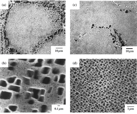
Moreover, the SEM micrograph in Figs. 6(a) and (b) show that the fine-grain CM 247 LC superalloy having undergone 1494 K/2 h + 1353 K/4 h + 1144 K/20 h heat treatment,
exhibits two0particle sizes; most particles are larger than
0.6mm. and a few are smaller than 0.05mm. In contrast, Figs.
6(c) and (d) reveal that the fine-grain CM 247 LC superalloy having undergone multi-step 1527 K/2 h + 1353 K/4 h +
1144 K/20 h heat treatment, exhibits uniformly distributed0
particle sizes from 0.3 to 0.5mm.
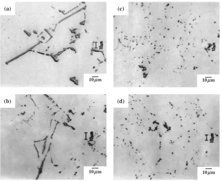
The as-cast carbide is predominantly script-like. Figure 7 shows changes of the carbide morphology after solution-treatment at various temperatures. Increasing the temperature of multi-step solution-treatment alters the morphology of the carbides from script-like to globular and discrete. Moreover, SEM/EDS (Table 2) indicates that the MC carbides are predominantly (Ta,Ti)-rich carbides. However, solution-treatment transforms the carbides into more stable
(Hf,Ta)-rich carbides.
3.2 Tensile test
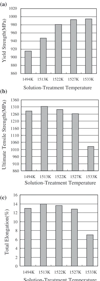
Figure 8 shows the tensile properties at 300 K of the alloys after solution-treatment at various temperatures. The yield strength increases from 915 MPa for test bars that have undergone solution-treatment at 1494 K/2 h to 993 MPa for test bars that have undergone multi-step 1527 K/2 h solution-treatment, with only a slight decline in both ultimate tensile strength and elongation, as shown in Figs. 8(b) and (c). However, after multi-step 1533 K/2 h solution-treatment, the ultimate tensile strength and ductility drop sharply. More-over, the ultimate tensile strength and total elongation have peak values at 1513 K, whilst the yield strength peaks at 1527–1533 K.
3.3 Creep and rupture tests
Figure 9 plots the stress-rupture properties of the super-alloy tested at 1255 K. When the test condition shifts from low stress (104 MPa) to high stress (345 MPa) at 1255 K, the alloy after multi-step 1527 K/2 h solution-treatment has a superior rupture life than the alloy after 1494 K/2 h solution-treatment.
(a)
(c)
(b)
(d)
10 mµµ
0.1 mµ
10 mµ
1 mµ
Fig. 6 SEM micrographs showing the distribution and size of0phase after multi-step 1494 K/2 h + 1353 K/4 h + 1144 K/20 h heat
[image:4.595.79.519.72.437.2]4. Discussion
4.1 Volume fraction and size of0 particles
Nickel-based superalloys may be strengthened by 0
precipitation in a fcc matrix. Many factors affect
strengthening by 0, including volume fraction and size of
0particle.
All the dislocation cutting models in previous reports agree
that when particles grow beyond a critical size,10,11)bypass
may occur by bowing, climbing or other processes. The
Orowan bowing model12)is generally considered to be most
applicable to austenitic superalloys. The increment in flow stress at low temperatures due to bowing, is evaluated by
considering the radius of curvature to which a flexible
dislocation can be bent by an applied stress,
b¼T=
The minimum value ofis half of the inter-particle spacingL
and corresponds to¼1=2, whereis the angle between
the dislocation line and its Burgers vector. The line tensionT
is given approximately by1=2Gb2(wherebis the magnitude
of the Burgers vector of the piled-up dislocations), but a more
exact formulation13)is
T ¼ ðGb2=4Þ’0lnðL=2bÞ;
where ’0¼1=2½1þ1=ð1Þ, and and G are the
Possion’s ratio and shear modulus of the matrix, respectively.
Additionally,Lis assumed to be the edge-to-edge spacing of
the particles. Therefore, the following expression is given for
the increment in flow stress:
¼ ðGb=2LÞ’0lnðL=2bÞ
Increasing the volume fractionf for a given particle size to
reduce L, increases the strength. The multi-step dissolving
process is more effective at 1527 K/2 h than at low temper-ature, and results in improved yield strength, due to the
increased volume fraction of finely re-precipitated0phase,
or decreased interparticle spacing (L).
The creep deformation map of a CM 247 LC-related
superalloy14) shows that the creep mechanism under the
10 mµ
(a)
(c)
10 mµ
(b)
(d)
10 mµ 10 mµ
[image:5.595.74.525.70.437.2]Fig. 7 Optical micrographs showing the morphology of carbide at various solution-treatment temperatures: (a) as-cast, (b) 1494 K/2 h, (c) 1527 K/2 h, and (d) 1533 K/2 h.
Table 2 The SEM-EDS analysis of carbide in fine-grain CM 247 LC superalloy.
Condition GB carbide Matrix carbide Casting (Ta, Ti)-rich (Ta, Ti, Hf)-rich HIPing + 1494 K/2 h
(Ta, Hf)-rich (Hf, Ta)-rich Solution-Treatment
HIPing + Multi-step 1527 K/2 h
[image:5.595.46.290.510.586.2]conditions 104 MPa–345 MPa/1255 K involves dislocation climb; that is, the creep behavior is dominated by the
interaction between dislocations and obstacles such as 0
particles or carbides. Simset al.15)stated that the0particles
in the superalloy with size from 0.25 to 0.50mm help to
inhibit dislocation climb at 1255 K.
The0phase was observed as either a spherical or a cubic
precipitate; its shape was found to be related to the
matrix-lattice mismatch. Hagel and Beattie16)observed that
precip-itates were spheres at a 0–0.2% lattice mismatch, cubes at a mismatch of 0.5%–1.0%, and plates at a mismatch higher than 1.25%.
The partial dissolution of the coarse –0 eutectic phase
and the coarse0phase at 1494 K/2 h leads to the over-aging
and growth of0particles after double aging heat-treatment
at 1353 K/4 h + 1144 K/20 h. The growth of0particles and
the reduced number of 0 particles may increase the
interparticle spacing. Therefore, when 0 particles are
exposed at 1255 K, the coarse 0 particles ripen (become
larger) at a significant rate and the interparticle spacing increases, facilitating dislocation bypassing.
Conversely, the optimal dissolution of the coarse –0
eutectic phase and the coarse0phase at 1527 K/2 h causes
the re-precipitation of a high volume fraction of0 particle
size of uniform size with a small interparticle spacing, inhibiting the bowing and climbing of dislocations.
There-fore, the loss of creep resistance during0ripening depends
strongly on the volume fraction of the re-precipitated 0
phase, because the fine-grained CM247LC superalloy with a
low volume fraction of re-precipitated 0 phase weakens
more quickly than that with high volume fraction of
re-precipitated 0 phase. Accordingly, increasing the volume
fraction of the moderate 0 phase promotes the creep
performance at 1255 K in a fine-grain CM 247 LC superalloy.
4.2 Morphology of carbide
Usually, conventionally cast nickel-based superalloys are strengthened mainly by carbide precipitation at the grain
boundary and the 0 phase in the matrix. Hence, the
morphology and distribution of carbide are crucial in determining the creep behavior and ductility of superalloys at high temperature. In the late 1970s, alloy designers added
Hf into Ni-based superalloys to produce the -0 eutectic
phase and increase the toughness of GB.17–20) However,
nickel-based cast superalloy remained brittle at elevated
temperatures.20) Fractographic observations revealed that
cracks are preferentially initiated at the MC carbide/matrix interface in Mar-M247 superalloys at elevated
temper-atures.21)Kaufman obtained the same results22)and proved
that script-like MC carbides are extremely brittle and may act
as crack initiation sites or crack propagation paths. Baldan23)
860 880 900 920 940 960 980 1000 1020
1494K 1513K 1522K 1527K 1533K
Solution-Treatment Temperature Yield Strength(MPa) (a) 860 910 960 1010 1060 1110 1160 1210 1260 1310 1360
1494K 1513K 1522K 1527K 1533K
Solution-Treatment Temperature
Ultimate Tensile Strength(MPa)
(b) 0 2 4 6 8 10 12 14 16
1494K 1513K 1522K 1527K 1533K
Solution-Treatment Temperature
Total Elongation(%)
(c)
Fig. 8 The variation of the (a) yield strength, (b) ultimate tensile strength and (c) total elongation as a function of solution-treatment temperature.
Heat Treatment : Multi-step
1527K/2h+1353K/4h+11 44K/20h
Heat Treatment : 1494K/2h+1353K/4h +1144K/20h
Rupture Time , t/h
Stress, / MPa
σ
[image:6.595.83.256.72.558.2] [image:6.595.312.543.74.271.2]also noted that the size of the carbide particles dominates the creep rupture, and that fine dispersion increases creep ductility.
In this study, increasing the temperature of the solution from 1494 K/2 h to 1533 K/2 h markedly refines carbides in the matrix and at the grain boundary, and makes them spherical. Blocky carbide particles at grain boundaries may act as dispersed obstacles that retard sliding of the grain-boundary and form barriers to crack propagation. Therefore, for the fine-grain CM 247 LC superalloy, increasing the dissolution temperature (1527 K/2 h) can promote the creep life (1255 K) and the yield strength at high temperature. Additionally, the ductility maintains at 12–13% for total elongation even though the yield strength is highly improved
by increasing the volume fraction of the uniform 0 phase.
The fine carbide particles at the grain boundaries may reduce the mobility of the grain boundaries and absorb the energy of deformation, hence both the ultimate tensile strength and the total elongation initially increase with the dissolution
temperature. Moreover, Sims24)indicated that coarse0and
–0 depletion near the grain boundary in high strength
nickel alloys may also form a ductile zone, preventing the initiation of grain-boundary fracture through enhanced the local ductility. However, increasing the dissolution temper-ature from 1494 K/2 h to 1533 K/2 h reduces the size of the ductile zone (Fig. 5), which has a low effective elastic modulus, leading to stress concentrations at the grain boundaries and reducing the absorption of energy of deformation. Hence, both the ultimate tensile strength and the total elongation decline as the dissolution temperature rises over 1513 K/2 h. Therefore, the ultimate tensile strength and elongation are maximal at 1513 K.
5. Conclusion
(1) Multi-step 1527 K/2 h solution-treatment increased the
volume fraction of relatively fine 0 particles and
refined the carbides in fine-grain CM 247 LC super-alloy.
(2) The yield strength at 300 K increased after multi-step 1527 K/2 h solution-treatment, whilst the ductility was maintained as high as 12-13% of the total elongation. (3) The creep rate and rupture life were improved after
multi-step 1527 K/2 h solution-treatment. Improve-ments of the mechanical properties are attributed to
the microstructure, and particularly the morphology of
0particles and carbides.
Acknowledgements
The authors would like to thank the National Science Council of the Republic of China for financially supporting this research under Contract No. NSC 91-2623-7-002-008.
REFERENCES
1) M. Kaufman:Proc. Superalloys 1984, M. Gell, ed., (AIME, Warren-dale, PA, 1984) pp. 43–52.
2) M. Woulds and H. Benson: Proc. Superalloys 1984, M. Gell, ed., (AIME, Warrendale, PA, 1984) pp. 3–14.
3) B. A. Ewing and K. A. Green:Proc. Superalloys 1984, M. Gell, ed., (AIME, Warrendale, PA, 1984) pp. 33–42.
4) C. T. Sims, N. S. Stoloff and W. C. Hagel:Superalloy II, (John Wiley & Sons, New York, 1987) pp. 425–426.
5) G. K. Bouse and M. R. Behrendt:Superalloy 718, E. A. Loria, ed., (TMS, Warrendale, PA, 1989) pp. 319–328.
6) K. Harris and R. E. Schwer: TMS-AIME Fall Meeting, St. Louis, MO, (1978) pp. 1–11.
7) K. Harris and R. E. Schwer: AVS 6th Int. Vac. Met. Conf., (San Diego, CA, 1979) pp. 7–8.
8) K. Harris, G. L. Erickson and R. E. Schwer: 5th Int. Symposium on Superalloys, (Champion, PA, 1984) pp. 221–230.
9) H. E. Huang and C. H. Koo: Chinese Journal of Materials Science and Engineering32(2000) 170–176.
10) R. K. Ham: Ordered Alloys; Structural Applications and Physical Metallurgy, (Claitors, Baton Rouge, LA, 1970) pp. 365–373. 11) H. Gleiter and E. Hombogen: Mater. Sci. Eng.2(1968) 285–302. 12) E. Orowan: Symposium on Internal Stresses in Metals, (Institute of
Metals, London, 1948) pp. 451–453.
13) A. Kelly and R. B. Nicholson: Prog. Mater. Sci.10(1963) 151–191. 14) C. T. Sims, N. S. Stoloff and W. C. Hagel:Superalloy II, (John Wiley &
Sons, New York, 1987) pp. 39–40.
15) C. T. Sims, N. S. Stoloff and W. C. Hagel:Superalloy II, (John Wiley & Sons, New York, 1987) pp. 208–210.
16) W. C. Hagel and H. J. Beattie: Iron and Steel Inst. Spec. (1964) pp. 98– 107.
17) J. E. Doherty, B. H. Kear and A. F. Giamei: J. Met.23(1971) 59–62. 18) D. N. Duhi and C. P. Sullivan: J. Met.23(1971) 38–40.
19) P. S. Kotval, J. D. Venables and R. W. Calder: Metall. Trans.3(1972) 453–458.
20) H. Y. Bor, C. G. Chao and C. Y. Ma: Scr. Mater.38(1998) 329–335. 21) H. Y. Bor, C. G. Chao and C. Y. Ma: Metall. Mater. Trans. A30(1999)
551–561.
22) M. Kaufman:Proc. Superalloys 1984, M. Gell, ed., (AIME, Warren-dale, PA, 1984) pp. 43–52.