Flat Cavities formed in TZP caused by Superplastic Deformations
at High Strain-Rates and Their Effect on Elongation
Stefanus Harjo
1;*, Jan Sˇaroun
2, Yoshinobu Motohashi
1, Naoki Kojima
1, Vasyl Ryukthin
2,
Pavel Strunz
2;3, Matthias Baron
4;5and Rudolf Loidl
4;51Research Center for Superplasticity, Faculty of Engineering, Ibaraki University, Hitachi 316-8511, Japan 2Nuclear Physics Institute, 250 68 Rˇ ezˇ, near Prague, Czech Republic
3Hahn-Meitner Institut, Glienicker Strae 100, D-14109 Berlin, Germany 4Institute Laue-Langevin, BP 156, F-38042 Grenoble Cedex 9, France 5Atominstitut der Osterreichischen Universitaten, A-1020 Wien, Austria
Cavitation in a superplastic 3Y-TZP pulled under different temperature and strain-rate conditions was analyzed by means of SANS techniques. In high strain-rate deformations, the formation of crack-like flat cavities with their flat surfaces lying roughly normal to the tensile axis was found, in addition to conventional cavities slightly elongated along the tensile direction having been frequently observed in superplastically deformed 3Y-TZP. Coalescence of the nearby crack-like flat cavities during the high strain-rate deformations gave rise to the generation of large brittle-like cracks, which led to an earlier fracture without apparent occurrence of necking. A mechanism for the formation of the flat cavities and their effect on the elongation are discussed.
(Received October 1, 2003; Accepted January 6, 2004)
Keywords: yttria stabilized tetragonal zirconia polycrystal, small angle neutron scattering, superplasticity, cavitation, tension, elongation
1. Introduction
As well known, cavities are formed and grown in polycrystalline materials subjecting to superplastic deforma-tions and the degree of cavitation can control the elongation to fracture in many cases. In superplastic metals, cavities slightly elongated mostly parallel to the tensile axis have been frequently observed after the deformations. The degree of cavitation increases with raising strain-rate or lowering temperature, depending on materials, testing conditions and microstructural stability.1,2)In a superplastic yttria stabilized tetragonal zirconia polycrystal (Y-TZP), a cavitation behav-ior quite similar to superplastic metals has also been observed,i.e., cavities grow and coalesce with nearby ones mostly parallel to the tensile axis with the deformation.3–5) Experimental results on Y-TZP have indicated that even small levels of cavitation may affect to the room temperature mechanical properties.6,7)
Up to date, four types of cavity shape have been found depending on temperature and strain-rate in Y-TZP speci-mens pulled superplastically: They are (i) cavities with spherical-like shapes,3,4,8)(ii) those elongated mostly parallel to the tensile axis due to their growth and/or coalescence,3–5) (iii) relatively large ones coalesced roughly normal to the tensile axis4,9)and (iv) crack-like ones lying mostly normal to the tensile axis.4) The crack-like ones were identified as intergranular cracks in a 3Y-TZP deformed under a high strain-rate condition by transmission electron microscopy (TEM).4) However, Primdahl et al.8) showed that such intergranular cracks might be also originated from the volume increase associated with the tetragonal to monoclinic transformation induced in some grains during grinding and
polishing processes to a TEM foil. Despite a large number of studies concerning cavitation behaviors in superplastic materials,3–8,10–13)only a few data — obtained from exactly as-deformed specimens,i.e., without the surface preparation — have been reported so far. It is probable that the surface preparation of specimens before the evaluation of cavitation may give errors in the data. On the other hand, an application of a small angle neutron scattering (SANS) method must be attractive because of no necessity of the surface preparation and of high penetration ability of neutrons into materials. Since the SANS method can cover a wide range of sizes ranging from about 1 to104nm, this technique is particularly useful in studies of fine flaws existing in ceramics, ceramic processing and so forth.14,15)
In our previous works,16,17)cavitation behaviors in a 3Y-TZP deformed in tension under a proper superplastic condition to various pre-determined strains were investigated by means of SANS techniques as well as the conventional methods such as Archimedes’ one. We have found from the studies that (1) fine and equi-axed cavities (type (i)) are initially generated and then they evolve with the progress of the deformation into anisotropic ones with their longest diameters roughly parallel to the tensile axis (type (ii)), and (2) the cavities with their diameters nearly equal to the average size of surrounding grains account for the largest in number among all the cavities existing in each specimen deformed to different strains.
The present work focuses on the application of SANS methods to investigate the cavitation and its morphology during tensile superplastic deformations in 3Y-TZP under wider conditions, particularly at high strain-rates, and their effect on elongation to fracture.
2. Experimental
The material used in this study is a fine-grained 3Y-TZP
*Present address: High Energy Accelerator Research Organization,
Institute of Materials Structure Science, Neutron Scattering Facility, Tsukuba, 305-0801, Japan. E-mail: [email protected]
with an initial average grain size of 390 nm. The chemical composition of the 3Y-TZP is as follows: Y2O3 = 5.15, Al2O30.10, SiO20.02, Fe2O30.01, Na2O0.04 and ZrO2= balance, in mass%. Flat tensile specimens were made to provide a gauge part of 25 mm in length, 4 mm in width and 3 mm in thickness. Tension tests at constant crosshead speeds were carried out in air. The details of testing conditions are shown in Table 1.
Characterization of cavities was performed on the gauge section of the deformed specimens by means of SANS. The SANS experiments have been conducted at a pinhole system and two types of double-crystal (DC) system instruments. The pinhole system is the collimator instrument (V4, HMI, Berlin), while the DC systems are the high-resolution double-bent-crystal instrument (DN-2, NPI, Rˇ ezˇ near Prague) and the ultra high resolution Bonse-Hart type instrument (S18, ILL, Grenoble). For measurements at the pinhole instrument, each specimen was measured at two kinds of sample-to-detector distance of 4 and 16 m, where the shorter distance realized a wider scattering vector (Q) range. The wavelength used was of 0.6 nm, and this permitted us to obtainQin a range from about 0.05 to 1 nm1. For measurements at the DC (DN-2 and S18) instruments, each specimen was measured in both vertical and horizontal orientations with respect to the scattering (horizontal) plane, in order to get information about the anisotropy of microstructures. The measurements at the DC instruments were conducted at a Q range from 3104 to4102nm1, which corresponded to the size (radius) in the real scale from about 10mm to 75 nm, respectively. More detailed description of the SANS methods used in this investigation has been reported in our previous work.17) In this study, the SANS measurements were conducted for as-deformed specimens, i.e., those without surface preparation. Microstructural evolution was observed by means of a scanning electron microscope (SEM), JSM-5310, a conventional tungsten high vacuum SEM made by JEOL. Since 3Y-TZP is a good insulator, Au coating by means of the sputtering was performed prior to the SEM observation to increase secondary electron emission.
3. Results
3.1 SANS measurements
We have chosen a testing condition of T ¼1723K and initial strain-rate,""_i, of3:3104s1,i.e., the condition D (see Table 1), as a most proper superplastic condition to deform specimens superplastically to various nominal strains.
Figure 1 shows 2-d SANS profiles of an undeformed specimen and of a specimen deformed to 198% measured at the V4 instrument with the detector located at a
[image:2.595.49.543.84.161.2]sample-to-detector distance of 16 m. Similar results were also obtained for the measurements with the detector located at the distance of 4 m. Since only asymptotic Porod scattering was observed in the measured range ofQ, no information about the sizes or volume fractions of cavities was obtained except for their
Table 1 Conditions for superplastic deformations of 3Y-TZP tensile specimens.
Condition Temperature,T/K Initial strain rate,""_i/s1 Nominal strain,e(%)
A 1623 3:3105 99
B 1623 4:0104 99
C 1723 3:3105 98
D 1723 3:3104 10198
E 1723 6:7103 100
-0.2 -0.1 0.0 0.1 0.2 -0.2
-0.1 0.0 0.1 0.2
e=0%
Horizontal Scattering Vector, Qx/ nm-1
Vertical Scattering Vector,
Qy
/ nm
-1
(a)
(b)
(c)
-0.2 -0.1 0.0 0.1 0.2 -0.2
-0.1 0.0 0.1 0.2
e=198%
1723K
3.3
×
10
-4s
-1 [image:2.595.307.548.86.632.2]total specific surfaces. However, since this instrument can provide 2-dimensional data, it is easy to see directly anisotropy of the cavity shapes. The distribution of scattering intensities with respect to the beam center was nearly circles as seen in Fig. 1(a), whereas anisotropic closed curves were seen in Fig. 1(b). The latter stems from the anisotropy of cavity shapes,16,17)i.e., their shapes were kinds of rotation-ellipsoids with longest diameters mostly parallel to the tensile axis (type (ii)) in the specimens subjected to large super-plastic strains. Meanwhile, cavities or residual pores left after the sintering process in slightly deformed or undeformed specimens were nearly spherical in shape (type (i)) or if they had initially anisotropic shapes they would be distributed randomly. Note that SANS data give dimensions in recip-rocal space. This trend is consistent with other data having been reported for superplastic Y-TZP specimens deformed under proper superplastic conditions.1,3–5) That is to say, cavities grow and some of them coalesce with nearby cavities mostly along the tensile direction with the progress in strain. The mean aspect ratio of the cavities obtained from fitting a model of cavities - the form of which is rotation ellipsoids with the longest diameter parallel to the tensile axis - to the 2-d SANS patterns 2-directly has shown that initially equi-axe2-d cavities changed their shapes into anisotropic ones by the aspect ratio of about 1.2 when the strain reached 198%.17) The aspect ratios have already been found to agree with those obtained from SEM analysis.17)
Figures 2(a) and (b) show a 2-d SANS profile of a specimen deformed to 98% at 1723 K with ""_i of 3:3
105s1 (condition C) and that of a specimen deformed to 100% at 1723 K with 6:7103s1 (condition E), respec-tively, measured at the V4 instrument with the detector located at the distance of 16 m. It is evident from Fig. 2(a) that the distribution of scattering intensities with respect to the beam center was anisotropic closed curves with horizon-tally stretched shapes, similar to those observed in Fig. 1(b), though the degree of the anisotropy was relatively low. The similar trend was observed also for a specimen deformed to 99% at 1623 K with 3:3105s1 (condition A). These results agree well with the fact that the cavities, which were generated and then grown during the deformations at low strain-rates, were kinds of rotation-ellipsoids with their longest diameters parallel to the tensile axis, i.e., type (ii) cavities. On the other hand, the distribution of scattering intensities with respect to the beam center for the specimen deformed at a higher strain-rate, 6:7103s1, at 1723 K was much complicated as seen in Fig. 2(b), where a vertically elongated pattern appeared in addition to the horizontally stretched one. The similar trend was observed also for a specimen deformed to 99% at 1623 K with 4:0104s1 (condition B).
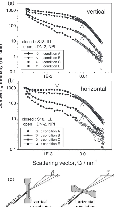
Figures 3(a) and (b) show scattering curves measured at the DC instruments for vertical and horizontal specimen orientations, respectively. It is evident that, as we expected, the scattering intensities for allQvalues increase with raising strain-rate and lowering temperature due to the increase in the volume fraction of cavities. This result corresponds to the fact that the cavitation was activated with raising strain-rate and/or lowering temperature.3,4)A careful inspection of Figs. 3(a) and (b) revealed that the curves, except for the specimen
deformed at 1723 K with3:3105s1(condition C), began to turn down at a certain value of Q(¼9103nm1, as indicated by the arrow "), making knee-like flections. The data measured for both vertical and horizontal orientations shown in Fig. 3 were fitted simultaneously, using a model with two sets of cavities having sizes (radii) varying between 20 nm and 10mm. For the first set, cavities were assumed to have shapes of spheres, while they were rotation-ellipsoids with the longest diameters parallel to the tensile direction for the second set. For the details please refer to Ref. 17). We have found that the position of the flection appeared at around Q¼9103nm1 in Fig. 3 was due to the fact that the cavities with the radii of about 200 nm occupied the major part of volume fraction of all cavities existing in the specimens deformed under conditions A, B and E. This trend is consistent with that obtained for 3Y-TZP deformed under a proper superplastic condition in our previous works.17) On the other hand, the scattering curves for the specimen deformed under the condition C were quite similar to those of undeformed specimen, showing that no significant cavitation was brought about.
The inspection of Fig. 3 also revealed that scattering curves for the specimens deformed at higher strain-rates
Horizontal Scattering Vector, Qx/ nm-1
Vertical Scattering Vector,
Qy
/ nm
-1
(a)
(b)
-0.2 -0.1 0.0 0.1 0.2 -0.2
-0.1 0.0 0.1 0.2
e
= 98%
1723K
3.3
×
10
-5s
-1-0.2 -0.1 0.0 0.1 0.2 -0.2
-0.1 0.0 0.1 0.2
e
=100%
1723K
6.7
×
10
-3s
-1(conditions B and E) showed additional interference peaks at aQvalue around1:62103nm1 (shown by the arrow #) for the case of horizontal specimen orientation. The additional interference peak position was determined from the peak of the residual between the measured data and the fitted curve based on the fitting procedure described above. However, no such additional peaks appeared for the vertical specimen orientation. This indicates that, the additional interference peaks in the measurement for the horizontal specimen orientation may stem from the presence of pores or defects having strong-anisotropic shapes. That is to say, their parts (surfaces) normal to the tensile direction were large enough to be detected by DC-SANS instruments, while their parts parallel to the tensile direction were too small to be detected. Therefore, these additional peaks must be caused by the presence of flat pores or defects18)(hereafter referred to as
flat cavities) with their flat surfaces lying mostly normal to the tensile axis. TheQvalue at the additional peak position indicates that the flat cavities are being distributed along the tensile direction with the average interval of approximately 34mm. Therefore, the vertically elongated pattern appeared in Fig. 2(b) can be explained by the presence of these flat cavities with their flat surfaces lying mostly normal to the tensile axis. The existence of such flat cavities was hardly observed in specimens deformed under proper superplastic conditions. The formation (generation) of these very fine crack-like flat cavities ends up with a decline in the elongation to fracture as will be discussed later. The existence of these flat cavities will be confirmed by micro-structural observations as shown later in this paper.
[image:4.595.55.285.75.492.2]3.2 Microstructural observation by SEM
Figure 4 shows SEM images for specimens deformed to
1E-3 0.01
0.1 1 10 100 1000
closed : S18, ILL open : DN-2, NPI
Scattering vector,
Q
/ nm
-1 : condition A: condition B : condition C : condition E
1E-3 0.01
0.1 1 10 100 1000
closed : S18, ILL open : DN-2, NPI
: condition A : condition B : condition C : condition E
Scattering Intensity (rel. unit)
(a)
(b)
(c)
vertical
horizontal
Fig. 3 Scattering curves measured at the DC (DBC and Bonse-Hart)-SANS instruments for specimens deformed to approximately 100% under various conditions. Specimens were oriented (a) vertically and (b) horizontally with respect to the scattering (horizontal) plane, as shown in (c). ": flections indicating the average cavity size for the largest in number,#: additional interference peaks due to the presence of flat defects (cavities).
(a)
(b)
(c)
C
E
E
[image:4.595.326.527.285.747.2]approximately 100% under the conditions C and E. These specimens were subjected to thermal-etching for 1.8 ks at a temperature 100 K lower than that used for the deformations. In an image taken at a high magnification for the specimen deformed under the condition C (Fig. 4(a)), no significant cavitation was found while the grains evolved. Cavities or pores observed in the specimen were isolated and appeared to be almost in spherical shapes (type (i)). They may, therefore, be residual pores left after the sintering or small-cavities formed in the early stages of the deformation. For the specimen deformed under the condition E (Fig. 4(b)), as we expected from the SANS results, the cavities with their number quite larger than that found in Fig. 4(a) were observed. Many of the cavities are isolated and have a mean diameter less than 1mm. They were, on average, slightly stretched to the tensile direction, being in good agreement with the result of SANS measurement at V4 shown in Fig. 2(b), i.e., the scattering intensity distribution was slightly stretched horizontally. The existence of the flat cavities with their flat surfaces lying mostly normal to the tensile axis, which is predicted from the SANS results, however, was difficult to identify in the SEM image shown in Fig. 4(b). It was also difficult to identify them in the SEM image taken at the same magnification on the polished gauge section without thermal etching. This may be due to their sizes (gaps) much smaller than the limited resolution of SEM used here. This will be discussed later in this article. Meanwhile, in the SEM image taken at a low magnification (Fig. 4(c)), no large cavities coalesced mostly normal to the tensile axis (type (iii)) were seen. This means that the vertically elongated pattern shown in Fig. 2(b) was not due to type (iii) cavities.
4. Discussion
4.1 Confirmation of the existence of flat cavities from microstructural and mechanical aspects
In order to confirm the existence of flat cavities, not only by the SANS method but also other ones, we have pulled mirror-like polished 3Y-TZP tensile specimens (1) under a proper superplastic condition (T¼1723K, ""_i¼4:3
104s1, hereafter refers to as PSC) and (2) under a high strain-rate condition (T ¼1723K,""_i¼6:7103s1, here-after refers to as HSC) to their fractures; they were 490% and 170% in nominal strain, respectively. This was done because it seemed that some of the flat cavities would have grown up to be detected by SEM at the strain close to its fracture limit. Appearances of cavities for the specimen deformed to the fracture under PSC are shown in Figs. 5(a)–(d), while those under HSC are shown in Figs. 5(e)–(g).
It is evident from Figs. 5(a) and (b) that, at a region close to the fractured part in the specimen deformed under PSC, very large crack-like cavities lying roughly normal to the tensile axis,i.e.type (iii) ones were being formed. On the other hand, in the specimen deformed under HSC, no such type (iii) cavities were observed (see Fig. 5(e)). The type (iii) cavities, appeared in the specimen deformed under PSC, were observed only at the region close to the fractured part and were not identified at the region 6 mm apart from the fractured part, as shown typically in Fig. 5(c). In addition, it was found from the fracture surfaces shown in Fig. 6 that the
fracture modes for both specimens were intergranular ones. It was also found in Fig. 6 that both grain size and unevenness of the fracture surface in the specimen deformed under PSC are larger than those in the specimen deformed under HSC. These results indicate that the fracture in the specimen deformed under PSC was caused by the conspicuous coalescence of the large crack-like cavities, which deter-mined its fracture limit, while the fracture under HSC might be caused by the propagation of intergranular cracks formed out of the coalescence of the flat cavities.
Figure 5(d) shows an enlarged image of a rectangular part indicated in Fig. 5(c), where many cavities with their diameters larger than 1mmwere found, but no tendency of the cavities to coalesce normal to the tensile axis was observed. This suggests that, in the specimen deformed under PSC, only the cavities existing close to the fracture-surface-to-be coalesced to form the large crack-like cavities (type (iii) ones) and one or some of them was grown to form transverse cracks to lead to fracture (Fig. 5(a) or (b)).
On the other hand, as mentioned above, in the specimen deformed under HSC, no type (iii) cavities were observed even at the region close to the fractured part (Fig. 5(e)). Instead, a number of flat defects or fine cracks existing along the grain boundaries roughly normal to the tensile axis were identified when observed at higher magnification as shown in Fig. 5(f). These defects were also found at regions 6 mm apart from the fractured part, as shown typically in Fig. 5(g). Moreover, these defects were distributing roughly about 7mm interval along the tensile direction. This distance corresponds fairly well with the average separation interval of the flat cavities estimated from SANS, if we take a probability that there must still be many flat cavities with their gaps under the SEM resolution limit or still in a closed state into consid-eration. It is probable, therefore, that most crack-like defects appearing in Figs. 5(f) and (g) may be full-grown flat cavities, the species identified from SANS measurement made at the nominal strain of about 100%.
was identified though the conventional cavities were formed in it. From the above reasons, the strain softening appeared in the S-S curve for the specimen deformed under HSC may be due to the formation of a large number of the crack-like flat cavities in it.
Recently, we have found from SANS measurements that flat cavities can be generated even in early stages of the deformation in specimens pulled at relatively high strain-rates.19) The fact that the S-S curves have shown strain
softening from the beginning of the deformation supports this result.
4.2 Formation mechanism of flat cavities and their effect on elongation
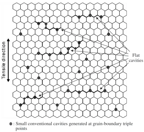
Figures 5(f) and (g) suggest that the flat cavities would be formed by coalescence of nearby small conventional cavities existing at grain boundary triple points through separation of grain boundaries lying among them mostly normal to the (a)
500 µm
(b)
50 µm fractured part
(b)
(c)
50 µm 20 µm
(d)
(e) (f)
20 µm
fractured part
500 µm (f)
20 µm
(g)
T
e
nsile direction
Fig. 5 Appearances of cavities: (a)–(d) in specimen deformed to fracture (490%) at 1723 K with4:3104s1; and (e)–(g) in specimen
[image:6.595.124.472.70.604.2]tensile axis. This result, i.e., the flat cavities were intergra-nular crack-like ones, is supported also by the fact that the fracture surface of the specimen deformed under HSC showed a plane-like surface with overall intergranular fracture (see Fig. 6(b)). From these experimental facts, the formation mechanism of the flat cavities can be deduced as follows: Although the flow stress is usually quite low under PSC, conventional cavities can be generated and grown at some grain boundary triple points where stress concentration caused by grain boundary sliding is large enough to produce
the cavities there. Meanwhile, under HSC or under low temperature conditions, since the flow stresses were higher, more cavities should be formed at grain boundary triple points than under PSC (compare Figs. 4(a) and (b)). That is to say, a great number of fine cavities can be generated in early stages of the deformation in the specimen deformed at high strain-rates or at low temperatures. Such trend of the cavitation is verified in the microstructures after the deformations (see Figs. 4(b) and (c)). Moreover, under these conditions the flow stress was so high that grain boundaries existing among the small conventional cavities mostly normal to the stress axis would be relatively easy to separate under the action of tensile stress, since the bonding strength of the grain boundary in a temperature region where superplasticity arises might be relatively weak. This idea is upheld by the fact that the fracture surfaces of the specimens deformed under HSC and PSC were both intergranular ones overall (see Figs. 6(a) and (b)). We think, therefore, that the above-mentioned process would be a main mechanism of the generation of the flat cavities, which is schematically illustrated in Fig. 9.
Now, let consider an effect of the flat cavities on the superplastic elongation of 3Y-TZP. Limited elongations have
(b)
5 µm 5 µm
(a)
Fig. 6 Appearances of fracture surface: for (a) deformation under a proper superplastic condition (PSC); and (b) a high strain-rate condition (HSC).
Undeformed
Deformed at 1723K, ε0= 6.7 x 10⁻³s-1
ef= 170 %
.
Fig. 8 Macroscopic view of tensile specimens before and after its fracture.
60
40
20
0
True stress,
σt
/ MPa
150 100
50 0
True strain, εt (%) High strain rate cond. (HSC)
Proper cond. (PSC)
Fracture HSC : 1723K, 6.7 x 10⁻³ s-1 PSC : 1723K, 4.3 x 10⁻⁴ s-1
Fig. 7 True stress-true strain curves for deformations under HSC and PSC conditions.
Flat cavities
: Small conventional cavities generated at grain-boundary triple points
[image:7.595.69.269.69.418.2] [image:7.595.314.541.73.197.2] [image:7.595.310.541.245.458.2] [image:7.595.68.271.470.623.2]been observed in superplastic deformations under high strain-rate or low temperature conditions. As found in this study, the flat cavities can be formed along grain boundaries roughly normal to the tensile axis depending on the deformation condition, and, if formed, they would decrease the elongation to fracture. The generation of the flat cavities depended strongly on the applied tensile stress. That is to say, the flat cavities can be generated more easily under higher strain-rate or lower temperature conditions where the flow stress becomes higher. This would lead to a lower elongation due to the coalescence and/or the propagation of the flat cavities along transverse (cross-sectional) direction of the specimen. Meanwhile, the generation of the flat cavities should depend also on the grain boundary cohesion and it is probable that the weaker the cohesion the greater the generation. Recently, it has been reported20–22)that an addition of dopants which segregate and alter the chemical bonding state at and nearby grain boundaries sensitively changes the elongations to fracture of TZP. More recently, Kuwabara et al.23) have shown that the elongation to fracture of TZP has a close relation with covalency at and nearby grain boundaries; an addition of dopants, which enhances the covalency, improves the elongation considerably. They23)have explained that the enhancement of the grain boundary covalency makes grain boundary cohesion stronger and suppresses intergranular failure accordingly. Combining the results of Kuwabara et al.23)with our present ones, we can conclude that the addition of dopants, which enhances covalency and accordingly cohesion of grain boundaries, can suppress the formation of the flat cavities.
Considering the above-mentioned things, one can draw a conclusion that: (1) For superplastic ceramics having almost the same grain boundary cohesion, the flat cavities can be formed more easily when the applied tensile stress becomes higher, and as a result smaller elongation will occur. (2) The addition of dopants, which can suppress the generation of flat cavities even when the stress applied to the specimen is high, improves the elongation as well. The former idea coincides with the results given by Kim et al.,24) while the latter coincides with that shown by Kuwabara et al.,23) though qualitatively. In conclusion, it is most probable that whether the generation of flat cavities is easy to occur or not is a crucial phenomenon to determine the elongation to fracture of superplastic ceramics.
Next, let consider reasons why the flat cavities were difficult to observe by means of SEM when the deformation amount (strain) was around 100% in nominal strain. The gaps in the flat cavities would be opened under tensile stress and they therefore decreased the effective cross sectional area of the specimen greatly during the deformation, but when the tensile stress was removed the gaps of the flat cavities might become small or some of them might be closed. Taking this into consideration, the flat cavities dispersing with the average interval of 34mm along the tensile direction measured from the DC-SANS experiments would be those that were in open state at room temperature. Since the SANS experiments were not conductedin situ, flat cavities which were in closed state might not be able to identify due to the limited resolution of the DC-SANS instruments. In addition, we have deduced from the thermal expansion measurements
for a specimen deformed under a high strain-rate condition that an average gap in flat cavities would be less than 3 nm and therefore it was difficult to identify by SEM.25)
The resolution of SEM (JSM-5310) used in this study is 4 nm. However, this value is the one measured at the best condition of the JSM-5310. For the SEM observation of the 3Y-TZP in this study, we coated Au on the surface prior to the observation and used an accelerating voltage of 5 kV since the specimen contamination occurred when the voltage higher than 5 kV was used. Taking this condition into consideration, the resolution of SEM observation for our study might be about 10 nm or worse. Therefore, we think it was difficult to identify the flat cavities by means of the SEM in this study. There is a possibility to use a semi-in-lens cold cathode Field Emission SEM to detect the flat cavities if the coating method to increase secondary electron emission can be improved, since the SEM with this type have a very high resolution of about 1 nm even at the accelerating voltage of 1 kV.
The facts that, (1) 3Y-TZP specimen fractured without any apparent necking when deformed under the high strain-rate condition, though the S-S curve showed sharp strain soften-ing, (2) little microstructural evolution was observed during the deformation, and (3) the fracture mode was the intergranular one, can also explain the existence of flat cavities. To study the effects of the flat cavities on the mechanical, thermal, electrical and chemical properties, must be very interesting and is our future subjects. To find a proper treatment for getting rid of the flat cavities, if necessary, is also our future task.
3Y-TZP may be also due to a fact that the former one was subjected to the high temperature creep deformation and the latter one the superplastic deformation.
5. Conclusions
Cavitation behaviors in 3Y-TZP specimens deformed superplastically under various deformation conditions were analyzed by means of small angle neutron scattering (SANS). Main conclusions are as follows:
(1) The SANS method can detect crack-like flat cavities having very small gaps, which may be difficult to identify by the conventional method such as by a scanning electron microscopy.
(2) During superplastic deformations at high strain-rates, a number of crack-like flat cavities having very small gaps lying mostly normal to the tensile axis were formed in addition to conventional ones. The generation of these flat cavities seemed responsible for the apparent strain softening appeared in the S-S curve. (3) The growth and coalescence of the flat cavities were
related to the formation of brittle-like cracks, which would lead to an earlier fracture without apparent occurrence of necking, resulting in the decrease in the total elongation, i.e., the formation of the flat cavities seemed to be a crucial phenomenon to determine the elongation.
(4) It is deduced that the flat cavities were formed by coalescence of nearby small conventional cavities existing at grain boundary triple points, which were generated in early stages of the deformation in the specimen pulled at high strain-rates, through separation of grain boundaries lying among them mostly normal to the stress axis under the action of tensile stress.
REFERENCES
1) N. Ridley and Z. C. Wang:Superplasticity, 60 years after Pearson, ed. by N. Ridley (1995) pp. 63–74.
2) D. Pulino-Sagradi, A. M. M. Nazar, J.-J. Ammann and R. E. Medrano: Acta Mater.45(1997) 4663–4666.
3) Y. Ma and T. G. Langdon: Acta Metall.42(1994) 2753–2761.
4) Z. C. Wang, N. Ridley and T. J. Davies: J. Mater. Sci.34(1999) 2695– 2702.
5) S. Tekeli and T. J. Davies: Mater. Sci. Eng. A297(2001) 168–175. 6) Y. Motohashi, T. Sekigami and N. Sugeno: Mater. Processing Tech.68
(1997) 229–235.
7) Y. Motohashi, N. Sugeno, S. Koyama and T. Sakuma: Mater. Sci. Forum243–245(1997) 399–404.
8) S. Primdahl, A. Tholen and T. G. Langdon: Acta Metall. Mater.43 (1995) 1211–1218.
9) D. J. Schissler, A. H. Chokshi, T. G. Nieh and J. Wadsworth: Acta Metall. Mater.39(1991) 3227–3236.
10) H. Iwasaki, T. Mori, M. Mabuchi and K. Higashi: Mater. Trans., JIM41 (2000) 367–375.
11) F. Musin, R. Kaibysev, Y. Motohashi, T. Sakuma and G. Itoh: Mater. Trans.43(2002) 2370–2377.
12) H. Hosokawa, M. Mabuchi, H. Iwasaki and K. Higashi: Mater. Trans. 43(2002) 2415–2418.
13) S. Tekeli: Mater. Lett.57(2002) 715–719.
14) P. Strunz, J. Saroun, P. Mikula, P. Lukas and F. J. Eichhorn: J. Appl. Crystallogr.30(1997) 844–848.
15) A. J. Allen, S. Krueger, G. G. Long, H. M. Kerch, H. Hahn and G. Skandan: Nanostructured Materials7(1996) 113–126.
16) S. Harjo, Y. Motohashi, N. Kojima, J. Saroun, V. Ryukhtin, P. Strunz and P. Lukas: in Proc. ofThe 4th Pacific Rim International Conference Advanced Materials Processing (PRICM4), ed. by S. Hanadaet al., (2001) pp. 2057–2060.
17) S. Harjo, N. Kojima, Y. Motohashi, J. Saroun, V. Ryukhtin, P. Strunz, R. Loidl and M. Baron: Mater. Trans.43(2002) 2480–2486. 18) R. F. Reidy, A. J. Allen and S. Krueger: J. Non-Cryst. Solids285(2001)
181–186.
19) V. Ryukhtin, J. Sˇaroun, S. Harjo, Y. Motohashi, A. Wiedenmann and P. Strunz: in Proc. of ECNS 2003, Montpellier, 3-6 September 2003. 20) Y. Ikuhara, K. Sasaki, P. Thavorniti and T. Sakuma: in Proc ofThe 3rd
Pacific Rim International Conference Advanced Materials Processing (PRICM3), ed. by M. A. Imamet al., (1998) pp. 1747–1754. 21) Y. Ikuhara, P. Thavorniti and T. Sakuma: Acta Mater.45(1997) 5275–
5284.
22) P. Thavorniti, Y. Ikuhara and T. Sakuma: J. Am. Ceram. Soc.81(1998) 875–883.
23) A. Kuwabara, S. Yokota, Y. Ikuhara and T. Sakuma: Mater. Trans.43 (2002) 2468–2472.
24) W.-J. Kim, J. Wolfenstine and O. D. Sherby: Acta Metall. Mater.39 (1991) 199–208.
25) C. Wan, Y. Motohashi and S. Harjo: Mater. Trans.44(2003) 1053– 1056.
26) J. R. Porter, W. Blumeuthal and A. G. Evans: Acta Metall.29(1981) 1899–1906.