Basal-Texture Induced Low Formability
during Room Temperature Hydroforming of Fine-Grained AZ31 Mg Tubes
C. C. Huang
1, J. C. Huang
1;*, Y. K. Lin
2and Y. M. Hwang
2 1Institute of Materials Science and Engineering, National Sun Yat-Sen University, Kaohsiung, Taiwan 804, R. O. China 2Department of Mechanical and Electromechanical Engineering, National Sun Yat-Sen University,
Kaohsiung, Taiwan 804, R. O. China
The microstructures and mechanical properties of the AZ31 Mg tubes fabricated by one-pass forward piercing tube extrusion are examined. The grain size is refined from the initial75mmgrain size down to 2–3mm. The room temperature uniaxial tensile elongations, measured along an axis that is 0, 45, or 90with respect to the extrusion direction, are satisfactory, ranging from 20 to 50%. However, room
temperature tube hydroforming, under a more complicated stress state, results in poor formability as a result of the strong basal plane texture. Rationalization in terms of Schmid factor analysis on the data obtained from the pole figures yields consistent results. Solutions for such difficulty are proposed.
(Received June 9, 2004; Accepted September 1, 2004)
Keywords: magnesium alloy, tube hydroforming, tensile property, texture
1. Introduction
Magnesium alloys have been considered as advanced materials for coping with energy conservation and environ-mental pollution regulations, and are applied for parts in automobile, aircraft or aerospace industry where lightweight metals are needed to minimize weight or reduce internal forces at high accelerations. During the past five years, applications in automobile, bicycle, and 3C (computer, communication and consumer electronic) products become rapidly extended.1–3)Among many Mg based alloys, the AZ (Mg-Al-Zn), AM (Mg-Al-Mn) and ZK (Mg-Zn-Zr) based alloys seem to be the most popular; with the AZ91 and AZ31 alloys being cheaper and occupying the highest market.
Due to the hexagonal crystal structure nature of the Mg alloys, deformation at room temperature is limited. Refine-ments of the grain structure using rolling, extrusion, or equal channel angular pressing down to 10mmor below have been demonstrated to enhance the deformation capability.4–6) Rolling at room or elevated temperatures tends to cause side cracking. In contrast, extrusion at elevated temperatures will result in satisfactory products in the form of bars, plates, or sheets.
The room temperature tensile elongations for commercial Mg alloys after grain refinement can reach 20–50%.4,7) Furthermore, low temperature superplasticity and/or high strain rate superplasticity at 200–400C and 104–101s1 could be developed in such fine grained Mg alloys.1,4,5,8)The processed alloys in the form of rods or plates may exhibit sufficient ductility allowing room or elevated temperature forming practices.
The current forming practices for Mg based alloys are mostly conducted through die casting or press forming at elevated temperatures. Lowering the forming temperature is always beneficial in terms of energy and budget saving. In this study, the AZ31 Mg billet, with an initial grain size of
75mm, was one-pass warm extruded into long tubes with nearly equiaxed fine grains. Most previous studies on the forming of Mg based alloys are focused on the products in the form of rods, thick plates, or thin sheets. There have been very limited reports addressing the tube forming feasibility. The current paper presents the room temperature tensile and hydroforming behaviors of the extruded tubes. And the tube forming performance is rationalized in terms of the resulting texture and anisotropy properties.
2. Experimental
The AZ31B (Mg-3 mass%Al-1 mass%Zn) billet, fabricat-ed through semi-continuous casting, was purchasfabricat-ed from the CDN Company, Deltabc, Canada. The initial grain size is
75mm. Small cylindrical rods 65 mm in diameter were machined from the billet, and warm extruded by the forward and seedless extrusion method,9,10)with self-designed pierc-ing mandrel die and unloadpierc-ing attachments. The extrusion reduction ratio for this case was only 15.4, equivalent to a true processing strain of 2.7. The extrusion temperatures and strain rates varied from 250 to 400C and 6103 to 1100s1. The extrusion strain rate was calculated based on the equation of ""_¼"ext=t, where the strain "ext is equal to (6v=DÞlnR11) and v is the extrusion speed, D is the input material diameter, and Ris the extrusion reduction ratio. It was found that more consistent results were obtained from extrusion with higher temperatures (300–400C) and lower strain rates (6103–1102s1), and only such results are presented in this paper. After extrusion, the tubes were statically annealed at 400C for 4 h in order to improve room temperature hydrofroming formability.
With the extrusion ratio of 15.4, a thicker tube with the outer and inner radii of 15 and 12.5 mm (or a tube wall thickness of 2.5 mm) was extruded. Such tubes may be applied in forming into Mg bicycle frames or motorcycle pipes. In order to compare the hydrofoming formability, a thinner tube was prepared by subsequent machining of the *Corresponding author, E-mail: [email protected]
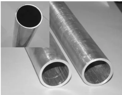
tube wall down to 1.3 mm, with the outer and inner radii of 15 and 13.7 mm. The grain structures of the thick and thin tubes are the same. The resulting Mg tubes with shining inner and outer surfaces and uniform thickness are shown in Fig. 1.
Room temperature tensile tests are performed on the tubes with the tensile loading axis aligned along 0, 45, and 90 with respect to the extrusion direction, with a strain rate of 1103s1. The gauge length of the mini tensile specimen is 5.5 mm in length, 3 mm in width, and 2 mm in thickness, The 45 and 90 tensile specimens were machined from the flattened tube warm-pressed at 200C. The grain structures of the as-extruded and annealed tubes are examined by optical microscopy (OM). The grain texture revealed from the inner wall is performed by X-ray diffraction (XRD) using a Cu K radiation.
The experimental apparatus used for tube hydroforming is a self-designed test machine, composing of a tube expansion set, a hydraulic power system, and a pressure intensifier, as depicted in Fig. 2. The budge degree is traced by an inserted dial height-meter. The capacity of this test machine can reach a hydro-pressure of 100 MPa.
3. Results and Discussion
3.1 Microstructure
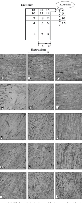
The material flow during the forward and seedless tube extrusion has seldom reported. The flow lines during tube extrusion might seem to be predictable and impose nil significance, but in this study they appear to correlate to the gradual texture evolution. Figure 3 shows the low magnitude OM micrographs for various positions on the upper half of the extruded billet. Position 15 is referred to the tube to be extruded out of the die, and it can be seen clearly the horizontal and parallel flow lines (and later found to be parallel to the traces of {0002} basal planes as presented in Sec. 3.3). In contrast, near the dead zone in positions 2 and 3, the original randomly oriented structures in the billet are still maintained. During extrusion at 250–400C, the materials in different locations gradually flow towards the outlet for the tube wall, and the basal plane was rotated gradually to align along the extrusion direction. The typical equiaxed grain structures in the extruded tubes are shown in Fig. 4(a). It has
been shown that the AZ31 Mg alloys can be rapidly recrystallized during warm working.4–6) Though the extru-sion ratio was only 15.4, the resulting grain structures are mostly recrystallized and equiaxed fine grains, measuring 2–3mm. Upon static annealing at 400C for 4 h, the grains grow to 5–8mm, as compared in Fig. 4(b). It should be noted that a lower extrusion temperature (<250C) and a faster strain rate (>100s1) would result in appreciable partial recrystallization unfavorable for subsequent hydro-forming. The variation of the resulting grain size as a function of extrusion strain rate and temperature is shown in Fig. 5. The higher extrusion temperature and lower extrusion strain rate both result in higher grain size, but the temperature effect is much more apparent then the strain rate within the regime examined. The grain size follows well the Hall-Petch relationship with respect to the Hv hardnesss, as presented in Fig. 6, according to the equation of
Hv¼26þ69d1=2: ð1Þ
3.2 Room temperature tensile properties
Within the optimum extrusion conditions, the average room temperature UTS and elongation data on the as-extruded tubes along the extrusion direction (i.e. the 0 specimens) loaded at1103s1are scattered within 290– 310 MPa and 25–32%. Upon static annealing at 400C for 4 h, the data are changed to 250–265 MPa and 35–45%, respectively. Representative results are presented in Table 1. The highest tensile elongation achieved for the 0 tube specimens was 51%, which is an exceptionally high tensile elongation for Mg alloys. High room temperature tensile elongations have also been reported in a number of AZ31 rod or plate specimens processed by equal channel angular pressing7)or high ratio extrusion.5,6)It was expected that the AZ series Mg alloys with refined grain size and high room temperature ductility might be likely to be press-formed at room temperature.
Since the hydroforming would proceed at a higher strain rate to 102–101s1, selected tensile tests of the fully annealed 0 specimens were conducted at1101s1. The UTS data remain nearly unchanged, while the elongation values decrease only slightly to 30–40%, still promising in terms of ductility.
Selected tensile tests were also applied to the 45and 90 Fig. 1 Warm-extruded AZ31 Mg tubes (2.5 mm in thickness) with shining
outer appearance. Inserted is the tube with a thinner thickness of 1.3 mm.
Pressure Relief Pressure Input
Upper Fixed Die
Window
Lower Die Insert Upper Die Insert
Urethane Ring
Lower Fixed Die Lower Plate Containment Vessel
Upper Plate
[image:2.595.68.267.71.226.2] [image:2.595.316.536.77.213.2]AZ31 tubes Unit: mm
[image:3.595.154.441.69.779.2]specimens after annealing at 400C for 4 h, and the results are included in Table 1. A notable decrement is observed for the tensile elongation, to a level around 20–30%. Nevertheless, such a uniaxial tensile ductility in the AZ31 Mg alloy is still higher or compatible to the tensile elongations observed in the Al alloys (15%) used for room temperature tube hydro-forming to satisfactory hydro-forming limit.12)Thus it is expected that the room temperature tube hydroforming of the current Mg tubes should exhibit reasonable formability.
3.3 XRD texture results
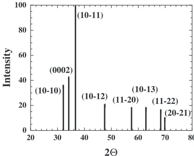
[image:4.595.48.291.73.188.2] [image:4.595.73.265.249.412.2]The X-ray diffraction experiment is performed on a smaller square area measuring 5mm7mm of the inner tube wall after full annealing at 400C for 4 h. Slight grinding was done to ensure a flat surface facing the incident X-ray. Figure 7 shows the simulated pattern for completely random Mg powders, which can be compared with the typical XRD results shown in Fig. 8. The as-received billet exhibit an X-ray diffraction pattern (Fig. 8) close to the random case in Fig. 7. It can be easily seen that there exists a strong {0002}
10 µm
(a) (b)
Fig. 4 Optical micrograph showing the grain structure of the AZ31 Mg tube extruded at 300C: (a) under the as-extruded condition, and (b) under
the extruded and then fully annealed condition.
.
10-2
10-1
100
0.0 0.5 1.0 1.5 2.0 2.5 3.0
Grain Size,
d
/
µ
m
Strain Rate, /s-1
250°C 300°C 350°C 400°C
ε
Fig. 5 The variation of the grain size as a function of extrsuion strain rate and temperature for the AZ31 tubes.
0.60 0.65 0.70 0.75 0.80 0.85 0.90 0.95 1.00 60
65 70 75 80 85 90 95 100
Hv = 26 + 69 d-1/2
Hv Hardness
d-1/2 / µm-1/2
Fig. 6 The Hall-Petch plot for relationship between the the hardness and grain size of the AZ31 tubes.
Table 1 Room temperature tensile results of UTS (in unit of MPa) and elongation for different orientations of the tube specimens extruded at different temperatures and strain rates and annealed at 400C for 4 h.
ExtrusionT
(C)
Extrusion""_
(s1) 0 45 90
300 6103 259/37% - -
-300 1102 253/40% 266/28% 277/26% 400 6103 261/38% 265/28% 264/19%
400 1102 258/37% - -
-20 30 40 50 60 70 80
10000 15000 20000 25000 30000 35000 40000
(0002)
(20-21) (11-22)
(10-13) (11-20) (10-12) (10-11)
(0002) (10-10)
300°C, 1x10⁻² s-1 400°C, 6x10⁻³
s-1
AZ31 billet
Intensity
2
θ
Fig. 8 XRD patterns for the as-received AZ31 billet (nearly random), and the tubes extruded at 300C and1102s1or 400C and6103s1. The strong {0002} peak is overwhelming for the latter two cases.
0 20 40 60 80 100
20 30 40 50 60 70 80
Intensity
2Θ
(10-10) (0002)
(10-11)
(10-12) (11-20)(10-13)(11-22) (20-21)
Fig. 7 Simulated X-ray diffraction pattern for the completely random Mg using the Cu-Kradiation. Within 30–40, the (10110) and (0002) peak
[image:4.595.330.521.340.494.2] [image:4.595.73.263.472.619.2] [image:4.595.313.541.565.745.2] [image:4.595.46.289.710.784.2]basal plane texture in the extruded specimens, independent of the extrusion temperature or strain rate. All extruded tubes after full annealing exhibit an apparent and simple basal texture, with the {0002} basal plane lying parallel to the thin tube wall all over the tubes.
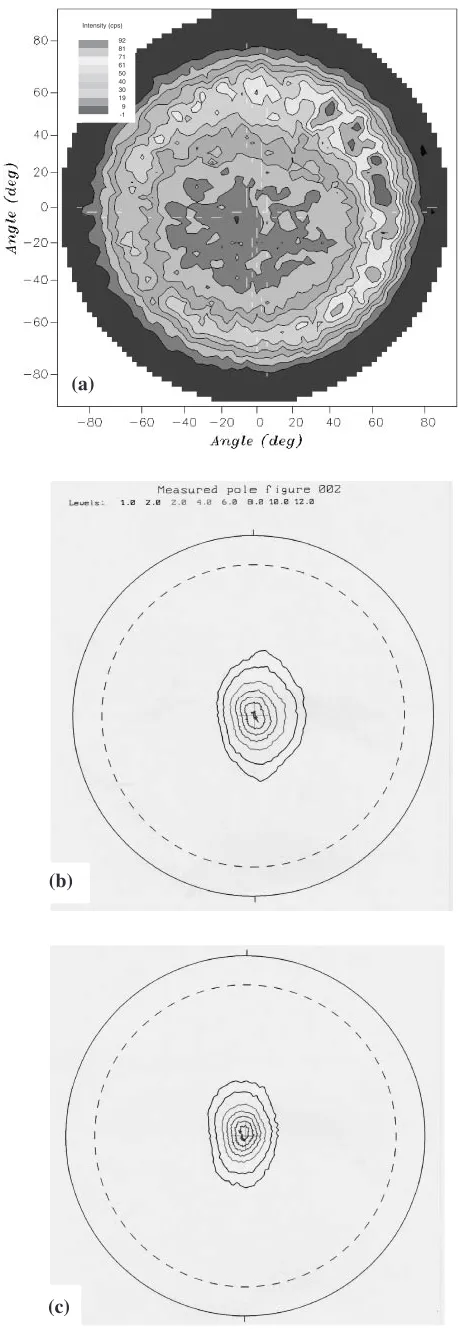
A more clear presentation for the simple basal plane texture can be seen from the pole figure (Fig. 9) obtained from the as-received billet and extruded tubes. To protect the X-ray detector, the pole figures were constructed up to around 75, rather than 90. The texture in the as-received billet is not pronounced and several maxima dispersed in the pole figures. In contrast, after tube extrusion, a predominant (0002) basal plane texture is observed. The similar pole figures as those shown in Figs. 9(b) and (c) were obtained in tubes extruded at 250–400C and103–100s1. From Fig. 9, it is noted that the preferred orientation extends from the ideal {0002} basal texture (at the center point) outward to around 20. This means that the basal texture still has some scattering and limited grains are orientated within20from the ideal {0002} texture.
The presence of a basal plane texture has been widely observed in hot rolled or hot extruded thin plates or sheets,13,14) but was not thoroughly reported in extruded seamless thin tubes. It is observed now that the predominant plane texture is also present in the thin Mg tube. Numerous checks were made to bombard the X-ray in different regions, and the simple basal texture is consistently seen. The {0002} basal planes show a strong tendency to align parallel to the extrusion direction.
3.4 Tube hydroforming behavior
Preliminary room temperature tube bulging using the as-extruded tubes, with room temperature UTS of300MPa, has encountered tremendous difficulty due to the high working pressure required. Tube bulging on the AZ31 tube fully annealed at 400C for 4 h, with UTS of 260MPa, exhibits slightly improvements. By fitting the tensile flow stress by the simplified power law, the true stress can be expressed as
¼K"n; ð2Þ
where K and n are the strength coefficient and work hardening exponent, respectively. The yield stress is not considered here so that the computing time for bulging simulation could be considerably shortened. In average, K andn are 458 MPa and 0.25 for the fully annealed tube 0, 45 or 90 specimens. Tensile properties along the radius direction are unable to be measured.
The tube is hydroformed at room temperature using special oil into an asymmetric elliptic shape. Both the tubes with wall thicknesses of 2.5 mm and 1.3 mm were formed. For the thicker 2.5 mm and thinner 1.3 mm tubes, the bulged tubes were found to crack at oil pressure levels around 50 and 22 MPa, respectively. For all forming experiments, the forming limits were considerably low as compared with previous room temperature tube hydroforming for the 6061 Al.12)This might be a result of several factors. Firstly, there might be extrusion defects causing the premature failure (as an example in Fig. 10). Secondly, a lower ductility occurs at the high bulging strain rate (102–101s1). Thirdly, and
(b) Intensity (cps)
92 81 71 61 50 40 30 19 9 -1
(a)
(c)
[image:5.595.311.540.72.737.2]most importantly, the presence of strong basal plane texture would severely suppress budging extension along the non-basal direction, as described later.
The bulge heights, h, as a function of hydroforming bulging pressure, P, for the tubes with tube thicknesses of 2.5 mm and 1.3 mm are established, as shown in Fig. 11. With the experimentally obtained materials properties ofK andndata extracted from the tensile tests and using a self-written mathematical model for bulging forming
proc-ess,15–17) the effective stress and strain values can be
extracted from the hydroforming experiments. The latter data are compared with those obtained from the uniaxial tensile tests, as shown in Fig. 12. The extracted K0 and n0 values from the bulging degree of the hydroformed tubes are 821 MPa and 0.34 for the 2.5 mm tubes (greater than those of the tensile results), and 401 MPa and 0.22 for the 1.3 mm tubes (slightly lower than those of the tensile values). Since the bulging extent of the 2.5 mm tubes is rather low and the bulged tubes tend to fail with limited plastic strain, the fitting of the extracted effective stress and strain values is subject to
much greater uncertainty. This is particularly significant when the simple power law, i.e., eq. (2), is in use, since eq. (2) is applicable when the plastic strain is much larger than the elastic strain, so that the elastic strain can be ignored. It is considered that the extractedK0andn0values based on the thinner 1.3 mm tubes would be more rational and reliable. Nevertheless, the bulging height or the plastic strain of the 1.3 mm tubes are still limited as compared with our previous work on the Al based alloys. Therefore, the overall agreement between theKandndata obtained from the tensile (458 MPa and 0.25) and bulged (401 MPa and 0.22) specimens is at most fair. If the tube diameter increases, the tube wall thickness decreases, or the bulging temperature increases, the bulging height could be increased and the fitting agreement could be improved accordingly.
3.5 Limited formability due to texture
Our previous room temperature tube hydroforming on the 6061 Al alloy with a tensile elongation around 15% has yielded successful formability.12,18)However, the current Mg tubes, even with higher tensile elongations of 20–40% along the 0, 45, and 90 directions with respect to the extrusion axis, exhibited much poorer bulge heights. It appears that the planar basal texture imposes strong influence on the tube formability.
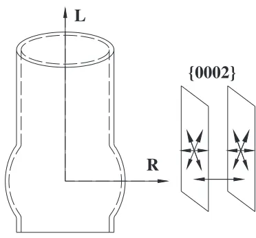
For Al tubes with a face-centered cubic structure and mixed texture of Copper, Brass, and Goss types, appreciable room temperature formability can be provided by dislocation cross slip onto the numerous plane families. In contrast, the simple and predominant {0002} basal plane texture lying on all over the tube wall, coupled with the lack of non-basal cross slip during room temperature tube bulging, make the hexagonal close-packed Mg tubes can only undergo planar slip, rather than 3D uniform deformation. Since the grain orientation exhibits plane texture, it means that the fine grains on the tube wall are oriented in a 2D random condition. The [0001] c-axis is perpendicular to the tube wall, but the orientations on the {0002} basal plane, such as [11220] or [10110], are all randomly distributed. The f0002gh11220i
a-typed dislocations can slip easily on the {0002} basal
0 10 20 30 40 50 60
0 0.5 1 1.5 2 2.5 3
2.5 mm 1.3 mm
Bulging Pr
essur
e,
P
/MP
a
[image:6.595.56.283.71.243.2]Bulging Height,
h
/mm
Fig. 11 Variation of the hydroforming bulging pressure as a function of bulging height near the hemisphere for the extruded and then fully annealed AZ31 tube with a tube wall thickness of 2.5 or 1.3 mm.
[image:6.595.321.534.75.246.2]10 mm
Fig. 10 A brittle premature vertical crack observed from the outer tube wall.
0 100 200 300 400
0 0.1 0.2 0.3 0.4
Tensile test data Hydroforming, 2.5 mm Hydroforming, 1.3 mm
Effecti
v
e
T
rue Str
ess, /
MP
a
Effective True Strain
σ
[image:6.595.62.279.300.483.2]plane. It follows that a higher tensile elongation under the uniaxial tensile stress state would still be achieved when the specimens are loaded along an axis parallel to the basal plane. But such dislocations can hardly make cross slip to non-basal planes such as f10110g, f10111g, or f11222g, as depicted schematically in Fig. 13. With nearly all grains with basal planes lying parallel to each other, dislocation motion has to be confined to 2D planar slip. Tube bulging into a 3D elliptic shape is thus difficult.
The stress states for the tube hydroforming are much more complicated than the unaxial tensile testing. At the beginning of the bulging stage, a multiple stress state including all of the circumferential, meridional, and radial stresses. Until the bulged shape becomes elliptic or near semi-half-circular in shape, the stress state at the pole approaches biaxial stress condition with the radial stress being negligible. Whether under the biaxial or triaxial stress states, the principal shear stresses on several slip systems would be considerably reduced, as compared with the unaxial tensile stress state.19) It can be easily realized from the Mohr’s circles.19)The lower resulting shear stresses would also suppress the plastic deformation capability. It was found in this study that the bulged region tends to fail before forming the well defined elliptic or half-circular shape. The strong basal texture with minimum cross slip capability becomes difficult to respond the multiple stresses, particularly for the radial stress.
The ease of plastic deformation at room temperature is usually judged from the orientation Schmid factor calcula-tion, S, where S¼coscos and and are the angles between the slip plane and direction with respect to the tensile axis, respectively. It has been mentioned above that
[image:7.595.57.550.94.150.2]the strong basal plane texture would always allow some minor orientaton scattering within 20, as evident from Fig. 9 and our previous extensive texture characterizations on the Mg base alloys in terms of pole figures or orientation distribution functions.20)The calculations of Schmid factors are only done for the ideal and exact {0002} plane texture. Since the predominant slip system for Mg at room temper-ature is only the f0002ghai type, the rest of prismatic or pyramidal slip systems are excluded in the current estima-tion.
Table 2 lists the calulated Schmid factor values along the direction that is 0, 45, or 90 with respect to the extrusion direction (or the tube longitudinal axis) in response to the applied circumferential, meridional, and radial stresses. It can be seen that, for the ideal {0002} texture, the average Schmid factors are around 0.11 for the circumferential and meri-dional stresses, and basically zero for the radial stress. Nevertheless, the 20 relaxation would raise the average Schmid factors to 0:2 for the circumferential and meri-dional stresses, and 0:1 for the radial stress. Since unidirectional tensile straining of the tube-wall specimens would basically require the straining along the tensile axis, similar to the extension along the circumferential direction. A Schmid factor of0:2is sufficient to activate thef0002ghai
type dislocations on the basal planes. The initial stage of the tube bulging could also be considered to be a circumferential tension, and the limited straining could proceed to some extent. With further bulging, the radial stress becomes important, and the dislocations could hardly respond to the radial stress due to much lower Schmid factors (00:1) under such orientations.
Based on the Schmid factor calculations, the relative ease in the dislocation activity and plastic formation can be estimated. With the much lower dislocation mobility in response to the radial stress to form into an asymmetric elliptic shape, plastic deformation cannot proceed smoothly and microcracks and premature failure would be induced soon, severely constraining the formability limit of the bulged tube. It follows that room temperature tube bulging for tubes possessing a strong basal textue is inevitably diffiuclt.
3.6 Suggestions for hydroforming of Mg tubes
[image:7.595.74.260.177.350.2]In our experience, the {0002} plane texture is widely present in all rolled and extruded Mg sheets and plates. It is demonstrated now to be present in the Mg tubes as well. Follow-up annealing would not alter much. Two solutions are postulated here. Firstly, our parallel studies of these extruded AZ31 Mg tubes loaded at 300–400C have shown reasonable superplasticity of 400–600%.21) Superplasticity at lower temperatures of 150–200C would drop to 100–250%, but Table 2 Summary of the Schmid factor calculations for the basal slip system,f0002ghai, along three representative loading directions of
the 0, 45, and 90with respect to the extrusion axis in the extruded AZ31 tubes.
Stress 0 45 90
Circumferential Average 0.10 Average 0.11 Average 0.11
(or meridional) 1=3ð0þ0:15þ0:15Þ 1=3ð0:17þ0:12þ0:05Þ 1=3ð0:17þ0:08þ0:08Þ
Radial Average 0 Average 0 Average 0
{0002}
R
L
appears to be sufficient for tube hydroforming. Grain boundary sliding and grain rotation would both occur at such elevated temperatures, accompanied by considerable dislocation cross slip onto the non-basal planes. Thus the {0002} plane texture problem is overcome. It means that hydroforming of Mg extruded plates or tubes needs inevi-tably to be operated at elevated temperatures. Secondly, the forming limit might be improved with the modification of existing textures. Our parallel studies on the friction stir processing have shown the ability to modify locally the texture of the extruded bars and plates.22)Through one pass of the friction stir processing, the texture can be significantly changed into nearly random orientation. It is postulated that local modification of the current {0002} plane texture in the extruded tubes might be achieved as well by the friction stir processing on the regime where a higher formability limit is needed. Due to the lack of suitable fixtures for the thin tubes, this experiment is not able to be performed in our laboratory. But such a proposition might still act as postulated solution. With more random or multiple textures, the Mg alloys might be more suitable to be formed at ambient temperature.
4. Summary
One-pass forward piercing tube extrusion operated at 300– 400C and 103–102s1 has been applied on the AZ31B Mg billets, refining the initial 75mm grain size down to 2–3mm. The room temperature tensile elongations of the as-extruded or fully annealed tube specimens along the 0, 45, and 90directions with respect to the extrusion direction are all scattered within 20–45%. Even after full annealing at 400C for 4 h, there still exists a strong and predominant {0002} plane texture on the tube wall. Such a texture seriously limits the room temperature tube hydroforming, due to the fact that dislocations can hardly make cross slip onto the non-basal plane to result in 3D uniform deformation. Since the basal plane texture is widely present in all rolled or extruded sheets or tubes, it is inevitably necessary to invoke forming at elevated temperatures around 200–300C. Other-wise, modifications of the plane texture need to be done through, for example, local friction stir processing on the critical regime requiring a higher formability limit.
Acknowledgements
The authors gratefully acknowledge the sponsorship from National Science Council of Taiwan, ROC, under the project number NSC 91-2216-E-110-006.
REFERENCES
1) M. Mabuchi, H. Iwaski, K. Yanase and K. Higashi: Scr. Mater.36
(1997) 681–686.
2) M. Mabuchi, K. Kubota and K. Higashi: Scr. Mater.36(1997) 1249– 1254.
3) E. Aghion and B. Bronfin: Mater Sci. Forum350–351(2000) 19–28. 4) H. K. Lin and J. C. Huang: Mater. Trans.43(2002) 2424–2432. 5) H. K. Lin and J. C. Huang: Key Eng. Mater.233–236(2003) 875–880. 6) Y. N. Wang, C. J. Lee, C. C. Huang, H. K. Lin and J. C. Huang: Mater.
Sci. Forum426–433(2003) 2655–2660.
7) T. Mukai, M. Yamanoi, H. Watanabe and K. Higashi: Scr. Mater.45
(2001) 89–94.
8) M. Mabuchi, T. Asahina, H. Iwasaki and K. Higashi: Mater. Sci. Tech.
13(1997) 825–831.
9) G. E. Dieter:Mechanical Metallurgy, (McGraw-Hill Book Co, London, UK; 1988) p. 631.
10) K. Laue and H. Stenger: Extrusion Processes, Machinery, Tooling, (American Society for Metals, Metals Park, Ohio; 1989) p. 63. 11) S. Kalpakjian:Manufacturing Processes for Engineering Materials.,
(3rd ed., Addison-Wesley, Menlo Park, California, USA; 1997) p. 342. 12) Y. M. Hwang and M. T. Yang: Key Eng. Mater.233–236(2003) 311–
316.
13) J. A. del Valle, M. T. Perez-Prado and O. A. Ruano: Mater. Sci. Eng.
A355(2003) 68–78.
14) Y. N. Wang and J. C. Huang: Mater. Chem. Phys.81(2003) 11–26. 15) Y. M. Hwang and Y. K. Lin: J. Mater. Processing Tech.125–126
(2002) 821–825.
16) Y. M. Hwang and Y. K. Lin: Key Eng. Mater.233–236(2003) 317– 322.
17) Y. K. Lin, C. C. Huang and Y. M. Hwang:Proceedings of International Conference on Advanced Materials Processing Technologies, (AMPT’01, Madrid, Spain, 2001). Vol. II, pp. 931–937.
18) Y. M. Hwang, Y. K. Lin, H. C. Wu and H. C. Chen:Proceeding of the 18th National Conference of CSME, (Taipei, Taiwan, ROC; 2001). pp. 311–314.
19) G. E. Dieter:Mechanical Metallurgy, (McGraw-Hill Book Co, London, UK; 1988). p. 36.
20) Y. N. Wang and J. C. Huang: Mater. Trans.44(2003) 2276–2281. 21) C. C. Huang, J. C. Huang, Y. K. Lin and Y. M. Hwang: Key Eng.
Mater.271–271(2004) 289–294.