Importance of the Adhesion of HVOF Sprayed Coatings
for Aqueous Corrosion Resistance
*Seiji Kuroda
1, Jin Kawakita
1, Takeshi Fukushima
1and Shogo Tobe
2 1National Institute for Materials Science, Tsukuba 305-0047, Japan
2Ashikaga Institute of Technology, Ashikaga 326-0845, Japan
Importance of coating adhesion in an aqueous corrosion environment was studied experimentally. Tensile adhesion strength of HVOF sprayed 316L stainless steel and Hastelloy C coatings were tested in as-sprayed condition as well as after immersion in seawater. It was found that the adhesion strength of the stainless steel coatings degraded rapidlywhereas that of the Hastelloycoatings remained almost intact. Specimens with an artificial defect were also immersed in seawater. The cross sectional observation after the test revealed that the corrosion at the coating-substrate interface proceeded much faster with the stainless steel coating as compared to the Ni-base alloycoating. A model experiment to simulate the galvanic corrosion of a coating-substrate couple was carried out and no significant difference in the galvanic current densitywas found between the two coatings when coupled with the steel substrate. The tightness of the coating-substrate interface was then tested with a fluorescent dye penetration test. The dye could penetrate the boundary between the stainless steel coating and the substrate whereas the boundarybetween the Ni-base alloycoating and the substrate was so tight that no penetration occurred. The penetration behavior of the dye into the micro-gaps at the coating-substrate boundarywas discussed from the viewpoint of classical Washburn-Rideal theoryapplied to a model of capillaryflow between a pair of parallel circular disks. It was concluded that such micro-gaps between the coating and substrate must be eliminated for these barrier-type coatings to be used in corrosive environments. Heat treatment was highly effective for suppressing the preferential corrosion at the coating-substrate boundary.
(Received August 8, 2002; Accepted January9, 2003)
Keywords: thermal spray, high velocity oxy-fuel (HVOF), adhesion, corrosion, seawater, fluorescent dye penetration, stainless steel, Hastelloy, capillary flow
1. Introduction
Adhesion of surface coatings is a critical but not fully understood property. High Velocity Oxy-Fuel (HVOF) thermal sprayis a relativelynew thermal spraytechnique, which propels powder material bya supersonic flame jet to velocitywell over 500 m/s. HVOF sprayed coatings are attractive for corrosion resistance, as theyare dense with reduced oxidation of raw materials as compared to coatings formed byother atmospheric thermal sprayprocesses such as plasma sprayor wire arc spray. In a previous report, we evaluated the corrosion resistance1)of HVOF sprayed 316L stainless steel and HastelloyC coatings in artificial seawater. It was found that with a commercial HVOF sprayapparatus powered bykerosen, HastelloyC coatings can be fabricated to such a high densitythat the porositywithin the coating is below the detection limit of a mercuryporosimeter used, which was about 0.3 vol%. On the contrary, the minimum porosityobtained with 316L stainless steel coatings was just below 1 vol%. Consequently, the corrosion performance of the stainless steel coatings was rather poor: the corrosion rate as evaluated byan AC impedance technique degraded to the level of bare steel substrate after 3 days of immersion in seawater. In contrast, HastelloyC coatings retained high resistance and exhibited little rusting even after 1 month of immersion test in laboratory.
Another concerns for this type of coatings is galvanic corrosion. Even with a perfectlydense coating, if it should be damaged during service and thus allow seawater to penetrate
through the coating to the substrate, severe corrosion of steel substrate is expected due to the potential difference between the noble coating and steel. The large ratio of cathode to anode area will further accelerate the corrosion process. Such situation will lead to a rapid propagation of corrosion at the coating-substrate interface and result in a large-scale failure of the coating, which must be prevented. Therefore, it is essential to evaluate the stabilityof the coating-substrate interface in a corrosive media before it can be put into real use. In order to examine the stabilityof the coating-substrate interface in a corrosive media, an artificial defect was made into a coating bydrilling a hole through the coating to the substrate and the specimen was immersed in seawater. It was found that the interface of 316L stainless steel coating corrodes at a much faster rate as compared to that of HastelloyC coating. In this paper we examine the mechanism of such interfacial corrosion in more detail and demonstrate the importance of coating adhesion in a corrosive environ-ment.
2. Experimental Procedures
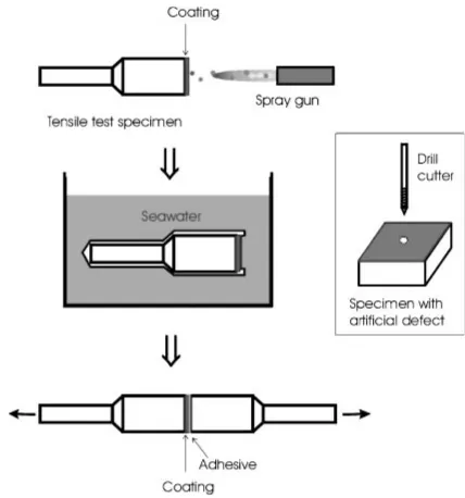
316L stainless steel and HastelloyC powders were sprayed bya high-pressure HVOF spraying equipment (JP5000, TAFA, Concord, NH, US) onto standard tensile adhesion test specimens of 25 mm diameter made of SS400 (JIS) mild steel as shown in Fig.1. These powders are gas-atomized spherical powders manufactured byTAFA (product name: 1236F for SUS316L, 1268F for HastelloyC respectively) with the size range of 22 to 53mm. The chemical composition of the powders and substrate are listed in Table1 and the spraying conditions are given in Table2. Substrates were blast cleaned with alumina grit and degreased in acetone
*Most of this paper was presented at the Int. Thermal SprayConf. 2001,
ultrasonicallybefore spraying. Coating thickness was aimed at 400mm. Adhesion strength was measured in the as-sprayed condition and after immersion in aerated artificial seawater kept at 300 K. Before immersion, plastic molding and silicone resin were used to seal the specimen to allow only the coating surface to be exposed to seawater.
In order to investigate the corrosion along the coating/ substrate interface, a hole with 1 mm diameter was drilled from the coating surface to the substrate as shown in the inset of Fig. 1 and the specimen was immersed in seawater thereafter. After 72 h it was taken out to examine the cross section.
Galvanic current between a coating of each material and a mild steel substrate in artificial seawater at 300 K was
measured bya setup as shown in Fig.2. Ideallya detached coating should be used for this experiment but seawater could penetrate into a porous coating and reach the spot-welded joint between the contact rod made of 304 stainless steel and the coating. Since such complication must be avoided for reliable measurement, a coating sprayed onto a Hastelloy C276 substrate was used as the coating specimen instead, assuming that the substrate is so inert that it will not interact with seawater. It was designed to simulate the corrosion at the interface between a coating with narrow through-pores by providing oxygen gas to the coating while suppressing the oxygen concentration on the steel substrate by bubbling nitrogen gas into the anode cell. The unit consists of a pair of cells connected bya glass filter (40 mm dia.t5 mm) with pore size ranging from 150 to 250mm, which was used to suppress the diffusion of oxygen across the cell boundary while allowing current to flow with negligible resistance. A stainless steel rod was spot-welded to each specimen and silicone resin was used to define the area of exposure of both specimens as 2 cm2. A zero-resistance ammeter was inserted
between the coating (cathode) and the substrate (anode) to monitor the galvanic current while a high-input impedance voltmeter was used to monitor the potential of the coating specimen with respect to the Ag/AgCl reference electrode.
In order to examine the tightness of the coating-substrate interface, a modified pin-test specimen was designed for fluorescent dye penetration test. The procedure is depicted in Fig.3. (1) A metal pin (SUS304, 2 mm diameter) was Fig. 1 Specimen preparation for tensile test after immersion in seawater
and a specimen with an artificial defect made bydrilling a 1 mm diameter hole through a coating.
Table 1 Chemical composition of the spraypowders and the substrate.
(Mass%) SUS316L Fe bal, Cr 16.8, Ni 10.8, Mo 2.05, N 0.131, O 0.026
[image:2.595.60.274.70.299.2]HastelloyC Ni bal, Mo 16.95, Cr 16.57, Fe 6.21, W 4.52, Mn 0.72, Co 0.31, Si 0.73 Low carbon steel Fe bal, C 0.11, Si 0.22, Mn 0.5, P 0.017, S 0.016
Table 2 List of HVOF sprayconditions for the powders used in the experiments.
SUS 316L HastelloyC Fuel flow rate (l/min) 0.322 0.379 Oxygen flow rate (sl/min) 850 861
Fuel/oxygen ratio 0.7 0.82
Barrel length (mm) 102 102
Powder feed rate (g/min) 70 59
Torch velocity(mm/s) 700 700
Spraydistance (mm) 380 380
Powder feed gas Nitrogen Nitrogen 1.0 corresponds to the stoichiometric mixture.
[image:2.595.348.502.71.283.2] [image:2.595.49.291.474.586.2]inserted at the center of a tensile test specimen (SS400, 25 mm diameter) and the surface was alumina sand blasted. Then, (2) HVOF coating was formed to a thickness of about 400mm and (3) a counter block was joined to the coating surface byusing an epoxyadhesive. (4) The pin was pulled out bya tensile test machine and (5) a fluorescent dye (Super Glo OD-7000, MARKTEC, Tokyo, Japan) was poured into the hole and left for a predetermined period (30 min, 2 h, and 24 h). (6) Post emulsifier (OD-1700B, MARKTEC) was poured into the hole to make the remained penetrant on the surface soluble bywater and the hole was washed with water and dried with air blow. Then, (7) the coating was detached bythe tensile test machine and brought into a dark room, where (8) the substrate surface was observed and photo-graphed under an UV light illumination to measure the extent of dye penetration.
Coated specimens were heat treated in vacuum at temperatures of 1023, 1173 and 1323 K for 1 h respectively to investigate the effect of diffusion across the coating-substrate boundaryon the corrosion resistance of the inter-face. Then, artificial defect was made bydrilling a 1 mm diameter hole and the specimens were immersed in aerated seawater for cross sectional observation as described above and the extent of corrosion at the interface was measured. Diffusion profile of alloying elements was measured by
3. Results and Discussion
3.1 Adhesive strength after immersion
Figure4 shows the change in adhesion strength with the immersion period. The solid plots represent the average values of 5 specimens and cross plots represent each test value. Error bars are the standard deviations. Even though the two coatings possessed similar adhesion strength around 60 MPa in the as-sprayed condition, the strength degraded to less than 20 MPa in 72 h for the SUS 316L coatings whereas it remained relativelyhigh for the HastelloyC coatings even after 30 days. A typical cross section of 316L stainless steel coatings immersed in artificial seawater for 72 h is shown in Fig.5, which exhibited severe corrosion at the coating/ substrate interface. This corrosion was caused bypenetration of seawater through porosityin the coating but the rate of corrosion is remarkablyhigh. The cross sections of the coatings with a drilled hole after immersion are shown in Fig.6. The interface corrosion for the SUS coatings
Fig. 3 Procedure to applyfluorescent dye penetration test to the interface between a thermal sprayed coating and the underlying substrate.
0 100 200 300 400 500 600 700 800
0 25 50 75
SUS316L
Hastelloy C
Immersion period t /h
Adhesiv
e strength
σ
/MP
a
Fig. 4 Change in the adhesion strength of HVOF sprayed coatings of SUS316L and HastelloyC immersed in aerated artificial seawater. represents each measured value,l the average, and error bars are the
standard deviations.
100µm
[image:3.595.53.282.71.447.2] [image:3.595.312.540.345.507.2] [image:3.595.313.541.587.755.2]proceeded as long as 5 mm whereas it was onlyabout 1 mm for the HastelloyC coating.
3.2 Galvanic corrosion test
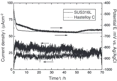
Galvanic corrosion test between each of the coatings and a mild steel substrate was carried out in order to examine if such difference in the rate of interfacial corrosion between the two coating-substrate systems discussed in the previous section is due to the difference in the rate of galvanic corrosion. Figure7shows the result of the galvanic corrosion experiment as depicted in Fig.2. It shows that the galvanic current densitybetween each of the coatings and the steel substrate is similar at around 30mAcm2and the potential is
around650mV vs. Ag/AgCl. Therefore, the results indicate that there is not a significant difference between the two coatings in terms of cathodic activitywith respect to the steel for galvanic corrosion (This maybe as expected because the free corrosion potentials of both materials in seawater lie in a same range.2)).
3.3 Fluorescent dye penetration test
Tightness of the coating-substrate interface was examined bythe fluorescent dye penetration test shown in Fig.3.
Figure8shows the surface of steel substrates under UV light illumination after fluorescent dye penetration test for each period. These photos were taken for the 316L stainless steel
(a)
(b)
Fig. 6 Cross section of 316L stainless steel (a) and HastelloyC coating (b) with an artificial defect after 72 hours of immersion in aerated artificial seawater.
0 10 20 30 40 50 60 70
0 25 50 75 100
SUS316L Hastelloy C
-1000 -900 -800 -700 -600 -500 -400
0 10 20 30 40 50 60 70
0 25 50 75 100
SUS316L Hastelloy C
-1000 -900 -800 -700 -600 -500 -400
Time t /h
Current density
i
/µ
Acm
-2
P
otential
E
/
mV vs
. Ag/AgCl
Fig. 7 Measured current densityand electrode potential of the galvanic couples as function of time. Cathodes are 316L stainless steel and HastelloyC coatings formed on HastelloyC-276 alloysubstrates. Anode is SS400 mild steel.
(a)
(b)
(c)
5mm
[image:4.595.61.541.72.243.2] [image:4.595.310.544.297.460.2] [image:4.595.69.534.598.754.2]coatings. Therefore, the results suggest that the existence of such thin gaps under the 316L stainless steel allowed rapid penetration of seawater under the coating and hence was the reason behind the marked difference in the rate of corrosion along the coating-substrate boundarybetween the two systems. According to the classical Washburn-Rideal equa-tion for the penetraequa-tion of liquid into a capillary, the periodt required for the liquid to penetrate for a distance lwithin a capillaryof radiusRis expressed as
l2¼Rcos
2 t; ð1Þ
where is the surface tension,the coefficient of viscosity of the liquid and the wetting angle of the liquid on the capillarysurface.3,4)Penetration distance was read from the photos in Fig. 8at each period and related with eq. (1) but it was found5)that experimental values oflare better related to tbythe relationshipl3/t.
As a more realistic model for the gaps in between the coating and the substrate, a radial capillaryflow between a pair of circular disks as shown in Fig. 9was analyzed. The upper plate has a hole of radiusRo from which the liquid is
supplied and penetrates radiallyinto the gap of height h between the two plates. The following expression for the penetration distance l was derived (see Appendix for derivation).
l2 2 ln l
Ro
1
þR2o¼2hcos
3 t: ð2Þ
Comparison between the model calculation using eq. (2) and the experimental data is shown in Fig.10. Three curves in the figure correspond to the calculated distance of penetrationl-Rofrom the edge of the hole in the upper plate
(substrate) for three different values ofh. It is evident that the experimental data do not fit to a curve with anyvalue of h. The data indicate that the flow decelerated as a function of time at a much greater rate than the model prediction. Also, the values ofhused in the calculation are probablytoo small for such flow calculation to be valid. Possible explanation of
the discrepancybetween the model calculation and much slower rate of penetration observed in the experiment are the followings.
(1) Measurement bya mercuryporosimeter revealed that the SUS316L coating has a porositylevel of about 1 to 2 vol%, majorityof which exist in the radius range between 10 nm and 100 nm.1) Therefore, it is possible that significant amount of dye which penetrated laterallyto a certain radius through the coating-substrate boundarywas absorbed verticallyinto the coating. If the size of the micro-gaps between the coating and the substrate is comparable or smaller than the pore size in the coating, this diversion of the liquid into the coating could reduce the supplyof liquid for further spreading along the coating-substrate boundary and hence decelerate the penetration rate.
(2) The micro-gap between the coating and the substrate cannot be a simple planar gap as assumed in the model of Fig.9. There must be some areas of contact between the coating and the substrate. How this will affect the capillaryflow is not clear at the moment.
Therefore, estimation of the size of micro-gaps between the SUS316L coatings from the time-penetration data was not successful. It should be noted that the porosityof HastelloyC coatings was below the detection limit of the mercury porosimeter (less than 0.3 vol%).1) These data seem to indicate that HastelloyC powder has a higher deformability as compared to SUS316L powder at the impact onto the substrate and coating surface but further studyis necessary.
3.4 Heat treatment
Figure11 shows the effects of heat-treating temperature on the cross sections of corrosion test specimens of SUS316L coatings with an artificial defect. The photos show that heat treatment even at a modest temperature of 1023 K is remarkablyeffective for reducing the rate of corrosion along the interface. At higher temperatures, the interface becomes more corrosion resistant due to the diffusion of corrosion resistant elements such as Cr and Ni from the coating to the substrate. Figure12 shows the penetration distance as Fig. 9 Capillaryflow of liquid between a pair of parallel circular disks. The
[image:5.595.320.529.73.256.2]liquid is fed from the hole with radiusRosituated at the center of the upper plate. The gap between the plates ishand the distance of penetration from the center isl.
[image:5.595.72.264.593.742.2]functions of the treating temperature for the two kinds of coatings as a summaryof these experiments. Figures 13(a) and (b) show the atomic concentration profiles of chromium across the coating-substrate boundaryfor the 316L stainless and HastelloyC coatings before and after heat treatment at
these temperatures.
Considering the fact that the diffusion layer for the two types of specimens at 1023 K is so narrow as 1mm, its effect on the suppression of interfacial corrosion is rather remark-able. This suppression of interfacial corrosion maybe attributed to narrowing or closure of micro-gaps between the coatings and the substrate but further studyis necessaryto clarifythis point. At higher temperatures, the diffusion layer becomes thicker than 20mmand the chromium concentration profile extends deeper into the steel; nickel was also found to behave similarly, providing higher corrosion resistance to the top layer of the substrate. Such graded composition profile is ideal for prevention of coating failure caused byinterfacial corrosion because the interface is not attacked preferentially anymore as shown in Fig.11at 1323 K.
4. Conclusions
[image:6.595.64.536.70.453.2]Even though the adhesive strength of HVOF coatings is generallybetter than that of coatings sprayed byother atmospheric thermal sprayprocesses, when a coating-substrate couple is exposed to a corrosive media, the interface can be preferentiallyattacked. In this study, 316L Fig. 11 Effects of heat treatment in vacuum on the interfacial corrosion of 316L stainless steel coatings due to an artificial defect.
Specimens were immersed in aerated artificial seawater at 300 K for 3 days. (a) as sprayed, (b)1023 K1 hr, (c)1173 K1 hr, (d)
1323 K1 hr.
900 1100 1300
Hastelloy C SUS 316L
As sprayed
Treating temperature T /K
Distance
l-Ro
/mm
6
5
4
3
2
1
0
[image:6.595.65.276.514.668.2]stainless steel and HastelloyC coatings were HVOF sprayed onto mild steel substrates and tested in artificial seawater by several testing methods including mechanical, electrochemi-cal and fluorescent dye penetration techniques. The following results were obtained.
(1) The adhesion strength of the stainless steel coatings degrades rapidlyin seawater whereas that of the Hastelloycoatings remains almost intact. When sea-water is allowed to reach the interface between the coating and the substrate, corrosion proceeds preferen-tiallyalong the interface. The rate of such interfacial corrosion is much faster with the stainless steel coating as compared to the Ni-base alloycoating.
(2) Such difference is not due to the electrochemical properties of these coatings because the galvanic current between each of these coatings and steel substrate is almost the same with each other.
(3) The interface between the HastelloyC coating and the steel substrate is so tight that fluorescent dye cannot penetrate into, whereas it can penetrate into the inter-face of the 316L stainless coating. In order to analyze the penetration mechanism, the classical Washburn-Rideal theoryhas been extended to a radial viscous flow between parallel circular disks. The expression for the distance of penetration in terms of time has been obtained and compared with the experimental data. Agreement is not good and the porosityof coatings is considered as a major reason behind the discrepancy. (4) Heat treatment above 1023 K for 1 h significantly
improves the durabilityof the coating-substrate inter-face in seawater, which is due to the enhancement of coating adhesion and the diffusion of alloying elements into the steel substrate.
Acknowledgements
We would like to thank Messrs. H. Yamada (Tokyo Univ. of Science), T. Ono (NIMS), H. Kobayashi and M. Enomoto (both from Ashikaga Institute of Technology) for their
assistance in carrying out much of the experiments described in this paper. We greatlyappreciate the continued support and encouragement given byDr. T. Kodama (NIMS). The research reported here has been funded bythe Frontier Research Project for the Structural Materials in the 21st Century(STX21).
REFERENCES
1) S. Kuroda, T. Fukushima, M. Sasaki, T. Kodama: Mater. Trans. 43 (2002) 3177–3183.
2) K. R. Tretheweyand J. Chamberlain: Corrosion for Science and Engineering, 2nd ed., (Addison WesleyLongman, 1995) pp. 176. 3) E. W. Washburn: Phys. Rev.17(1921) 273–283.
4) E. K. Rideal: Philos. Mag.44(1922) 1152–1159.
5) S. Kuroda, T. Fukushima, S. Tobe: Proc. Int. Thermal SprayConf. 2001, ed. byC. C. Berndt, (ASM International, 2001) pp. 1123–1130. 6) G. J. Dienes and H. F. Klemm: J. Appl. Phys.17(1946) 458–471.
Appendix
The radial flow of an incompressible viscous fluid in a configuration shown in Fig.9 is analyzed. The upper plate has a hole of radiusRofrom which the liquid is supplied and
penetrates radiallyinto the gap of heighth between the two plates. For slow motion of liquid with viscosityin steady-state in such system with circular symmetry, the equation of motion reduces to
@p
@r ¼
@2vr
@z2 ; ðA1Þ
where p is pressure in the liquid,vr is the radial velocity.
Because of circular symmetry,v¼0. As long as we restrict our analysis to the region wherehis small as compared tor, vz¼0is a good approximation. Byassuming thatvr¼0at
z¼0andz¼h, and integrating eq. (A1) twice with respect z, a parabolic flow field is obtained.6)
vr ¼
1 2
@p
@r
zðzhÞ: ðA2Þ
The total outward flow rateUo is obtained byintegratingvr
0
10
20
As sprayed 1023K 1173K 1323K
0 20 40 60
0
10
20
20
40
60
80
As sprayed 1023K 1173K 1323K
(a)
(b)
Cr /at%
Cr /at%
[image:7.595.64.538.74.263.2]Distance
d
/
µ
m
Distance
d
/
µ
m
over the entire circular surface,
Uo¼
Zh
0
vr2rdz
¼ h
3r
6
@p
@r
:
ðA3Þ
Since the liquid is incompressible,Uo is constant regardless
ofr. Hence eq. (A 3) is integrated with respect tor,
p¼ 6Uo
h3 lnrþC1; ðA4Þ
whereC1is a constant of integration. It is assumed that the
gap is connected to the ambient air of pressurePoand hence
the pressure within the gap ahead of the liquid is alsoPo. Also
it is assumed that the head due to the height of the liquid in the hole at the center is negligiblysmall as compared to the capillarypressure,i.e.,pðrÞ ¼Poatr¼Ro, then,
pðrÞ ¼pðrÞ pðr¼RoÞ
¼6Uo
h3 ln
Ro
r :
ðA5Þ
The pressure differencepðr¼lÞis given bythe capillary pressure, assuming that1=h1=r,
2cos
h ¼
6Uo
h3 ln
Ro
l ; ðA6Þ
whereis the surface tension of the liquid andthe wetting angle of the liquid on the disk surface. Consider now that the wetting front is at r¼l. Then, the total volume V of the liquid between the plates is expressed by
V¼ðl2R2oÞh: ðA7Þ
Then, the flow rateUo is given as
Uo¼
dV dt ¼2hl
dl
dt: ðA8Þ
Byinserting eq. (A8) into eq. (A 6) and simplifying,
hcos
6 ¼ln Ro
l l dl dt
Z hcos
6 dt¼ Z
ln Ro
l l dl:
ðA9Þ
Byexecuting the integration of eq. (A 9) and noting that l¼Ro at t¼0, the relationship between the penetration
distanceland timetis obtained as the following.
l2 1þ2 ln Ro
l
R2o¼ 2hcos
3 t: ðA 10Þ