Effect of rapeseed methyl ester on fuel consumption
and engine power
M. Pexa
1, K. Kubín
21
Department for Quality and Dependability of Machines, Faculty of Engineering,
Czech University of Life Sciences Prague, Prague, Czech Republic
2
Research Institute of Agricultural Engineering, Prague, Czech Republic
Abstract
Pexa M., Kubín K., 2012. Effect of rapeseed methyl ester on fuel consumption and engine power. Res. Agr. Eng.,
58: 37–45.
This paper describes the effect of a mixture of rapeseed methyl ester and diesel oil on fuel consumption and power parameters of tractor engine. The hydraulic dynamometer was used to load the engine of Zetor Forterra 8641 tractor over rear power take-off. The measured tractor is almost new with less than 100 h worked. The measurements were realized for several ratios of diesel oil and rapeseed methyl ester (from pure diesel to pure rapeseed methyl ester). The engine was loaded by the dynamometer in several working points which were predefined by engine speed and its torque. The fuel consumption was measured by the flow meter in each of these points. The reduction of engine’s power parameters and the increase of specific fuel consumption are expected due to the nature of rapeseed methyl ester such as e.g. lower calorific value.
Keywords: biofuel; speed characteristic; engine map
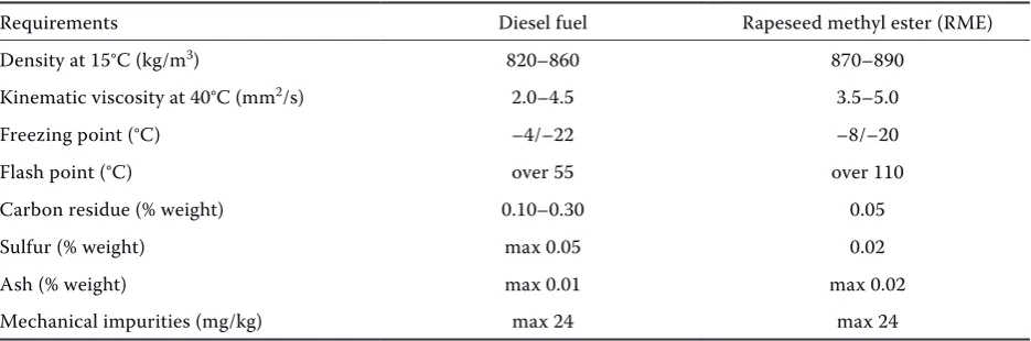
Although rapeseed methyl ester (RME) differs chemically from petroleum products, its density, viscosity, calorific value and process of combus-tion are very close to diesel fuel (Li et al. 2006; Vančurová 2008). Table 1 lists the specific tech-nical requirements for diesel oil and RME (ČSN EN 14214:2004; ČSN EN 590:2010).
The literature says that in terms of power param-eters the maximum value will decrease by about 3–5% for the fuel with 31% content of RME. The fuel consumption will slightly increase by approxi-mately 7% for this fuel (Basha et al. 2009). It is also necessary to take into account that RME evapo-rates worse than diesel and so it can enter the oil filling of the engine (Holas 1996).
Characteristics of internal combustion engines are used as proof of the properties of the engine (Bauer et al. 2006). They are presented in graphic form and the measured values are often corrected to standard conditions according to applicable regula-tions or standards. The characteristic of the com-bustion engine means the relationship between the main engine operating parameters such as engine speed, torque (or mean effective pressure), power, specific fuel consumption, exhaust temperature, pressure of filling air etc. The basic characteristics of internal combustion engine are:
Speed (RPM) – engine speed is the independent variable, the characteristic is measured at a con-stant setting of the engine speed governor;
Load – the engine load which is represented by the mean effective pressure engine torque is the in-dependent variable, this characteristic is measured at constant engine speed;
Engine map – this map shows the curves of con-stant power, concon-stant specific fuel consumption and constant curves of the other quantities de-pending on the engine speed and its torque.
Any change in single characteristic indicates change in engine settings or degradation of the technical condition of the engine which is affect-ed by the operational wear (Müller et al. 2009). Emerging fault can be detected by checking these characteristics and so the maintenance or repair can be done timely. Engine characteristics can be measured on a roller dynamometer, on a dy-namometer connected to rear power take-off or using dynamic measuring methods (Hromádko et al. 2007). Different driving cycles can be simulated based on mathematical modelling of these char-acteristics (Jílek et al. 2008; Brožová, Růžička 2009; Kubín, Pexa 2010; Pexa, Kubín 2010).
Tractor Zetor Forterra 8641 which is located in the laboratories of the Department for Quality and Dependability of Machines was used to verify the effect of RME share in fuel on engine map of an internal combustion engine. The engine of the trac-tor had less than 100 worked hours and laboratrac-tory measurements represent most of its previous work. Several ratios of diesel fuel which is available on the common fuel station and RME was selected as fuel. The ratios of diesel and RME changed from pure diesel to pure RME as follows:
– fuel No. 1: 100% diesel fuel,
– fuel No. 2: 85% diesel fuel and 15% RME, – fuel No. 3: 70% diesel fuel and 30% RME, – fuel No. 4: 55% diesel fuel and 45% RME, – fuel No. 5: 100% RME.
The use of diesel fuel from the common fuel sta-tion was chosen mainly because of its easy acces-sibility. In terms of practice there is a significant fact that the majority of agricultural tractors use this fuel. Diesel fuel supplied to the network of fuel stations (ČSN EN 590:2010) includes manda-tory share of biofuels (RME) in accordance with the EU legislation. This represents a partial complica-tion for measuring the effect of RME share in fuel on the engine map of tractor engine. In the Czech Republic there is currently prescribed 6% share of biofuel in diesel supplied in the market for a longer period of time (valid from 1. 6. 2010). The amount of biofuel in diesel shall not exceed 7%. Therefore the share of biofuels in diesel fuel at the fuel sta-tion is not clearly defined and fluctuates around 6%. It was necessary to analyse all of test fuels to determine the actual percentage of RME in each of them. Founded proportion of RME in test fuels is as follows:
– fuel No. 1: 5.5% RME (diesel from fuel station), – fuel No. 2: 19.7% RME,
– fuel No. 3: 33.9% RME, – fuel No. 4: 48.0% RME, – fuel No. 5: 100.0% RME.
MAtEriAl And MEthods
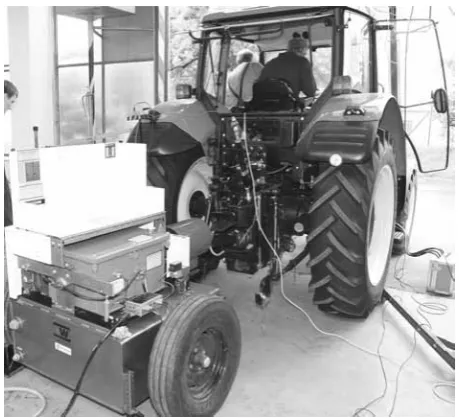
Measuring devices were gradually attached to the measured tractor Zetor Forterra 8641 (Zetor Trac-tors a.s., Brno, Czech Republic) (Table 2). Hydrau-lic dynamometer (Fig. 1) was connected to the rear power take-off of the tractor. Basic parameters of the dynamometer AW NEB 400 (AW Dynamom-eter Inc., North Pontiac, USA) which was used are shown in Table 3. The fuel box which contains two flow meters Macnaught MSeries M2ASP-1R (Mac-Table 1. Selected technical requirements for diesel and rapeseed methyl ester (ČSN EN 590, ČSN EN 14214)
Requirements Diesel fuel Rapeseed methyl ester (RME)
Density at 15°C (kg/m3) 820–860 870–890
Kinematic viscosity at 40°C (mm2/s) 2.0–4.5 3.5–5.0
Freezing point (°C) –4/–22 –8/–20
Flash point (°C) over 55 over 110
Carbon residue (% weight) 0.10–0.30 0.05
Sulfur (% weight) max 0.05 0.02
Ash (% weight) max 0.01 max 0.02
[image:2.595.64.532.101.256.2]naught Pty, Ltd., Turrella, Australia) was used to measure fuel consumption of the engine. The first flow meter measures the amount of fuel supplied to the engine and the second flow meter measures the amount of fuel that returns to the tank. The main
parameters of the flow meter M2ASP-1R are shown in Table 4. The fuel tank of the tractor was com-pletely disconnected during the measurement and an auxiliary tank for currently tested fuel which has 30 l capacity was used instead of it. No other modi-fication of the tractor fuel system was performed. The following sensors were also connected: air temperature and pressure sensor, engine oil tem-perature sensor and fuel temtem-perature sensor.
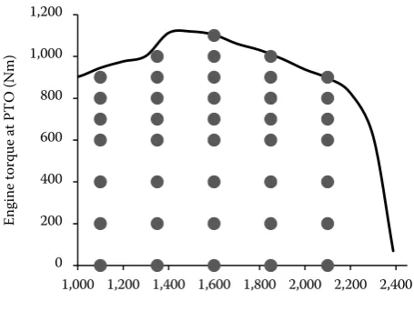
[image:3.595.62.292.82.291.2]Once the tractor was ready for testing the test fuel was prepared (diesel and RME). The mixtures of 100/0, 85/15, 70/30, 55/45 and 0/100 (diesel from a fuel station/RME) were mixed. A sample of diesel (purchased at fuel station) was taken for laboratory analysis which showed 5.5% share of RME in this fuel. The flushing of the tank and fuel system was re-alized after each change of fuel mixture to ensure the removal of any previous fuel mixture (mixed proportions of pump overflow were captured and completely excluded from measurements). The tractor engine was warmed up after filling the tank with selected fuel to reach its operating tempera-ture. The rated speed characteristic (governor of engine speed at maximal position) of the engine was measured after heating the engine (Fig. 2). This characteristic was used to determine the appro-priate measuring point for creating of the engine map (Fig. 3). The measurement points (about 35) Table 2. Basic technical parameters of the engine Zetor 1204
in Zetor Forterra 8641 tractor (manufacturer’s data accord-ing to ECE R24)
Parameter Value
Rated power (kW) 60
Rated speed (1/min) 2,200
Max. torque (Nm) 351
Specific fuel consumption at rated
power (g/kWh) 253
Max. speed (1/min) 2,460
[image:3.595.304.533.116.181.2]Idling speed (1/min) 750
Table 3. Basic technical parameters of the dynamometer AW NEB 400
Parameter Value
Max. torque at power take-off (Nm) 2,850
Max. power take-off speed (1/min) 3,200
Max. braking power (kW) 343
Max. braking power at power
take-off speed 540 1/min (kW) 149
Max. braking power at power
take-off speed 1,000 1/min (kW) 298
[image:3.595.63.291.385.503.2]Error in measurement (%) 2
Table 4. Basic technical parameters of the flow meter M2ASP-1R
Parameter Value
Max. flow rate (l/h) 500
Resolution (pulses/l) 400
[image:3.595.305.533.568.728.2]Error in measurement (%) 1
Fig. 1. Tractor Zetor Forterra 8641 with attached dy-namometer AW NEB 400
0 10 20 30 40 50 60
0 50 100 150 200 250 300 350
1,100 1,300 1,500 1,700 1,900 2,100 2,300
Eng
ine
pow
er
(k
W
)
Eng
ine
tor
que
(N
m
)
Engine speed (1/min)
Engine torque (Nm) Engine power (kW)
[image:3.595.63.292.630.756.2]is created (1,681 points). SPLINE function is used in further work with this matrix. This function which uses interpolation from points of the matrix allows determining the value of a monitored variable at any engine operating point.
[image:4.595.63.291.83.254.2]rEsults
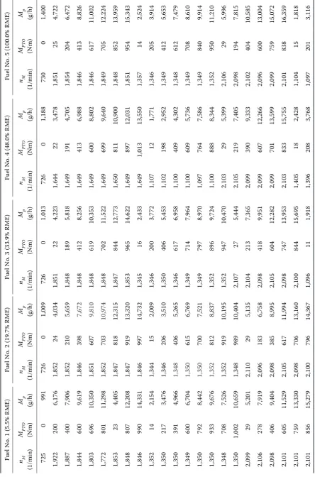
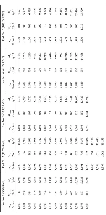
Table 5 shows all measured points and meas-ured fuel consumption for each of test fuels. The function REGRESS together with the functions INTERP (1) interleave the measured points in fuel consumption PlochaZ with pre preset cubic poly-nomial set cubic polypoly-nomial. PlochaZ is in coor-dinates PlochaXY (om and TM are coordinates of engine speed and torque). The result is a continu-ous surface Plocha(om, TM). A square matrix of 41 × 41 (1,681 points) is created from this surface for further processing.
(1)
where:
PlochaXY – matrix giving the coordinates of engine speed and torque om and TM PlochaZ – single column matrix of data of the
processed quantity (e.g. fuel con-sumption) (g/h)
3 – degree of the polynomial (optional)
Plocha(om,TM) – continuous surface of processed quantity (g/h)
om – coordinates of engine speed (1/min)
TM – coordinates of engine torque (Nm)
The matrix of 1,681 points is interleaved using the SPLINE function (2) in the further processing. The SPLINE function interleaves the surface exact-ly in the points which are defined in 41 × 41 matrix.
(2)
where:
Plocha – matrix of measured quantity in 1,681 points (g/h)
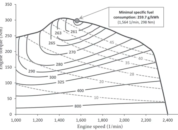
The procedure of making surfaces (1, 2) is applied to all of test fuels and the results are shown in form of engine maps in Figs 4–8. The point where the en-are defined so that most of them en-are in the
work-ing area of the engine. Definwork-ing of these points was followed by their measurement. After turning the power take-off on the dynamometer and the gover-nor of engine speed were set so that the engine has stabilized in the desired measuring point. Engine speed, torque, fuel consumption and other moni-tored quantities were registered after stabilization of the engine. Engine power was then calculated from engine speed and its torque.
The dependence of density on temperature was found for each of test fuels. The gravimetric and specific fuel consumption were calculated from measured values using this dependence. Values of torque and shaft speed which were measured on power take-off were converted to engine values us-ing the appropriate gear ratio (3.543). The power losses in transmission between the engine and power take-off which can be regarded as constant are not significant for comparison of the effect of fuel type on engine map. Therefore these losses are not considered in evaluation of the measurement. So the calculated values of specific fuel consump-tion correspond to engine power on the power take-off.
Measured values were then processed using func-tions of the MathCAD software (PTC Corporate Headquarters, Needham, USA) into continuous sur-faces. REGRESS and INTERP functions were used to create continuous surfaces. REGRESS function allows selecting a suitable degree of the polynomial. Quadratic or cubic polynomials are sufficient for fuel consumption. Surfaces thus created are stored in a file in a text format, where a matrix of 41 × 41 points Fig. 3. An example of defined measurement points – 85/15 (diesel from fuel station/RME)
=
=
TM om PlochaZ PlochaXY
R TM
om Plocha
PlochaZ PlochaXY
R
, ,
, interp ) , (
) 3 , ,
( regress
=
TM om Plocha PlochaXY Plocha
PlochXY TM
om
Plocha( , ) interp cspline( , ), , ,
=
TM om Plocha PlochaXY Plocha
PlochXY TM
om
Plocha( , ) interp cspline( , ), , ,
0 200 400 600 800 1,000 1,200
1,000 1,200 1,400 1,600 1,800 2,000 2,200 2,400
Eng
ine
torq
ue
at
PT
O
(N
m)
Ta
ble 5. M
ea
sur
ed p
oin
ts and me
asur ed f ue l c onsum ption f or e ac
h of t
est f
ue
ls
Fue
l No. 1 (5.5% R
ME)
Fue
l No. 2 (19.7% R
ME)
Fue
l No. 3 (33.9% R
ME)
Fue
l No. 4 (48.0% R
ME)
Fue
l No. 5 (100.0% R
ME) nM (1/min) MPT O (Nm)
Mp (g/h)
nM
(1/min)
MPT
O
(Nm)
Mp (g/h)
nM
(1/min)
MPT
O
(Nm)
Mp (g/h)
nM
(1/min)
MPT
O
(Nm)
Mp (g/h)
nM
(1/min)
MPT
O
(Nm)
Mp (g/h)
Fue
l No. 1 (5.5% R
ME)
Fue
l No. 2 (19.7% R
ME)
Fue
l No. 3 (33.9% R
ME)
Fue
l No. 4 (48.0% R
ME)
Fue
l No. 5 (100.0% R
ME) nM (1/min) MPT O (Nm)
Mp (g/h)
nM
(1/min)
MPT
O
(Nm)
Mp (g/h)
nM
(1/min)
MPT
O
(Nm)
Mp (g/h)
nM
(1/min)
MPT
O
(Nm)
Mp (g/h)
nM
(1/min)
MPT
O
(Nm)
Mp (g/h)
1,100 12 1,896 2,100 879 15,591 1,101 198 2,753 1,402 395 5,443 1,100 401 4,591 1,101 230 2,635 1,107 16 1,912 1,101 405 4,925 1,402 608 7,285 1,100 600 5,982 1,102 388 3,871 1,100 202 2,991 1,102 607 5,760 1,396 708 8,290 1,100 703 6,935 1,102 590 5,353 1,101 398 3,988 1,101 708 6,768 1,398 806 9,462 1,098 807 7,976 1,100 680 6,341 1,098 605 5,737 1,103 804 7,436 1,400 909 10,291 1,103 909 9,276 1,098 796 7,247 1,105 704 6,408 1,102 902 8,439 1,400 947 10,960 1,594 19 3,373 1,617 22 3,135 1,098 824 7,490 1,604 22 3,175 1,853 27 4,016 1,603 192 4,930 1,601 215 4,616 1,104 924 8,488 1,605 207 4,762 1,845 205 6,034 1,598 397 7,178 1,600 389 6,341 1,603 31 2,993 1,599 397 6,684 1,846 403 7,961 1,603 608 9,254 1,604 594 8,071 1,596 210 4,479 1,601 606 8,689 1,847 617 10,216 1,599 711 10,378 1,599 697 9,141 1,598 401 6,392 1,598 706 9,441 1,849 701 11,295 1,597 806 11,061 1,598 803 10,039 1,603 612 8,336 1,601 816 10,695 1,849 820 12,957 1,598 906 12,444 1,598 897 10,935 1,601 716 9,373 1,598 952 12,449 1,849 939 14,438 1,600 1,019 13,729 1,603 1,055 12,990 1,598 812 10,326 1,596 1,031 12,940 1,600 898 11,188 1,598 1,011 12,483 1,599 1,062 13,155 nM – eng ine sp ee d (1/min); MPT O – eng ine t or que me asur
ed on p
[image:6.595.79.424.70.767.2]ower t ak e-of f (Nm); Mp – g ra vime tr ic hour ly f ue l c onsum ption ( g/h) Ta
ble 5. t
800 400 325 300 290
280 270 265
263 261
10 20
28
35 40
45
0 50 100 150 200 250 300 350
1,000 1,200 1,400 1,600 1,800 2,000 2,200 2,400
Eng
ine
to
rque
(N
m
)
Engine speed (1/min)
Minimal specific fuel consumption: 259.7 g/kWh
(1,564 1/min, 298 Nm)
solid lines = isolines of specific consumption (g/kWh) dashed lines = isolines of power (kW)
800 500 400
350 325 300 285
275
270 267
265 264 263
10 20
28 35
40 45 50
53
0 50 100 150 200 250 300 350
1,000 1,200 1,400 1,600 1,800 2,000 2,200 2,400
Eng
ine
to
rque
(N
m
)
Engine speed (1/min)
Minimal specific fuel consumption: 262.6 g/kWh
(1,612 1/min, 311 Nm)
[image:7.595.68.354.83.291.2]solid lines = isolines of specific consumption (g/kWh) dashed lines = isolines of power (kW)
[image:7.595.65.367.325.754.2]Fig. 4. Engine map for fuel No. 1 (5.5% RME)
Fig. 5. Engine map for fuel No. 2 (19.7% RME)
Fig. 6. Engine map for fuel No. 3 (33.9% RME)
Engine speed (1/min)
Engine speed (1/min)
Engine speed (1/min)
Eng
ine t
or
que (Nm)
Eng
ine t
or
que (Nm)
Eng
ine t
or
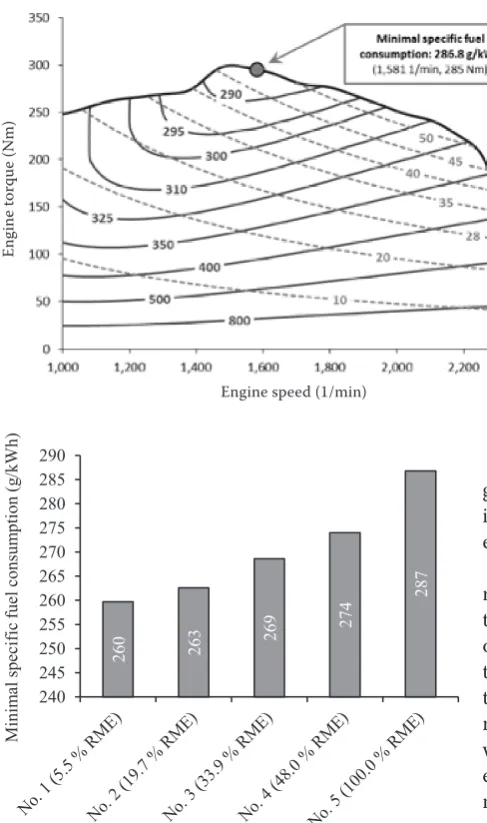
Fig. 9. Change of minimum specific fuel consumption on the power take-off with increasing proportion of RME
[image:8.595.66.292.500.722.2]Fig. 7. Engine map for fuel No. 4 (48.0% RME)
Fig. 8. Engine map for fuel No. 5 (100.0% RME)
260 263 269
274
287
240 245 250 255 260 265 270 275 280 285 290
M
ini
m
al
spe
ci
fic
fue
l c
ons
um
pt
ion
(g
/k
W
h)
Fuel type
gine reaches minimum specific fuel consumption is marked in each map. There are also mentioned engine speed and torque of this point.
The increase of RME proportion in diesel fuel is reflected by increasing the specific fuel consump-tion. The lowest minimum specific fuel consumption of 259.7 g/kWh was achieved on diesel, which con-tained only the proportion of RME which is given by the legislation (5.5%). On the other hand, the highest minimum specific fuel consumption of 286.8 g/kWh was achieved at a pure RME (Fig. 9). The section of engine map with lowest specific fuel consumption re-mained maintained at all measured fuels. The engine speed is in this case in the range between 1,530 and 1,630 1/minand the torque reaches values near to its maximum at this engine speed.
Engine speed (1/min)
Eng
ine t
or
que (Nm)
Eng
ine t
or
que (Nm)
discussion And conclusion
The use of RME in the internal combustion en-gine of agricultural tractors is accompanied with a reduction of power parameters and an increase of specific fuel consumption. It is stated that the drop in power parameters is 3–5% and the increase in fuel consumption is around 7% for the diesel with 31% of RME (Holas 1996, Vančurová 2008).
The share of RME mainly reflects in the increased specific fuel consumption as it can be seen on the presented engine maps. The minimum specific fuel consumption of 259.7 g/kWh (power take-off) was achieved when the engine of the tractor Zetor For-terra 8641 operates on diesel from common fuel station (5.5% RME). When the engine was operat-ing on pure RME the reached minimum specific fuel consumption was 286.8 g/kWh. This represents an increase of about 10%. The operating area of the en-gine where the minimum specific fuel consumption is achieved remains unchanged. The engine speed is 1,530–1,630 1/min in this area and the torque is very close to its maximum at this speed (Figs 4–8).
The increase in specific fuel consumption is mainly associated with a reduction in tractor engine power parameters. The maximum torque of 318 Nm which was reached for the diesel from fuel station decreased to 299 Nm when the engine operates on pure RME. This means that the reduction is approximately 6%.
The choice of operating modes of the engine re-mains unchanged and so it is possible to operate the tractor in the same way. The advantage of using RME is also the ability to use it without any technical modi-fication of the engine (most of new engines is ready for using RME). However, it is necessary to take into account the properties of RME and it is also impor-tant to take care of fuel system, particularly with re-gard to the removal of water and other sediments.
references
Basha S.A., Gopal K.R., Jebaraj S., 2009. A review on biodiesel production, combustion, emissions and
perfor-mance. Renewable and Sustainable Energy Reviews, 13:
1628–1634.
Bauer F., Sedlák P., Šmerda T., 2006. Traktory (Tractors). Prague, Profi Press.
Brožová H., Růžička M., 2009. Quantitative analysis of environmental impact of transport projects. Scientia Ag-riculturae Bohemica, 40: 216–225.
ČSN EN 590, 2010. Motorová paliva – Motorové nafty – Technické požadavky a metody zkoušení (Automotive Fuels – Diesel – Requirements and Test Methods). ČSN EN 14214, 2004. Motorová paliva – Methyl estery
mastných kyselin (FAME), palivo pro vznětové motory – Technické požadavky a metody zkoušení (Automotive Fuels – Fatty Acid Methyl Esters (FAME) for Diesel Engi-nes – Requirements and Test Methods).
Holas J., 1996. Současný stav výroby a užití bionafty v Čes-ké Republice (Current status of production and use of biodiesel in the Czech Republic). In: Proceedings of 13th Evaluation Seminar “The System of Production of Rape“. November 26–28, 1996. Hluk, 162–168.
Hromádko J., Hromádko J., Kadleček B., 2007. Problems of power parameters measurement of constant-speed engines with small cylinder volume by acceleration method. Eksploatac-ja i Niezawodność – Maintenance and Reliability, 33: 19–22. Jílek L., Pražan R., Podpěra V., Gerndtová I., 2008.
The effect of the tractor engine rated power on diesel fuel consumption during material transport. Research in Ag-ricultural Engineering, 54: 1–8.
Kubín K., Pexa M., 2010. Model jízdy traktorové dopravní soupravy – Energetické a exploatační ukazatele (Modeling of Tractor Transport Set – Energy and Exploitation Indica-tors). Agritech Science, 4: 1–8.
Li Y.X., Mclaughlin N.B., Patterson B.S., Burtt S.D., 2006. Fuel efficiency and exhaust emissions for biodiesel blends in an agricultural tractor. Canadian Biosystems Engineering, 48: 2.15–2.22.
Müller M., Chotěborský R., Hrabě P., 2009. Degradation processes influencing bonded joints. Research in Agricul-tural Engineering, 55: 29–34.
Pexa M., Kubín K., 2010. Modeling of 8-mode test proce-dure for Zetor Forterra 8641 tractor. Scientia Agriculturae Bohemica, 41: 149–155.
Vančurová P., 2008. Podmínky konkurenceschopnosti výro-by bionafty v České republice (Conditions of Competitive-ness of Biodiesel Production in the Czech Republic). [Ph.D. Thesis.] Prague, Czech University Life Sciences Prague.
Received for publication June 6, 2011 Accepted after corrections July 21, 2011
Corresponding author:
Ing. Martin Pexa, Ph.D., Czech University of Life Sciences Prague, Faculty of Engineering,