© 2019, IRJET | Impact Factor value: 7.211 | ISO 9001:2008 Certified Journal
| Page
1398
Hybrid PSODE Algorithm Embedded with FPGA for Speed Control of
BLDC Motor
Dr.T.V. Mahendiran
1, Dr. Thangam Palaniswamy
21
Assistant Professor, Department of Electrical and Computer Engineering, Jeddah,
King Abdulaziz University, Saudi Arabia.
2
Associate Professor, Department of Electrical and Computer Engineering, Jeddah,
King Abdulaziz University, Saudi Arabia.
---***---Abstract –
In this paper, speed control of BLDC motor isdescribed. The speed control of BLDC motor is achieved by implementing soft computing algorithms in FPGA based hardware setup. This work concentrates to implement the four controllers to control the speed of BLDC motor namely
Fuzzy Logic Controller, Fuzzy PI controller, Particle Swarm
Optimization (PSO) fuzzy PI controller and hybrid PSODE based fuzzy PI controller. The performance of all the controller are analyzed under the varying load at constant speed of motor and varying speed and load of the motor simultaneously. Finally, the experimental results are discussed and compared to identify the better controller for efficient speed control.
Key Words:Differential Evolution (DE), Particle Swarm Optimization (PSO), PI Controller, Fuzzy Logic Controller, FPGA, Speed Control, BLDC.
1. INTRODUCTION
In this world time is very crucial. Most of the research is concentrating to get the output with minimum time. Especially in the industries are giving importance very much to accuracy of time to complete the task. Almost all the manufacturing units in the world depend on electric motors for their production. In automation Industries the electrical motors play important role. Future world will be automated for every process. At this condition, every second is very important to obtain the desired task. An electrical motor consumes only less energy with a good speed control method.
In this work focused the BLDC motor Speed Control.Now a day’s usage of BLDC motors is increased in industrial applications due to its better torque verses Speed characteristics, high speed range, high efficiency, dynamic response and noiseless operation. Also, it has long operating life due to less electrical and friction losses.
BLDC is more popular in, Industrial Engineering, Transport Industry, Automation Engineering, Consumer Electronics. With help of BLDC, the industries are improving quality and productivity of the product.
In this research, excellent speed control of BLDC motor is achieved by new developed algorithm based on combination of Particle Swarm Optimization (PSO) and Differential Evolution (DE). Speed control of BLDC motor is tested under the condition of varying speed at constant load and varying load and speed at same time. The result of the above algorithm is compared with the result of Fuzzy Logic Controller, Fuzzy PI Controller and Particle Swarm Optimization (PSO) based Fuzzy PI Controller which are already developed for the same application, under the same conditions. FPGA based setup has been developed for implementing the above four controllers for speed control of BLDC motor.
Due to the advance’s concepts in power electronic, power electronic devices be a very important part in the control of electrical equipment’s and machinery [3]. The power electronics devices are of utmost importance in the conversion of electrical energy above billions of kilowatts in an efficient, clean, compact and robust manner for convenient utilization [7] [11]. In this work, power electronic drives are used for speed control of electric motors. Gate current, which is used to control the input voltage of the motors, is controlled by optimizing the controller parameters. Based on the input voltage control, the speeds of the motors are controlled as per the reference speed.
2. EARLIER WORK CARRIED OUT IN SPEED
CONTROL OF BLDC
© 2019, IRJET | Impact Factor value: 7.211 | ISO 9001:2008 Certified Journal
| Page
1399
3. CONTROLLERS
Analog control has been verified to be the best control mechanism for any industrial drive. But, the classical controllers namely PID (Proportional Integral Derivative) controllers need exact mathematical model of the systems and are very sensitive to parameter variations [1]. Therefore, the use of classical controllers does not meet the requirements for better performance.
The development of Artificial Intelligence (AI) created the new era in the field of industrial drives [8] [15]. Various AI based controls have shown an excellent performance in constant speed variable torque or constant torque variable speed drive applications [9][17]. So, the performance of Artificial Intelligence (AI) based controllers urged power system and power electronic engineers to replace conventional speed control circuits with intelligent speed controllers. In this research, artificial intelligence based Fuzzy Logic Controller (FLC) is used. FLC rule base is optimized to improve performance by applying the following algorithm, for achieve better speed control:
Particle Swarm Optimization and
Hybrid algorithm of Particle Swarm Optimization and Differential Evolution
FLCs are smart control systems characterized by a set of linguistic statements based on specialist knowledge. Fuzzy Logic Controllers have been broadly used for imprecise, non-linear and complex systems [12]. A simple FLC consists of four major elements: a fuzzifier, a rule base, a fuzzy inference engine and a defuzzifier [14][17]. The fuzzifier converts real system variables into fuzzy variables. The inference unit provides the necessary connection between the controller input and output fuzzy sets. The rule base expressed in the form of If-Then rules is used by the inference unit. The defuzzifier takes the results of fuzzy reasoning and produces a new real control action [5].
Particle Swarm Optimization (PSO) is an algorithm for finding optimal regions of complex search space through interaction of individuals in a population of particles. PSO algorithm, originally introduced in terms of social and cognitive behavior by Kennedy and Eberhart (1995) [6] has been proven to be a powerful competitor to other evolutionary algorithms such as genetic algorithms [2]. PSO is a population based stochastic optimization technique, well adapted to the optimization of nonlinear functions in multidimensional space. PSO has received significant interest from researchers in different research areas and has been applied to several real-world problems. PSO algorithm simulates social behavior among individuals (particles) flying through multidimensional search space, each particle representing a single intersection of all search dimensions.
The particles evaluate their positions relative to a global fitness value, at every iteration. Companion particles share memories of their best positions and then use those memories to adjust their own velocities and positions. At each generation, the velocity of each particle is updated, being pulled in the direction of its own previous best solution and the best of all positions (global). Particle swarm optimization became a popular algorithm due to its simplicity and usage of few variables [17]. It has been successfully implemented in many areas such as neural network, fuzzy logic, control of power electronics drives, image processing and system identification in bio mechanics.
Differential Evolution (DE) is one of the global optimization algorithms proposed by Price [16] which is applied for speed control applications. It is a new floating point encoded evolutionary algorithm for global optimization, owing to a special kind of differential operator, which was invoked to create new offspring from the parent chromosomes instead of classical crossover or mutation. Easy methods of implementation and negligible parameter tuning made the algorithm popular very soon. Several enhancements were continuously developed from the DE for further optimization [4] [13].
FPGAs are reprogrammable silicon chips invented by Ross Freeman in 1985. FPGA is an integrated circuit that contains many identical logic cells, interconnected by a matrix of wires and reprogrammable switches. This interconnection of logic cells forms the basic building block for logic circuits. A user’s design is implemented by specifying the simple logic function for each cell and selectively closing the switches in the interconnect matrix. Each logic cell combines a few binary inputs to one or two outputs according to a Boolean logic function specified in the user program. FPGAs provide good hardware time, speed, reliability and flexibility. They are widely used in motor control applications due to their robustness and customizability.
3.1
ALGORITHM OF PSODEAlgorithm of PSODE is described below:
Step 1 : Define fitness function
Step 2 : Initialize the particles of the population according to the limits. Initialize parameters Wmax, Wmin, C1, C2 and itermax.
Step 3 : Generate the initial population of N particles with random positions and velocities
Step 4 : Calculate the fitness and evaluate the fitness values of current particle using the objective function of MSE.
2
© 2019, IRJET | Impact Factor value: 7.211 | ISO 9001:2008 Certified Journal
| Page
1400
Step 5 : Compare the fitness value of each particle with itspbest. If the current value is better than pbest, then set pbest value to the current value.
Step 6 : Compare the fitness value of each particle with its gbest. If the current value is better than gbest, then set gbest value to the current value.
Step 7 : The member velocity V of everyone in the population is updated according to the velocity update equation,
Vi(t+1) = w x Vi(t)+ c1 x r1 x (pbesti-xi(t)) + c2 x r2x (gbest – xi(t)) (2)
Step 8 : The member velocity components constraint occurring in the limits are checked. If the calculated velocity is out of boundary or closely to zero [Velocity < rand (0,1)], a mutation operator of the DE is activated, recalculate the velocity of this particle by using mutation operator as Vi(t+1) = F x ((xk(t)- xi(t))- (xq(t)- xi(t))) (3)
Step 8 : The position of each individual is modified according to the position update equation, given in equation,
New position = old position + updated velocity (4) Step 9 : If the number of iterations reaches the maximum, then go to Step 10. Otherwise, go to Step 4.
Step 8 : The particle that generates the latest gbest is the solution of the problem.
Step 9 : Stop.
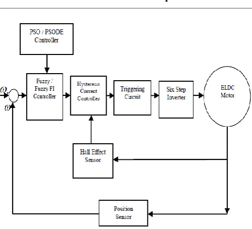
4. BLOCK DIAGRAM FOR SPEED CONTROL OF BLDC MOTOR
[image:3.595.309.559.75.302.2]BLDC motor speed is obtained through calculating the rotor position. The derivative of rotor position gives the speed of the motor. The speed error is calculated from the difference between actual speed and reference speed. Speed error and change in speed error are given as inputs to the controllers. The controllers give the reference current as output, which is fed as input to the current controller. The current controller generates the gate current to the six- step inverter based on the comparison between the actual phase current of motor which is sensed by the hall sensor and the reference current from controller. The input voltage of the BLDC motor is controlled by firing angle of the inverter.
Fig-1 Block Diagram for Speed Control of BLDC Motor
5. RESULTS AND DISCUSSION:
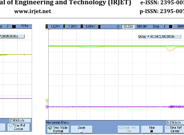
5.1 Varying Load at Constant Speed
In this condition, the load is suddenly changed at constant speed. The performances of every controller is evaluated at this situation. When load is varied, the speed of the motor is kept as constant during this criterion. At start, the motor is run without load. Hence, the motor attains the reference speed and remains in that speed. When the load is changed from no load to loaded condition, BLDC motor speed is changed with decreases and is back to the reference speed, when motor is unloaded. Based on the speed response graphs shown in Fig 2 to Fig 6, the results are tabulated in Table 1. From the analysis of the values in Table 1, the settling time of speed response of the BLDC motor with PSODE fuzzy PI controller gives better than other controllers.
[image:3.595.308.558.571.721.2]© 2019, IRJET | Impact Factor value: 7.211 | ISO 9001:2008 Certified Journal
| Page
1401
Fig-3 Hardware graph of Fuzzy Controller under [image:4.595.233.549.52.284.2]Change in Load at constant Speed Condition
Fig-4 Hardware graph of Fuzzy PI Controller under Change in Load at constant Speed Condition
[image:4.595.36.288.324.480.2]Fig-5 Hardware graph of PSO Fuzzy PI Controller under Change in Load at constant Speed Condition
Fig-6 Hardware graph of PSODE Fuzzy PI Controller under Change in Load at constant Speed Condition
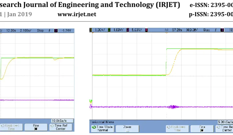
5.2 Varying Speed and Load Simultaneously
Under this condition, both the speed and load of the motor are changed. In this research, two cases are considered:
i) increase in speed with no load
[image:4.595.307.558.485.662.2]ii) increase in speed and increases in load. Based on the speed response graphs shown in
Fig 7 to 11, the results are summarized in Table 1. From the performance comparison of the controllers, the hybrid PSODE gives better results than other controllers
.
[image:4.595.38.290.525.709.2]© 2019, IRJET | Impact Factor value: 7.211 | ISO 9001:2008 Certified Journal
| Page
1402
Fig-8 Hardware graph of Fuzzy Controller underChange in Speed and Load simultaneously
[image:5.595.37.299.53.265.2]Fig-9 Hardware graph of Fuzzy PI Controller under Change in Speed and Load simultaneously
[image:5.595.42.304.311.481.2]Fig-10 Hardware graph of Fuzzy PSO PI Controller under Change in Speed and Load simultaneously
Fig-11 Hardware graph of PSODE Fuzzy PI Controller under Change in Speed and Load simultaneously
Table -1: Comparative Analysis of settling time (in seconds) of all controllers under all two conditions for
speed control of BLDC motor
6. CONCLUSION
In this paper discussed about the Speed Control of BLDC Motor by five controllers namely, Conventional PI Controller, Fuzzy Controller, Fuzzy PI Controller, PSO fuzzy PI Controller and PSODE fuzzy PI Controller. All the controller algorithms are implemented in FPGA based hardware setup. From the result and discussion, the performance of PS0DE based speed controller was efficient than other controllers under the all conditions.
REFERENCES
[1] Ahmed, F.I., El-Tobshy, A.M., Mahfouz, A.A. and
Ibrahim, M.M.S. “P-I and I-P controllers in a closed loop for DC motor drives”, Proceeding of the Power Conversion Conf. 1997-Nagaoka, IEEE Xplore, pp. 613-618, 1997.
[2] Del Valle, Y., Venayagamoorthy, G.K., Mohagheghi, S.,
Hernandez, J.C. and Harley, R.G. “Particle swarm optimization: Basic concepts, variants and Conditions PI Fuzzy Fuzzy PI Fuzzy PSO
PI
PSO DE Fuzzy
PI
Varying Load at Constant Speed
At load
applied 3.6 3 1.56 1.2 1
At load
released 4 3 1.56 1.2 1
Varying Speed and Load at Simultaneously
Sudden Change
1 6 1.68 1.6 1.56 0.98
Sudden Change
[image:5.595.177.555.338.498.2] [image:5.595.39.285.525.705.2]© 2019, IRJET | Impact Factor value: 7.211 | ISO 9001:2008 Certified Journal
| Page
1403
applications in power systems”, IEEE Trans. Evol.Comput., Vol. 12, pp. 71-195, 2008.
[3] Dubey, G.K. Power Semiconductor Controlled
Drives, Prentice Hall, New Jersey, 1989.
[4] Fan, H.Y., Lampinen, J. “A Trigonometric Mutation
Operation to Differential Evolution”, International Journal of Global Optimization, Vol. 27, No. 1, pp. 105-129, 2003.
[5] Jahir Abbas Mullick,” Fuzzy Controller for Speed
Control of BLDC motor using MATLAB”, International Research Journal of Engineering and Technology, Vol.4 pp.1270-1274,.2017
[6] Kennedy, J., Eberhart, R.C. and Shi, Y. Swarm
Intelligence, Morgan Kaufmann Publishers, 2001.
[7] Krishnan, R. Electric Motor Drives: Modeling,
Analysis and Control, Pearson Education, New Delhi, 2001.
[8] Krohling, R.A., Jaschek, H. and Rey, J.P. “Designing
PI/PID controller for a motion control system based on genetic algorithms”, Proceedings of the IEEE International Symposium on Intelligent Control, Istanbul, IEEE Xplore, pp. 125-130, 1997.
[9] Kukolj, D., Kulic, F. and Levi, E. “Design of the speed
controller for sensor less electric drives based on AI techniques: a comparative study”, Artificial Intell. Eng., Vol. 14, pp. 65-17, 2000.
[10] Mahendiran.T.V, Thanushkodi. K ,“A new improved
algorithm for speed control of Brushless DC motor”, International Conference on Current Trends in Engineering and Technology (ICCTET) in Proc.,IEEE Xplore, pp 46-51, 2013
[11] Murphy, J.M.D. and Turnbull, F.G. Power Electronic
Control of AC Motors, Pergamon Press, Oxford, 1988.
[12] Narmadha, T.V. and Thyagarajan, T. “Fuzzy Logic
based position-sensorless speed control of multi level inverter fed PMBLDC drive”, J. Advances in Inf. Technol., Vol. 1, pp. 52-58, 2010.
[13] Price, K., Storn, R. and Lampinen, J. Differential
Evolution – A Practical Approach to Global Optimization, Springer, Berlin Heidelberg New York, 2005.
[14] Rubi batham, Rameshwar Singh ,”Speed Control of
Brushless DC Motor Using Different Intelligence Schemes”, International Research Journal of Engineering and Technology, Vol.4 pp.654-659.2017
[15] Sousa, G.C.D. and Bose, B.K. “A Fuzzy Set Theory
Based Control for Phase-Controller Converter DC Machine Drive”, IEEE Trans. Indus. Appl., Vol. 30, pp. 34-44, 1994.
[16] Storn, R. and Price, K. “Differential Evolution – A
Simple and Efficient Heuristic for Global Optimization Over Continuous Spaces”, Journal of Global Optimization, Vol. 1, No. 4, pp. 341-359, 1997.
[17] Mahendiran, T.V., Thanushkodi, K. and Thangam, P.