© 2019, IRJET | Impact Factor value: 7.211 | ISO 9001:2008 Certified Journal | Page 848
CFD ANALYSIS OF SPARE WHEEL RUNNER FOR USING EASY CAR
PARKING
1
R.Satheesh kumar,
2M.Balamurugan,
3K.Chandrakasan,
4S.Gunasheelan,
5K.Hithayathulla
1
Assistant Professor, Department of Mechanical Engineering, Dhanalakshmi Srinivasan Institute of Technology,
Tamil Nadu, India.
2,3,4,5
UG Sudents, Department of Mechanical Engineering, Dhanalakshmi Srinivasan Institute of Technology,
Tamil Nadu, India.
---***---Abstract - Car parking in rush area is one of the biggest problem in car parking circumferences. Nowadays the increase in the production and purchase of car as mandatory for a family, locating them in parking area is very big problem. Due to non-availability of space car parking becomes a bit difficult task. Hence we panned to design a new model of spare wheel which is located in the backside of the car, which rotates at 360 degree for transformation of vehicle load from single location. Here the design is been carried out for the design of chassis with the model of the fifth tyre and its location is been designed. The modeling is carried out in pro e and structural validations have been done in CFD.
Key words: Iron steel, hard rubber, alloy steel, centralized
cylinder, pro-e modelling,ansys and simulation
1. INTRODUCTION
In 1950s, The Walker had developed a parallel wheel parking system for automobiles and trucks and he developed in his conception in an exceedingly Saab sedan car conjointly developed his self -parking conception in ford beach waggon. conjointly in 1970s of these ideas of automobiles modifying by that tire may be fitted underneath chassis and hidden underneath the car, motivated once the method begin for parking in slots. every of this method got to set at very cheap of every automobile. This mechanism was fitted underneath the chassis that with facilitate of rack and pinion or with the assistance of centrally fitted worm and gear wheel. The Packard Cavalier developed the conception that is totally different from Walkers parking conception. The Packard used the additional tire for the parking and this originated was used move the automobile in circular arrangement. this idea applied to the automobile with none changes within the entities or in structure of automobile. Mr.Paresh,et,al[2018] introduce a steering mechanism which offers feasible solutions to a number of current maneuvering limitations. A prototype for the proposed approach was developed by introducing separate mechanism for normal steering purpose and 360 degree steering purpose. This prototype was found to be able to be maneuvered very easily in tight spaces, also making 360_ steering possible. [1]
© 2019, IRJET | Impact Factor value: 7.211 | ISO 9001:2008 Certified Journal | Page 849 non-inflated tyre properties. [7] R. Van der Steen [2007]
investigated the Tyre/road friction modeling. The results shows to model a tyre and interaction with the environment using the finite element method not only knowledge of materials, geometry and interaction is required, but also a thorough knowledge of the computational mechanics behind the finite element method is required. However the most important conclusion is that the often used Coulomb friction model with a constant coefficient of friction is in general not realistic in the case of rubber friction. [8]
2.
METHODOLOGY
2.1 STATEMENT OF PROBLEM
Car parking in rush area is one of the biggest problem in car
parking circumferences. So we are solving the parking
problem for using 5th wheel for using centralized cylinder at
rotate in 360 degree of angle in any direction running condition It will be implementing for working of fifth wheel. a concept of parking is developed for taking least time for parking and aim of this system is to fold the auxiliary wheel for better space adaptability also placed in boot space. This parking can be done using an additional wheel most probably this will be a Stepney wheel.
2.2 SELECTION OF MATERIAL
Steel is an alloy of iron and other elements, primarily carbon, widely used in construction and other applications because of its high tensile strength and low cost. The carbon in typical steel alloys may contribute up to 2.1% of its weight. Steel's strength compared to pure iron is only possible at the expense of ductility, of which iron has an excess.
2.3 HARD RUBBER
Rubber is the main raw material used in manufacturing tyre and both natural and synthetic rubbers are used. natural rubber is found as a milky liquid in the bark of the rubber tree have a brasiliens is to produce the raw rubber used in tyre manufacturing, the liquid lattes is mixed with acids that cause the rubber solidify.
2.4SPRING
The alloy spring steels have a definite place in the field of spring materials, particularly for conditions involving high stress and for applications where shock or impact loading occurs. Alloy spring steels also can withstand higher and lower temperatures than the high-carbon steels and are obtainable in either the annealed or pre tempered conditions.
[image:2.595.301.542.248.583.2]2.3 PROPERTIES OF MATERIALS
Table No - 1 Properties of iron steel.
Iron Density Yield
stress
Poisson’s ratio
Youngs modulus 7.850
gm/cm3
485 MPa 0.266 200000 MPa
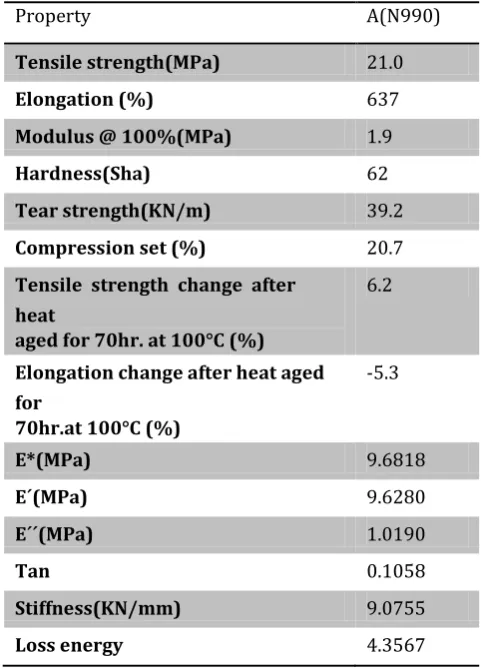
Table No- 2 Properties of hard rubber
Property A(N990)
Tensile strength(MPa) 21.0
Elongation (%) 637
Modulus @ 100%(MPa) 1.9
Hardness(Sha) 62
Tear strength(KN/m) 39.2
Compression set (%) 20.7
Tensile strength change after heat
aged for 70hr. at 100°C (%)
6.2
Elongation change after heat aged for
70hr.at 100°C (%)
-5.3
E*(MPa) 9.6818
E´(MPa) 9.6280
E´´(MPa) 1.0190
Tan 0.1058
Stiffness(KN/mm) 9.0755
© 2019, IRJET | Impact Factor value: 7.211 | ISO 9001:2008 Certified Journal | Page 850 Table No - 3 Properties of spring
3. SIMULATION
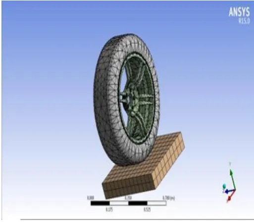
Generally, as we are draw the chassis diagram for using pro-e softwarpro-e andimporting the mesh diagram for using ansys software. The meshed model name automatic and the simulation contain for number of nodes is 48467 and number of element is 24825 and were generated in ansys preprocessing system.
[image:3.595.31.291.127.449.2]
Fig -1: Modeling diagram for spare wheel
Fig 1 shows Model geometry from the pro-e have been imported in the form of iges. And the material properties of the element have been specified. Also the detail of the bounding material & contact detail have seen specified. Fig 2 represents mesh model of spare wheel.
Fig – 2: Mesh model of spare wheel.
Table No -4 Meshing Configuration.
Material Chrome ASTM A 401
Nominal Analysis C -51 -59% Cr -60 - 80%
Si1 -20 -1.60%
Minimum Tensile Strength
235-300
Modulus of Elasticity E psi x 103
30
Design Stress % Minimum Tensile
45
Modulus in Torsion G psi x 106
11.5
Maximum Temp. °F 475 Maximum Temp. °C 246 Rockwell Hardness C48-55 Method of Manufacture
Chief Uses
Cold drawn and heat treated before
Special Properties Fabrication. Used for shock loads and
Moderately elevated temperature.
Object Name Mesh
State Solved
Defaults
Physics Preference Mechanical Solver Preference Mechanical APDL
Relevance 0
Sizing
Use Advanced Size Function
[image:3.595.307.564.180.404.2] [image:3.595.35.252.575.727.2]© 2019, IRJET | Impact Factor value: 7.211 | ISO 9001:2008 Certified Journal | Page 851
Relevance Center Coarse
Element Size Default
Initial Size Seed Active Assembly
Smoothing Medium
Transition Fast
Span Angle Center Coarse
Minimum Edge Length 8.6588e-005 m
Inflation
Use Automatic Inflation None
Inflation Option Smooth Transition
Transition Ratio 0.272
Maximum Layers 5
Growth Rate 1.2
Inflation Algorithm Pre
View Advanced Options No
Triangle Surface Mesher Program Controlled
Topology Checking Yes
Advanced
Number of CPUs for Parallel Part
Program Controlled
Meshing
Shape Checking Standard Mechanical
Element Midside Nodes Program Controlled
Straight Sided Elements No
Number of Retries Default (4)
Extra Retries For Assembly
Yes
Dimensionally Rigid Body Behavior
Reduced
Mesh Morphing Disabled
Disfeaturing
Pinch Tolerance Please Define
Generate Pinch on Refresh
No
Automatic Mesh Based Disfeaturing
On
Here the meshed component, where the loading & constrain have been applied. Where the bases of the road have been constrained for zero degree removal, hence the
bases have been fixed. Loading of tyre have been done, throughout the surface of the tyre.
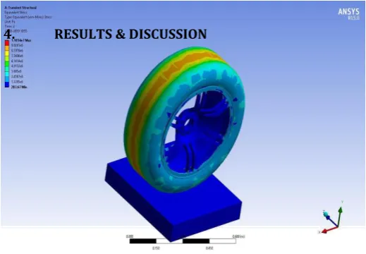
[image:4.595.29.249.115.748.2]4. RESULTS & DISCUSSION
[image:4.595.306.566.297.477.2]Fig – 3: Total deformation Analysis of spare wheel (17500N).
Fig – 4: Equivalent stress Analysis of spare wheel (17500N).
Fig 3 & 4 indicates the total deformation and equivalent stress of spare wheel when maximum load applied (17500N). Maximum 2.3986e-005 m deformation & 1.1054e+007 Pa equivalent stresses are obtained. When
Defeaturing Tolerance Default
Statistics
Nodes 48467
Elements 24825
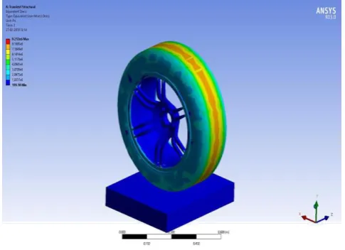
[image:4.595.309.562.532.685.2]© 2019, IRJET | Impact Factor value: 7.211 | ISO 9001:2008 Certified Journal | Page 852 applied minimum load 12500 N the minimum 2.0054e-005
[image:5.595.306.521.122.262.2]m deformation and 9.212e+006 Pa equivalent stress obtained.
Fig – 5: Total deformation Analysis of spare wheel (12500N).
Fig – 6: Equivalent stress Analysis of spare wheel (12500N).
Chart – 1: Variation of Deformation in spare wheel.
Chart -2: Variation of Stresses in spare wheel.
5. CONCLUSION
This is carried out by us made an impressing task in four wheelers. It is very useful for parking four wheelers, because they need not take any risk for park the vehicle and quick operation. This project will reduce the cost involved in the concern. The spare wheel has been designed to analysis using CFD software. Aim for development of a system to useful in the automotive sector. It will be implementing for working of fifth wheel, our aim is to fold the fifth wheel axel for better space adaptability. Hence whenever needed operated must have unfold the fifth wheel axel by actuating rack and pinion. Arrange conventional steering system at front side.
REFERENCES
[1] Mr.Paresh,et, al., auxillary drive wheel vehicle parking mechanism(fifth wheel car parking mechanism), ISSN:1314-3395 volume 118, Issue-24, MAY-28 2018.
[2] Tiberiu riurgiu, et,al., Static and Transient Analysis of Radial Tires Using ANSYS, ISBN:978-1-61804-186-9
[3] Amol banker,et,al., tyre cornering analysis using finite element analysis and comparison with experiment, ISBN:978-93-82702-84-9, 29th MAR-2015.
[4] Sadda. Mahendra,et,al., Effect of Tyre Overload and Inflation Pressure on Rolling Loss (resistance) and Fuel Consumption of Automobile Cars, ISSN (e): 2250 – 3005, Vol- 04, Issue, 10, October– 2014
[5] D.Madhusudhana,et,al., effect of tyre overload and inflation Pressure on rolling loss & fuel consumption Of automobiles cars, ISSN: 2349-2163, Volume-1, Issue-8, Sep-2014
[6] xiaoguang yang, finite element analysis and experimental Investigation of tyre characteristics for developing Strain-based intelligent tyre system, sep-2011.
[image:5.595.40.283.141.317.2]© 2019, IRJET | Impact Factor value: 7.211 | ISO 9001:2008 Certified Journal | Page 853 [8] R. Van der steen,et,al., tyre/road friction modeling,