Smart Guide Stick for Blind
Kushnav Das
UG Student, Department of Electronics and Communication Engineering, Institute of Engineering and Management,
Salt Lake, Sector-V, Kolkata, West Bengal, India.
---***---
Abstract - Obstacle detection is one of the major concernsfor a fully or a partially blind person. This paper describes guide blind walking stick based on ultrasonic sensor with the use of arduino nano. According to World Health Organization (WHO), 30 million peoples are permanently blind and 285 billion peoples with vision impairment. In this paper discuss about smart guide blind stick which is proficient of detecting any obstruction, detect corners and even allow the user to find the stick if anyhow missed by the user by pressing a remote switch. The device is designed with an objective to sort out common issues faced by the blind people while using conventional sticks. With the electronics embed within the stick, it became a smart stick. Presented here is a smart guide blind stick using Arduino nano. The stick uses Ultrasonic sensors for obstacle detection. The main aim of this paper is to detect nearby obstacle and notify the user of the direction of that obstacle, thereby enabling the user to determine the corrective direction to head.
Keywords – Smart Stick, Ultrasonic Sensor, Arduino nano, Microcontroller.
Introduction
According to WHO, it is estimated that approximately 30 million peoples are permanently blind and 285 billion peoples with vision impairment[1].Visually impaired people are the people who find it difficult to make out the smallest detail with healthy eyes. Those who have the visual acuteness of 6/60 or the horizontal range of the visual field with both eyes open have less than or equal to 20 degrees. These people are regarded as blind. A survey by WHO (World Health Organization) carried out in 2011 estimates that in the world, about 1% of the human population is visually impaired (about 70 million people) and amongst them, about 10% are fully blind (about 7 million people) and 90% (about 63 million people) with low vision. Smart guide blind stick is an innovative stick designed for visually disabled people for enhanced direction-finding. In this paper a highly developed blind stick that allows visually challenged people to navigate with ease using advanced technology. The smart guided blind stick is incorporated with ultrasonic sensor along with light sensing. In this paper ultrasonic sensors use to
detect obstacle in front using ultrasonic waves. On sensing obstacles the sensor triggers the microcontroller. There after microcontroller processes this signal and calculates distance of the obstacle. If the obstacle is not close enough then circuit does nothing. If the obstacle is close to the blind person then microcontroller sends a signal to buzzer. One more quality is that it allows the blind person to detect the light intensity (light or darkness) of the place. The device has another sophisticated feature integrated to help the blind find their stick if they forget where they kept it. A wireless rf based module is used for this purpose. Pressing the remote button sounds a buzzer on the stick which helps the blind person to find their stick. Thus this system allows for obstacle detection as well as finding stick if misplaced by visually disabled people [2-3].
Block diagram of the Scheme
Software requirements
Arduino is open source, which means hardware is reasonably priced and development software is free.
Hardware requirements Arduino nano
Arduino nano is a surface mount version with integrated USB. It is a smallest, complete, and breadboard friendly. It has everything that has (electrically) with more analog input pins and onboard +5V AREF jumper. The Arduino nano is automatically sense and switch to the higher potential source of power, there is no need for the power select jumper. This new version comes with ATMEGA328P which offer more programming and data memory space.
Specifications:
Microcontroller: Atmel
ATmega328
Operating Voltage (logic level): 5 V
Input Voltage (recommended): 7-12 V
Input Voltage (limits): 6-20 V
Digital I/O Pins: 14 (of which 6
provide PWM output)
Current per I/O Pin: 40 mA
Flash Memory: 32 KB (of which
2KB used by bootloader)
SRAM: 2 KB
EEPROM: 1 KB
Clock Speed: 16 MHz
Dimensions: 0.70” X1.70”
Ultrasonic transducers
The HC-SR04 ultrasonic sensor module uses sonar to resolve distance to an object like bats or dolphins do. It offers exceptional non-contact range detection with high precision and stable readings in an easy-to-use package ranging from 2 cm to 400 cm. It operation is not precious by sunlight or black material like Sharp rangefinders. It comes entire with ultrasonic transmitter and receiver module. The basic principle of the module as follows:
(1) Using I/O trigger for at least 10 us high level signal,
(2) The Module repeatedly sends eight 40 kHz and detect whether there is a pulse signal back.
(3) IF the signal back, through high level , time of high output I/O duration is the time from sending ultrasonic to returning. Test distance = (high level time×velocity of sound (340M/S) / 2)
RF module
RF Module Specifications
1. Wireless (RF) Simplex: Transmitter and Receiver
2. Transmitter Operating Voltage: +5V DC
3. Transmitter Operating current: 9mA- 40mA
4. Operating frequency: 433 MHz
5. Modulating Technique: ASK (Amplitude shift keying)
6. Data Transmission speed: 10Kbps
Bzzer
The piezo buzzer produces sound based on reverse of the piezoelectric effect. The generation of pressure variation or strain by the application of electric potential across a piezoelectric material is the underlying principle. These buzzers can be used alert a user of an event corresponding to a switching action, counter signal or sensor input. They are also used in alarm circuits. The buzzer produces a same noisy sound irrespective of the voltage variation applied to it. It consists of piezo crystals between two conductors. When a potential is applied across these crystals, they push on one conductor and pull on the other. This, push and pull action, results in a sound wave. Most buzzers produce sound in the range of 2 to 4 kHz.
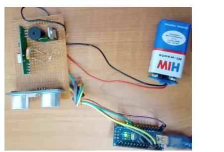
Circuit & Working
Circuit shown below operates using a minimum of 5V DC power supply. The Arduino itself requires only 5V to operate but considering the fact that it has to power
ultrasonic module, one piezo-electric buzzer as well as vibrating motor. Arduino has an inbuilt 5V voltage regulator. The heart of the circuit is Arduino nano MCU board. The Ultrasonic sensor “HC-SR04” is used for obstruction detection using ultrasonic signal. These sensors require a power supply of 3.3V to operate up to a distance of 400 cm and can detect obstacles within an average angle of 25 degrees in the sphere. Apart from this, a peizo-electric buzzer and a vibrating motor are connected so that it can guide the blind persons using different tones and vibration depending upon distance of obstacle from stick .The Arduino is programmed in such a way that on switching ‘ON’ the Arduino, it sends a LOW to HIGH signal on the TRIG pin of all the Ultrasonic sensors. The ultrasonic sensor will send an Ultrasonic wave using the ultrasonic transmitter of the module. These ultrasonic waves travel through air and on colliding with an obstacle, get reflected back. Programming is done in such a way, that when this obstacle is in the range of 1.2 m of the sensor, the Arduino will send the signal to the buzzer. To further improve its performance, if the obstacle is too close (less than 0.6 m from sensor) then the vibrating motor is also activated. The sensor would give an electrical response at the ECHO pin of the sensor. This response is the time taken by the wave for a round journey from sensors to obstacle and back to the sensors. For our calculation, we need only the one-way distance. This can be calculated by Arduino using the following formula:
Distance = {(Duration/2) / (2/29.1)}
Here, Duration = Echo output; and since we need only one-way distance, hence we divide this duration by 2. Here the constant 29.1 is derived as follows:
The speed of sound is 343.5 m/s or 0.0345 cm/microseconds.
1/0.0345 cm/microseconds is 29.1 microseconds/cm.
Dividing the Duration (ms) by 29.1(microseconds/cm) gives us the distance in (cm).
An additional provision of a motor that vibrates the stick is planted into the assembly for very near obstacles. Experimentation study shows the optimum distance post
assembly, to be 0.6 m. There are two circuits in the device -
remote switch and the smart blind stick. The remote switch is simply an RF transmitter circuit with a switch connected to the D3 pin of the encoder IC. The remote switch has the following circuit connections -
RF Transmitter - The RF transmitter is used to transmit the missing alert to the receiver circuit on the smart stick. The RF transmitter module is a small vero board sub-assembly. The smart stick is built on Arduino nano and has RF receiver circuit, ultrasonic sensor, LDR sensor and Buzzer connected to the Arduino board. The circuit connections of the smart stick are as follow -
RF Receiver - The RF receiver detects the missing alert of the RF data. The receiver detects the radio signal carrying the alert information.
LDR Sensor - The LDR sensor is used to identify the intensity of the light (dark and lighted ) of places. The LDR sensor is connected to the A1 pin of Arduino board. The sensor is connected in a voltage divider circuit. The LDR provides an analog voltage which is converted to digital reading by the inbuilt ADC of the microcontroller.
Power Supply - Both the circuits need a 5V regulated DC for their operation. Two 9V battery can be used as the primary source of power in each circuit. The supply from the battery can be regulated to 5V using 7805 voltage regulator IC. The pin 1 of the voltage regulator IC should be connected to the +ve terminal of the battery and pin 2 of it should be connected to the ground. The voltage output must be drawn from pin 3 of the 7805 IC.
Buzzer - The buzzer is directly interfaced at the pin 12 (D12) pin of the Arduino. The buzzer is activated as any obstacle is detected by the ultrasonic sensor, dark places are detected by LDR sensor or the missing alert is passed by the RF circuit.
Stick location finding - If any how the user loses the stick, he can press the remote switch which set the D3 bit of the RF encoder to HIGH. The same logic is relayed at the D3 bit of the RF decoder and passed to the Arduino. On receiving a HIGH logic at the pin, the Arduino send a pulse at the buzzer which lasts for a variable duration depending upon the distance of the remote from the stick.
[image:4.612.351.577.90.243.2]Light detection - The light detection is done by the LDR sensor and is used to detect the dark places. The sensor connected to a voltage divider circuit output an analog voltage at the interfaced controller pin. The analog voltage is read and digitized using inbuilt ADC channel [4-5].
Fig. Circuit diagram of device.
Future scope
A lot of future scope are available that can be used with the stick such as usage of Global positioning System and GSM can be incorporate with this stick that can helpful to blind person to easily locate the destination route information and to communicate the location to a relative or care giver. GPS and GSM can help to find the shortest and best path as accordingly to Google map. GSM addition can help in future for any immediate sufferer help. It can also contain special arrangement to connect the walking stick to aadhar card link of blinds, helping the government serve the physically disable even better.
Conclusions
in all developing countries were on top of our priorities. The device constructed in this work is only capable of detecting obstacles and moisture. Holes cannot be detected using neither this device nor the nature of obstacle. Therefore, a better device can be constructed using ultrasonic sensors, arduino nano and other devices that employ audio commands to alert the user of what is in his path of movement. A vibrator may also be added for ease of use and convenience.
References
[1] R.Dhanuja, F.Farhana, G.Savitha, India, ISSN: 2395-0056/ 2018 IRJET. “Smart Blind Stick using Arduino”.
[2] G. Gayathri, M. Vishnupriya, R. Nandhini and M. Banupriya “Smart Walking Stick for Visually Impaired.” International Journal of Engineering and Computer Science, vol. 3, number 3, pp. 4057-4061, 2014.
[3] R. Radhika, P.G. Pai, S. Rakshitha and R. Srinath “Implementation of Smart Stick for Obstacle Detection and Navigation.” International Journal of Latest Research in Engineering and Technology, vol. 2, number 5, pp. 45-50, 2016.
[4] E. J. Chukwunazo and G. M. Onengiye “Design and Implementation of Microcontroller Based Mobility Aid for Visually Impaired People.” International Journal of Science and Research. Vol. 5, issue 6, pp.
680-686, 2015. Available at
http://dx.doi.org/10.21275/v5i6.NOV164233.