Space Flight Operations Contract
Contract NAS9-20000 DRD - 1.4.3.8-a
HAL/S COMPILER SYSTEM
SPECIFICATION
PASS 32.0/BFS 17.0
HAL/S COMPILER SYSTEM SPECIFICATION
DRD - 1.4.3.8-a Approved by
Original Approval Obtained Barbara Whitfield, Manager
HAL/S Compiler and Application Tools
Original Approval Obtained Monica Leone, Director
The HAL/S-FC Compiler System Specification has been revised and issued on the following dates1:
1. A table containing the Revision History of this document prior to the USA contract can be found in Appendix B.
Issue Revision Date Change Authority Sections Changed
29.0/14.0 03/10/1999 CR12935A 3.1.1.3 App. B
-p. 3-5, 3-6 -p. B-5, B-8 CR12940 2.6.1
2.6.2 2.6.6 3.3
-p. 2-6
-p. 2-6, p.2-7, -p. 2-9
-p. 3-60, 3-61 CR13043 5.2.3
5.2.7 5.3.3 5.3.4
-p. 5-2 -p. 5-11
-p. 5-168, 5-175 -p. 5-240
DR109091 2.6.2 -p. 2-7 DR109089 3.1.1.3 -p. 3-5
Cleanup -p. 2-4 -p. 3-4
- pp. 5-9, 5-10, 5-12, 5-34, 5-35, 5-37, 5-42 thru 5-45, 5-47, 5-50, 55, 61, 63, 64, 67, 5-68, 5-70, 5-72, 5-74, 5-75, 5-80, 82, 85, 93, 94, 96, 99, 101, 103, 106, 111, 113, 114, 116, 118 thru 5-125, 5-128 thru 5-131, 5-134 thru 5-136, 5-139 thru 5-143, 5-145, 147 thru 149, 151 thru 163, 166, 167, 169 thru 188, 190, 192, 194 thru 5-221, 5-226, 5-227, 5-230, 5-234 thru 5-236, 5-240, 5-242, 5-246, 247, 250, 257, 264, 5-267, 5-271, 5-272, 5-274, 5-278, 285, 287, 289, 293, 5-295, 5-296, 5-299, 5-300, 5-307, 315, 317, 319, 322, 5-323, 5-325 thru 5-342 -p. 6-4 -p. 7-5
30.0/15.0 06/12/00 CR12214 4.2 App. A
-p. 4-2 -p. A-3 CR12620 App. B -p. B-4 CR13211 App. A -p. A-3 CR13217 1.3
3.1.15.3 7.5 App. B
-p. 1-2
-p. 3-60, 3-61 -p. 7-6
-pp. B-5, B-8 CR13222 5.2.4.3 5.3.1 5.3.2 5.3.3 5.3.4 5.3.6 5.3.7
-pp. 5-3 thru 5-8 -pp. 5-39
-pp. 5-59, 5-79, 5-82, 5-83, 5-116, 5-118
-pp. 5-133 thru 135, 5-141 thru 144, 146, 5-149, 5-161, 5-213 -pp. 5-241
-pp. 5-294
-pp. 5-330, 5-331 DR111314 7.2.3 -p 7-2
Cleanup Preface
31.0/16.0 09/07/01 CR13454 2.6.3 3.1.1.1 3.1.1.3 3.1.1.5 3.1.10.4 3.1.12.5 3.1.14.1 3.1.14.2 3.1.15.2 3.1.17 6.3 6.3 -p 2-7 -p 3-2 -p 3-5 -p 3-9 -p 3-47 -p 3-56 -p 3-62 -p 3-63 -p 3-64 -p 3-70 -p 6-28 -p 6-34
CR13462 sec 4.0 -p 4-1 to 4-10 CR13372 3.1.1.2 -p 3-3, 3-4 DR111359 3.1.15.4 -p 3-69 DR111364 3.1.5.3
3.1.7.4
-p 3-31 -p 3-39
Cleanup Preface
32.0/17.0 11/2005 CR13538 3.1.1.3 3.1.14.1 3.1.14.2 3.1.15.2 3.1.15.4
-pp. 3-5 thru 3-7 -pp. 3-62, 3-63 -pp. 3-63, 3-64 -p 3-66
CR13570 3.1.15.5 3.3.4 3.3.6 8.3.2 8.4
-pp. 3-71, 3-72 -p 3-75
-p 3-75 -p 8-3 -p 8-4 CR13652 3.1.1.3
3.1.14.1 3.1.14.2 3.1.15.3 3.1.17 4.2.3.3 8.3.1 8.4
-pp. 3-6, 3-7 -p 3-62
-p. 3-64, 3-65 -p 3-69
-p 3-72 -p. 4-6 -p 8-3 -p 8-4 CR13811 3.1.1.3 -p 3-5 CR13833A 2.10 -p 2-11 CR14216A
1.3 4.2.1.2 7.1.2
The current status of all pages in this document is as shown below:
Page No. Change No.
All 32.0/17.0
The HAL/S FC Compiler System Specification was developed by Intermetrics, Inc. and is currently maintained by the HAL/S project of United Space Alliance. The manual identifies the informational interfaces with the HAL/S-FC compiler and between the compiler and the external environment.
Over the years, numerous changes have been made to the HAL/S-FC compiler design and this document has been modified to reflect these changes. However only a small number of these changes have been incorporated into the HAL/S-360 compiler and now this document is only an approximation of that compiler’s design. Earlier versions of the predecessor of this document (IR-182) contain a more accurate representation of the design of the HAL/S-360 compiler’s components. The earliest of these versions should be referenced when attempting to understand the design of the HAL/S-360 compiler, and this document should be referenced when attempting to understand the design of the HAL/S-FC compiler.
The primary responsibility is with USA, Department, 01635A7.
Questions concerning the technical content of this document should be directed to Danny Strauss (281-282-2647), MC USH-635L.
Table of Contents
i November 2005
Table of Contents
ii November 2005
Table of Contents
iii November 2005
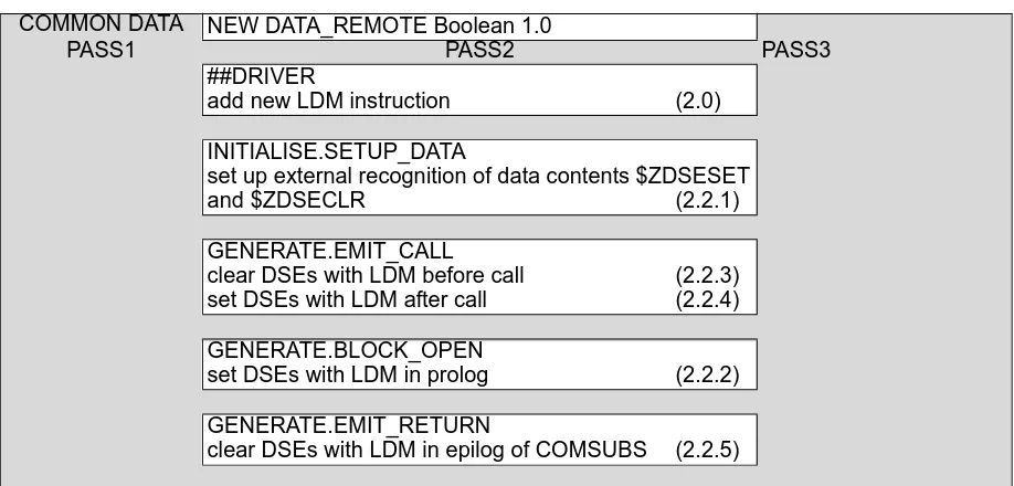
3.1.11.3 Shaping Functions ... 3-53 3.1.12 Real Time Statements ... 3-54 3.1.12.1 WAIT Statement ... 3-54 3.1.12.2 CANCEL, TERMINATE Statements ... 3-54 3.1.12.3 SIGNAL, SET, RESET Statements ... 3-55 3.1.12.4 UPDATE PRIORITY Statement ... 3-55 3.1.12.5 SCHEDULE Statement ... 3-55 3.1.13 I/O Statements ... 3-56 3.1.13.1 Initiation ... 3-56 3.1.13.2 Input ... 3-56 3.1.13.3 Output ... 3-59 3.1.14 NAME Operations ... 3-62 3.1.14.1 NAME Comparisons ... 3-62 3.1.14.2 NAME Assignment ... 3-63 3.1.15 %MACROS ... 3-66 3.1.15.1 %SVC ... 3-66 3.1.15.2 %NAMECOPY ... 3-66 3.1.15.3 %COPY ... 3-66 3.1.15.4 %NAMEADD ... 3-70 3.1.15.5 %NAMEBIAS ... 3-71 3.1.16 NONHAL References ... 3-72 3.1.17 Block Move Algorithm ... 3-72 3.2 Object Code Naming Conventions ... 3-74 3.3 Printed Data from Phase 2 ... 3-74 3.3.1 Formatted Assembly Listing ... 3-74 3.3.2 Symbol Information ... 3-75 3.3.3 RLD Information ... 3-75 3.3.4 Variable Offset Table ... 3-75 3.3.5 Memory Map Table ... 3-75 3.3.6 Structure Template Layout Table ... 3-75 3.4 Symbol Table Augmentation ... 3-75 3.5 Statement Table Augmentation ... 3-76 4.0 Incremental #D (DATA_REMOTE Directive) REQUIREMENTS AND CODE DESIGN
4-1
Table of Contents
iv November 2005
Table of Contents
v November 2005
List of Tables
vii November 2005
List of Tables
viii November 2005
List of Figures
ix November 2005
1.0 Introduction
1.1 Scope of Document
This document specifies the informational interfaces within the HAL/S-FC compiler, and between the compiler and the external environment. An overall description of the compiler, and the hardware and software compatibility requirements between compiler and environment are detailed in the HAL/S-FC Compiler System Functional
Specification.2 Familiarization with the Functional Specification is presumed throughout this document.
This Compiler System Specification is for the HAL/S-FC compiler and its associated run time facilities which implement the full HAL/S language.3 The HAL/S-FC compiler is designed to operate "stand-alone" on any compatible IBM 360/370 computer and within the Software Development Facility (SDF) at NASA/JSC, Houston, Texas.
1.2 Outline of the Document
The HAL/S-FC compiler system consists of:
The organization of this document is based upon the organization of the compiler system. Each part of the system is considered as a separate entity with its own specific function and interfaces to other parts. Hence, there are four sections which cover the parts of the system as follows:
In addition to this part-by-part documentation, the compiler system, taken as a whole, exhibits properties and interfaces which are not specific to any one of the pieces. General information about such topics as the compiler's operating environment and user-written interfaces to emitted object code are contained in Section 6. Several Appendices are included which deal with tabular data used in the compiler system.
2. HAL/S-FC Compiler System Functional Specification, 24 July 1974, IR-59 3. HAL/S Language Specification, USA003088
1. a seven phase language processor (compiler) which produces object modules compatible with AP-101 Space Shuttle Support Software and a set of simulation tables to aid in run time verification.
2. a comprehensive run-time library which provides an extensive set of mathematical, conversion, and language support routines.
Section 2 - describes Phase 1 and the syntax analysis phase of the compiler. Section 3 - describes Phase 2 and the code generation phase and specifies in
detail the code patterns for specific HAL/S constructs.
Section 4 - describes Phase 3 and the operation of the Simulation Data File generator.
1.3 Status of Document
This document, plus the HAL/S-FC Compiler System Functional Specificationfor the AP-101 comprise the complete HAL/S-FC Compiler System Specification.
The HAL/S-FC compiler inherits some of its operational features from the HAL/S-360 compiler system for which a similar Specification exists. In addition, many features of the HAL/S-FC system are under control of Interface Control Documents which are subject to update. When appropriate within this document, references are made to these companion documents as sources of supplementary material and in some cases as primary sources of detailed information.
The following list of documents represents the set of additional documents which reflect design and control of the HAL/S-FC compiler system:
• HAL/S-FC Compiler System Functional Specification for the AP-101, IR–59. • Interface Control Document: HAL/FCOS, (a.k.a. HAL/FCOS ICD), USA001460. • Interface Control Document: HAL/S-FC/SDL, (a.k.a. HAL/SDL ICD), USA001556. • HAL/S-360 Compiler System Specification, USA001528.
• HAL/S Language Specification, USA003088.
2.0 Phase 1 - Syntax Analysis
The Syntax Analysis Phase performs syntactic and semantic analysis of the user's HAL/S source programs. It performs all functions necessary to allow an independent Phase 2 program to generate code for the target computer. The basic design of the HAL/S system includes use of a single Phase 1 for a variety of target machine Phase 2s. Thus, the Phase 1 used by the HAL/S-FC compiler is the same one used in the HAL/S-360 compiler. In this section on Phase 1, data which is supplied in detail in the
HAL/S-360 Compiler System Specification is not repeated. Instead, reference is made to the proper section of that document.
This section deals with the following Phase 1 functions: • Primary Source Input
• Secondary Source Input
• ACCESS System Implementation • Compiler Directives
• Template Checking and Generation • Printed Data
• Symbol Table Creation • Statement Table Generation • Literal Table Generation • HALMAT Creation • The Optimizer
2.1 Primary Source Input
Phase 1 accepts primary source input in the form of fixed length logical records. This input must be defined by the SYSIN DD statement in the JCL invoking the compiler. The first byte of each record is used to define the type of the record as follows:
(Other letters can be used if modified via the "CARDTYPE" compiler option to a legal type.)
For stand-alone operation the source records are 80 bytes in length and may contain data in columns 2-80. Optionally, the user may designate, via the "SRN" compiler option, that the source scanning is to stop at position 72 and also that positions 73-78 are to be printed on the listing as "Statement Reference Numbers".
When operating in the SDL environment, indicated by use of the "SDL" compiler option, the source records must still be all the same length but that length may be from 80 to
132 characters. When in the SDL mode, the compiler accepts source data from record positions 2 through 72. In addition, when the records are of sufficient length, the following fields are recognized and all except the change authorization field are printed on the primary source listing:
• Record Sequence Number - positions 73 through 78; • Record Revision Indicator - positions 79 and 80; • Change Authorization Field - positions 81-88
• Portions of records beyond position 88 are ignored.
The compiler's primary input may optionally be in a compressed source format as defined in the HAL/SDL ICD. No special notification of use of compressed source is needed. Phase 1 determines the type of input by examining the first record. Catenated datasets defined as primary compiler input must all be either in compressed or
noncompressed format for one invocation of the compiler.
2.2 Secondary Source Input - The Include System
The user may direct the compiler to an alternate input source by use of an INCLUDE compiler directive in the primary input. The exact form of the INCLUDE directive may be found in Section 5.2 of the HAL/S-FC User's Manual.
The INCLUDE directive defines a member name in a partitioned dataset. Phase 1 uses a FIND macro to locate the member on the INCLUDE DD card. If the FIND is
unsuccessful, an identical FIND is issued for the OUTPUT6 DD card. A member, when located, is read to its end by the compiler. The records are processed identically to primary (SYSIN) input with the exception that further INCLUDE directives within INCLUDE'd source are not allowed. The same source margins are applied to the INCLUDE'd source as are applied to the primary input. In addition, the compiler prints a line in the primary source listing indicating the catenation sequence number of the DD card on which the member was found and the RVL field from the PDS directory entry for the member. The RVL field is the first 2 bytes of user data after any TTRNs. The individual members which are INCLUDE'd may be in either compressed or uncompressed format, independent of whether the primary input was compressed. The form of each INCLUDE'd member is determined by the compiler from the first record read.
Partitioned datasets may be catenated together in the JCL to form the INCLUDE DD sequence, but such datasets must have identical DCB attributes.
2.3 Access Rights Implementation
Any variable in a COMPOOL template or any external routine to which the ACCESS attribute has been applied is considered to be restricted for the compilation unit which is being compiled. The restriction is slightly different for variables than for blocks:
These restrictions may be selectively overridden for individual variable and block names. The selection of which ACCESS controlled names are to be made available to the unit being compiled is performed by processing an external dataset. The external dataset is known as the Program Access File (PAF). The PAF must have partitioned organization and is specified by the following JCL:
//HAL.ACCESS DD DSN=<PAF name>, <other parameters>
where the <PAF name> is the dataset name of the PAF without any member specification.
Each member of the PAF contains the information about ACCESS controlled names which are to be made available to one unit of compilation. The member name is defined by a Program Identification Name (PIN). The PIN is specified to the HAL/S-FC compiler by using the PROGRAM compiler directive in the primary input stream:
col 1
D PROGRAM ID = <id>
The <id> field of the directive is a 1 to 8 character identifying name which is used to select the member of the PAF to be processed for the current compilation's ACCESS information. The appearance of the PROGRAM directive in the compiler's input stream causes immediate processing of the PAF member specified.
The format of an individual PAF member is described below.
a. Variables with the ACCESS attribute may not have their values changed.
b. Block names may not be used at all.
a. Column 1 of each record is ignored except when column 1 contains the character "C", in which case the entire record is ignored.
b. The portion of each record which is processed is the same portion which is processed in the primary compiler input (SYSIN).
c. COMPOOL elements which are to be made available to the compilation are specified as:
<COMPOOL-name>($ALL)
<COMPOOL-name>(<var-name>, <var-name>,…<var-name> or The first format specifies access to individual variables within the named COMPOOL. The second format specifies access to all variables within the named COMPOOL.
d. Access to external block names is specified as:
$BLOCK(<ext-name>, <ext-name>,…<ext-name>)
Some validity checking is performed by the compiler while processing the PAF member. Warnings are issued for the following conditions:
If, at the time the PROGRAM directive is encountered, there have been no ACCESS-controlled variables declared, the PAF is not opened. If a user does not require access to any, the PROGRAM directive and associated PAF members may be omitted.
2.4 Compiler Directive Parsing
When an input record is found which contains a "D" in column one, Phase 1 scans the remainder of the card for a valid compiler directive. A list of legal compiler directives and their function is listed in Section 5.2 of the HAL/S-FC User's Manual.
Directive processing is done independently of HAL/S source language parsing, i.e. words used on Directive cards are not necessary HAL/S language keywords. Similarly, HAL/S language keywords are not recognized as such on Directive cards.
2.5 Template Checking and Generation
Phase 1 assumes the task of source template verification and generation. Every compilation unit in the HAL/S-FC system has a source template. When the block header for a unit of compiler is encountered, Phase 1 begins to construct the source template for that unit as follows.
The member name for the template being created is determined. This is done by taking the "characteristic name" for the unit and preceding it by the characters '@@'. The characteristic name for any unit is created by taking the block name, removing any underscore characters, and then padding or truncating the result to 6 characters. An attempt is made to locate a member of this name on either the INCLUDE or OUTPUT6 DD cards. If such a member is found, the contents of the member are compared with an internal, temporary template created as the compilation proceeds. If the existing template and the internal one agree, a template update is not required, and the existing template remains intact. If the templates do not agree, the internal template is written to the OUTPUT6 DD card and STOW'ed with the current member name. If the initial search for an existing template fails, the generated template is automatically written and STOW'ed on the OUTPUT6 DD card. The PDS directory entry for a template member is created with two bytes of user data. The two bytes are initialized to X'F0F0'.
f. Either of the constructions (c) or (d), above, may span more than one record. g. The name of the particular COMPOOL in the form (c) above may appear more
than once; i.e. the variables in a particular COMPOOL do not have to be specified at one time. Similarly, the form $BLOCK may appear more than once.
1. A syntax error on a PAF record- the bad record is printed. 2. Names mentioned in the PAF are not defined.
3. Elements of $BLOCK in the PAF are not defined.
4. Requests for names which are not ACCESS protected. 5. Variables found, but not within the COMPOOL specified.
Phase 1 also sets appropriate bits in a field which is passed back to the caller of the compiler as the high order byte of register 15. The definitions of these bit settings is defined in the HAL/SDL ICD.
Generation of the internal template is performed during syntax analysis on a token by token basis. As statements are encountered which are required in the template, the tokens from the statements are added to an internal buffer. When a new token will no longer fit in the buffer, the buffer is written and cleared for continuation. Thus, the templates take the form of strings of HAL/S tokens separated by one block. The template statements are continued from one line to the next without regard for
statement boundaries, thus producing the template in the most compact form possible. For the comparison of existing templates with new, generated templates, the generated records are compared character for character with the existing records. Any mismatch is considered to indicate a change in the template.
Templates are never generated using the compressed source format mentioned in Section 2.1. The generated templates conform to the source margins in effect for the compilation (e.g. for an SDL mode compilation, templates are created with source in position 2 through 72 of the records. When template records are written to the
OUTPUT6 DD card, the records are padded with blanks or truncated as necessary to conform to the LRECL specification for that DD card.
When a template has been found to have changed, the compiler updates a "Version number" associated with the template. For an existing template, the version number is found on a VERSION compiler directive card at the end of the existing template
member. If a new template is needed, the version number is incremented by one and placed on a new VERSION directive card at the end of the generated template. The version number is limited to the range 1 to 255. Upon reaching 255, the next
incrementation causes the number to begin again at 1. When no existing template can be located, the version is set to 1.
When templates produced by the compiler are referenced in subsequent compilations by use of an INCLUDE for the template, the version numbers from the referenced templates are emitted into the produced object code on special SYM records which indicate the versions of all external references. In addition, the emitted object code for any compilation unit contains a SYM record indicating the version number of the
template created for that compilation unit. This information permits the checking, if desired, of proper integration of separately compiled units by providing information necessary for cross-checking of inter-module references.
2.6 Listing Generation 2.6.1 Options
2.6.2 Primary Formatted Listing
The central printed output of the compiler is the primary source listing. This listing is designed to document the actions taken by the compiler during its generation of an executable form of the user's source program in an indented, annotated format.
Additional information, such as block summaries and symbol table listings, are also part of the primary source listing.
The formatting of the primary source listing leads to the documentation of the users program in two ways: 1) variable annotation, and 2) logical indenting.
When operating in the SDL, additional information is provided on the primary source listing. The Record Sequence Number and Record Revision Indicator fields (see Section 2.1) are printed on the primary source listing next to the statements to which they apply. The revision level is printed to the right of the statement immediately following the vertical bar. Another vertical bar separates the revision level from the current scope. Additional details of the specific operations performed during SDL operation may be found in the HAL/SDL ICD.
All lines are single-spaced except for the following: there is a blank line before a group of one or more E-lines, C-lines or D-lines and after a group of one or more S-lines. For D INCLUDES, the first statement number associated with the include is printed. If there is an IF-THEN or IF-THEN-ELSE statement followed by a simple DO, the DO appears on the same line as the IF-THEN or ELSE except when the combination of the statements is too long for a single line. The combined IF-THEN and DO statements (including the semicolon of the DO) will be broken into multiple lines following regular compiler rules. The statement number for the IF-THEN will be printed as the statement number for each line. If the THEN and the DO or the ELSE and the DO are separated by a C-line or a D-line, the DO will be placed on its own line with its own statement number.
Normally, the current scope is printed to the right of each line in the compilation listing. The value in the scope field will be truncated if it exceeds the maximum line length. The following list indicates instances where the current scope will be replaced by a different value:
a. The scope field for END statements contains the statement number of the corresponding DO statement.
b. The scope field for the first statement line (that is not a label) of a case in a DO CASE group contains the case number.
1. Variable annotation - Each user-defined data symbol, when printed on the primary source listing, receives "marks" appropriate to the type and organization of the symbol. This annotation is that which is defined by the
HAL/S Language Specification.
c. The scope field for an IF-THEN followed by a simple DO is replaced by “DO=ST#”, where ST# is the statement number of the DO. Usually, the scope is replaced with the statement number of the DO for each line of a multi-line statement. However, because of certain compiler limitations or other uses of the scope field, the “DO=ST#” may not appear on all of the lines. Following are the known cases:
1. If the length of the statement exceeds a certain compiler-limited size, the statement number of the DO will not be printed for the first line(s) of the statement.
2. If a C-line or D-line is placed inside the IF-THEN statement, the “DO=ST#” will only be placed in the current scope for the lines following the last C-line or D-line.
3. If the multi-line IF-THEN-DO is the first statement of a case in a DO CASE group, the scope field of the first line will contain the case number.
Only one of a-c from above will be placed in the scope field for a given line, with the order of precedence as listed above.
Depending on the contents of the macro, the formatting of statements containing replace macros may vary from the requirements listed above.
2.6.3 Error Messages
When compilation errors are detected by Phase 1, an error message is printed in the primary listing at the point of detection. All error messages have an identifying code associating with them.
The code is assigned to messages according to a general system which groups errors according to a class and a subclass. Multiple errors within a class/subclass
combination are assigned unique numbers within the group. Thus, every possible error in the HAL/S-FC compiler system has a unique identifying code.
The text of all error messages is maintained on a direct access dataset. The compiler retrieves error message text as needed from this dataset. During compilation, the ERROR DD card defines the error message dataset. This file has partitioned
organization and contains one member for each error message. The member names are identical to the identifying code assigned to the errors.
The record format of the error library is FB and the logical record length is 80 bytes. The first record of each member defines the severity of that error. The severity is a single EBCDIC number in position one of the first record. The severities and their effects are:
Severity 0 messages will be warning messages (Severity 1) that have been downgraded. Processing will continue, and object code will be generated.
Within the text of an error message, locations into which specific descriptive information may be placed are denoted by the appearance of two question marks (??). For errors which have this feature, the compiler supplies additional description text (such as the name of an identifier) to make the printed error message as specific and informative as possible.
2.6.4 Block Summaries
The HAL/S-FC compiler provides additional information on the primary listing at the close of HAL/S code blocks. The blocks for which summaries are given are
PROGRAM, TASK, FUNCTION, and UPDATE.
Information contained in block summaries consists of lists of labels or variable names used in various contexts within the block. The title "BLOCK SUMMARY" begins the list. For all potentially summarized contexts within the block, a descriptive heading is printed followed by the list of names involved. A "*" next to any name in the block summary indicates that the name appears in a context which changes its value. The headings are listed below.
PROGRAMS AND TASKS SCHEDULED PROGRAMS AND TASKS TERMINATED PROGRAMS AND TASKS CANCELED EVENTS SIGNALED, SET, OR RESET EVENT VARIABLES USED
PROGRAM OR TASK EVENTS USED PRIORITIES UPDATED
EXTERNAL PROCEDURES CALLED EXTERNAL FUNCTIONS INVOKED OUTER PROCEDURES CALLED OUTER FUNCTIONS INVOKED ERRORS SENT
COMPOOL VARIABLES USED
COMPOOL STRUCTURE TEMPLATES USED COMPOOL REPLACE DEFINITIONS USED OUTER VARIABLES USED
OUTER REPLACE DEFINITIONS USED OUTER STRUCTURE TEMPLATES USED
Severity 2 messages will be major errors. These errors usually involve unimplemented features. Compilation will abort as results will be unpredictable. No object code will be generated.
Severity 3 messages will be severe errors that require user action. Compilation will abort immediately and no object code will be generated.
2.6.5 Compilation Layout Summary
Immediately preceding the Symbol Table printout at the CLOSE of the HAL/S program, there is a compilation layout map, indicating the way in which PROGRAMS, TASKS, PROCEDURES, FUNCTIONS, and UPDATE blocks were defined. The indent level in this printout indicates the nesting level definition of the block shown. This serves to give a quick overview of the compilation structure.
2.6.6 Symbol & Cross Reference Table Listing
The symbol and cross reference table printed at the end of a HAL/S compilation listing provides a detailed accounting of all programmer-defined symbols. The table listing is organized into two parts: a structure template listing and an alphabetized total listing. These parts are labeled appropriately and are separated by a page break.
Any structure templates defined in the compilation appear first in the symbol and cross reference table. The template names appear in alphabetical order. All structures declared using each template are listed alphabetically after “USED BY” under the template in the attributes and cross reference area. The body of each template (i.e. the levels defined under the template name) is also listed under the template name in the order of definition. This ordering provides a quick reference to the organization of the structure template.
Following any listing of the templates, an alphabetized listing of all programmer-defined symbols is printed. Symbols previously listed as element of a structure template are included in this list. However, the list is completely alphabetized and template
organization is not shown. When a particular symbol is independently defined in more than one name scope, the symbol is multiply listed in order of definition.
2.6.7 Built-in Function Cross Reference
Phase 1 also produces a listing of any HAL/S built-in functions used in a compilation. The printout shows the statement numbers at which the references to the built-in functions occurred.
2.6.8 Replace Macro Text
If any HAL/S REPLACE statements were used in the compilation, the text of the macro is printed in the symbol table listing in the attributes and cross reference area.
2.6.9 Unformatted Source Listing
Under control of the "LISTING2" compiler option, Phase 1 will optionally produce, on the file defined by the LISTING2 DD card, a listing of the input (both SYSIN and
2.7 Symbol Table Generation
Phase 1 is responsible for initial creation of the compiler's internal symbol table. The symbol table consists of a group of arrays which describe all of the properties of
declared variables and labels. The capacity of the symbol table is under user control by means of the SYTSIZE compiler option. This table, as created by Phase 1, is located in an area common to all compiler phases. Thus, Phase 2 inherits the initialized table from Phase 1.
Design of the HAL/S-FC compiler includes, as a basic concept, the use of a Phase 1 and Phase 1/Phase 2 interface identical to that of the HAL/S-360 compiler. Thus, the description of the internal symbol table to be found in the HAL/S-360 Compiler System Specification, Appendix B.2 is sufficient to define the HAL/S-FC table.
2.8 Statement Table Generation
The statement table passes information about executable statements from Phase 1 of the compiler to Phase 3. This information allows Phase 3 to include statement type and target variable information in the Simulation Data Files.
Due to the use of a common Phase 1 in the HAL/S-360 and HAL/S-FC compiler systems, the Statement Table description in the HAL/S-360 Compiler System
Specification document is sufficient to describe the HAL/S-FC table (See Appendix B.3 of that document).
The basic table description includes reference to an "extension" field in which
statement memory addresses and/or SRN data is stored. Use of this field is activated by use of certain compiler options:
SRN data is included in the Statement Table if either of the SRN or SDL compiler options are used.
Beginning and ending addresses for individual HAL/S statements are included in the Statement Table when the ADDRS compiler option is used.
The Statement Table is produced on the file specified by the FILE6 DD card. No Statement Table data is communicated via in-memory tables.
2.9 Literal Table Creation
The format of the HAL/S-FC literal table is identical to that used by the HAL/S-360 compiler as described in Appendix B.1 of the HAL/S-360 Compiler System
Specification.
The size of the area in which character literal data is stored is under user control via the LITSTRINGS compiler option. This character literal area is communicated to
subsequent phases of the compiler through common memory locations.
2.10 HALMAT Creation
HALMAT is the intermediate code medium by which the structure of the compiled HAL/S-FC is passed to Phase 2 for code generation. The HAL/S-FC compiler uses a similar Phase 1 as the HAL/S-360 compiler. A description of HALMAT as used by the HAL/S-360 compiler can be found in Appendix A of the HAL/S-360 Compiler System Specification and a description of the HAL/S-FC HALMAT can be found in Appendix A of the HAL/S-FC Compiler System Program Description Document.
HALMAT is passed to Phase 2 through use of auxiliary storage as defined by the FILE1 DD card.
2.11 The Optimizer
The HALMAT produced by Phase 1 is a direct representation of the HAL/S program being compiled. A separate phase of the compiler exists between Phases 1 and 2 which examines and manipulates the HALMAT in order to produce an optimized HALMAT representation. This phase, known as Phase 1.5, is conceptually a part of Phase 1. Its operation is transparent to the user as it produces no standard printouts. The Optimizer performs the following functions:
These operations are carried out by modifying the HALMAT, literal table, and symbol table.
While the Optimizer is a separate phase, it is conceptually a part of Phase 1 and is described in the HAL/S-360 Compiler System Specification.
- Common subexpression elimination, including subscript computations - Additional literal folding
- Pulling loop invariant subexpressions out of loops - Replacement of unneeded divisions by multiplications - Suppression of unnecessary matrix transpose operations
- Indicate linear operations on Vectors and Matrices to allow for in-line code. - Indication of procedures which cannot be leaf procedures (as an aid to
Phase 2)
3.0 PHASE 2 - Code Generation
The code generation phase of the HAL/S-FC compiler has the primary function of producing machine language instructions for the AP-101. Phase 2 also performs other tasks which are also the subject of this chapter.
This section deals with the following Phase 2 functions: • Code Generation
• Naming Conventions • Printed Data
• Symbol Table Augmentation • Statement Table Augmentation
3.1 Code Generation
3.1.1 Bases and Conventions
Phase 2 produces AP-101 machine language instructions which perform the operations indicated by each line of HALMAT received from the syntax and semantic analysis phase. This section describes in detail the ground rules which the code generation phase follows in producing object code. The following terms will be used throughout the ensuing text:
R - A general accumulator (integer or scalar); X - An indexing register (for subscripting);
B - A base register containing a base address used to compute the effective address of a variable, constant, temporary, or program label.
OFFSET - The constant term which, when subtracted from the actual data address of a variable, yields the address of the 0'th item of the aggregate data collection (note that all HAL subscripts start counting from 1). This is 0 when the variable is a single item. VAR - The address of a declared non-parameter HAL/S variable. For
addressing purposes, it is actually the base address of the actual data minus the OFFSET. Single valued integer, scalar, or bit input parameters also will use this form.
PAR - The address of a formal parameter passed "by reference". This includes any assigned parameters, plus any input parameters which are not simple integer or scalar variables. Note that PAR actually contains an address.
DELTA - The constant indexing term in a subscript calculation. This term may also reflect the displacement of a structure terminal within a structure template.
OP - Any AP-101 machine instruction.
Note - When VAR or PAR appears in machine instruction constructions, it
3.1.1.1 Register Usage
The following register assignments are used by the code generator:
3.1.1.2 Storage Allocation
The HAL/S-FC compiler arranges data in memory such that the least number of base registers need be dedicated in addressing.
Data is grouped into three major categories: single value (constant offset=0), aggregate (character, vector-matrix, structure without copies), and array (including structure with copies). Within each group, data is ordered such that data requiring the same
boundary alignment is adjacent, minimizing the storage lost due to hardware alignment requirements. Within the array group, ordering is further carried on such that
multidimensional arrays (with larger offsets) come after single dimensional arrays. These above orderings are carried on independently for: 1) program data, and 2) each COMPOOL block contained in the compilation unit. Note that program data includes all variables within the compilation unit including those defined in procedures, functions, or any other block.
Structure templates, unless declared as RIGID, are internally ordered such that the minimum boundry alignment within any node level is required. Template matching requirements guarantee that templates exhibiting identical properties will be identically reordered.
F0-F5 Used for floating point accumulators and parameters. F6-F7 Used for floating point accumulators only.
R0 Stack register. This register points to the caller's register save area in the run time stack. In addition, all formal parameters, temporaries, and AUTOMATIC variables in REENTRANT procedures are based on this register.
R1 Global data addressing register. This register is used to address all of the declared variables and literals within a compilation unit.
R2 Work addressing register. This register is used to pass address parameters, dereference NAME variables, and set up any other dynamic addressing.
R3 Local addressing register. This register is used in SRS instructions only to address a certain subset of the local data in a block.
When the DATA REMOTE directive is in effect (see Section 4.0), register 2 can only be loaded with non-local data addresses
(COMPOOL, etc.) and register 3 can only be loaded with local data addresses.
R4 Linkage register. This register records the return address for all subroutine linkages. It may also be used for an integer accumulator. R5- R7 Used for integer accumulators, index registers, and parameter
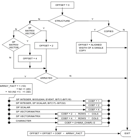
After all groupings are complete, storage assignments are made, with the required base-displacement combinations being generated to properly access the data. The storage addresses assigned refer to the actual data beginning, but for arrayed data types, the base-displacement address includes a negative offset value (COMPOOL variables that are not referenced do not have base-displacement addressing
[image:35.612.89.518.191.646.2]generated). This negative offset value is commonly referred to as an imaginary 0th element.
Figure 3-1 Algorithm for Calculating the 0th Element Offset
OFFSET = 0
STRUCTURE
SP MATRIX/
VECTOR COPIES
DP MATRIX/
VECTOR OFFSET = 2
OFFSET = 4
ARRAYED
OFFSET = ALIGNED WIDTH OF A SINGLE COPY
ARRAY_FACT = 1 (1D) = N2 +1 (2D) = N3 (N2 +1) +1 (3D)
COEF = 4
COEF = 2 ROWS COLS
COEF = 4 ROWS COLS
COEF = (3+MAX_CHAR) /2 COEF = 1
COEF = 2
OFFSET = OFFSET + COEF ARRAY_FACT EXIT
N Y
Y N
Y N
Y
N
N Y
SP INTEGER, BOOLEAN, EVENT, BIT(1)-BIT(16) DP INTEGER, SP SCALAR, BIT(17)- BIT(32)
DP SCALAR
SP VECTOR/MATRIX
DP VECTOR/MATRIX
Example:
DECLARE A SCALAR, B INTEGER,
C CHARACTER(7), D ARRAY(5) DOUBLE; DECLARE E ARRAY(5),
F ARRAY(3,3) VECTOR, G MATRIX;
DECLARE H DOUBLE,
I ARRAY(5,5) INTEGER;
Note that all formal parameters and all AUTOMATIC variables in a RENTRANT PROCEDURE or FUNCTION are based off the stack register (0).
3.1.1.3 Addressing Concepts
This section describes the general addressing rules for data. To the extent possible, data can be directly addressed via some combination of base register and bit
displacement (eleven bits for indexed addressing). This is not possible whenever the data item is a formal parameter other than a simple integer or scalar, or any formal parameter scoped in from an outer to an inner procedure. The skeletal forms given in Section 3.2 assume the most commonly used addressing forms. The rules described here should be superimposed upon these skeletal forms to interpret all possible combinations of operations between operands.
Simple Addressing Forms Simple Variable
OP R,VAR(B)
Simple Aggregate Component (array or vector-matrix)
OP R,VAR+DELTA(X,B)
Simple Integer-Scalar formal parameter
OP R,VAR(0)
Simple Aggregate formal parameter
Alignment Name Location Base Displacement (In Decimal) 0thelement
Halfword B 00002 1 0002 0
Fullword A 00004 1 0004 0
Doubleword H 00008 1 0008 0
Halfword C 0000C 1 000C 0
Halfword I 00011 1 000B -6
Fullword E 0002A 1 0028 -2
Doubleword D 00034 1 0030 -4
Fullword G 00048 1 0046 -2
L B,PAR(0) OP R,DELTA(X,B)
NAME Variable in dereference context
LH B,VAR(B) OP R,DELTA(X,B)
NAME Variable in dereference context (ASSIGN formal parameter)
L B,VAR(B) LH B,0(B)
OP R,DELTA(X,B)
When the DATA REMOTE directive is in effect (see Section 4.0), if register 1 or 3 is loaded with a new base address and used in operation OP as base B, then it will be restored immediately after OP to its original local data pointer value with:
LH B,stack location(0)
However, if the next instruction is a conditional branch, then it will be restored with:
LH B,stack location(0)
SLL B,16
REMOTE Variable
OP@# R,ZCON(X,1)
ZCON DC Z(0,VAR,0)
NAME REMOTE variable in dereference context is basically the same as a REMOTE variable, except the NAME variable is used in place of the ZCON
OP@# R,VAR(X,1)
NAME REMOTE variable in dereference context that lives REMOTE
L@# R,ZCON(X,1)
ST R,stack location(0) OP@# R,stack location(X,0)
REMOTE formal pass-by-reference (address) parameter
OP@# R,stack location(X,0)
Address Passage Addressing Forms
For parameter passing to procedures, functions, and library routines, it is often
necessary to pass address pointers instead of data. The following sequences could be used anywhere the instruction LA appears in the generated code sequence.
Unsubscripted variable:
LA R,VAR(B)
Subscripted variable:
Unsubscripted REMOTE variable:
L R,ZCON(1)4
Subscripted REMOTE variable:
SLL X,<index alignment> or SLL R,<index alignment>
L R,ZCON(1)4
AR R,X
Non-aggregate variable to REMOTE library or to REMOTE parameter in HAL/S procedure or function:
LA R,VAR(B)
OHI R,x'8000' (PASS only) IAL R,x'0800'
Subscripted variable to REMOTE library or to REMOTE parameter in HAL/S procedure or function:
SLL X,<index alignment>
LA R,VAR(X,B)
OHI R,x'8000' (PASS only)
IAL R,x'0000'
Unsubscripted aggregate variable to REMOTE library or to REMOTE parameter in HAL/S procedure or function:
LA R,VAR(B)
OHI R,x'8000' (PASS only)
IAL R,x'0000'
Non-aggregate variable to REMOTE library or to REMOTE parameter in HAL/S procedure or function through a NAME dereference:
LH R,Name Var
IAL R,x'0800' SRA R,1
SRR R,31
OHI R,x'8000' (PASS only)
Subscripted variables to REMOTE library or to REMOTE parameter in HAL/S procedure or function through a NAME dereference:
LH B,Name Var
LA R,<INDEX>(B) SRA R,1
SRR R,31
OHI R,x'8000'(PASS only)
Unsubscripted aggregate variable to REMOTE library or to REMOTE parameter in HAL/S procedure or function through a NAME dereference:
LH R,Name Var
SRA R,1 SRR R,31
OHI R,x'8000' (PASS only)
Subscripted variable to REMOTE library. (stack variable only)
SLL X,<index alignment>
LA R,VAR(X,B)
IAL R,x'0400'
Note that the compiler emits an RLD card that informs the linkage editor to insert the proper CSECT value into the last four bits inserted by the IAL instruction for non-NAME non-stack variables, to conform to the ZCON format.
For stack variable (B=0), this cannot be done because the stack CSECT is undefined at compile time. The '0400' sets the ZCON's C bit which will allow correct address
Indexing:
The computation for all indexing is done as follows. All constant index terms are factored out from the variable terms. The variable terms are computed according to the natural sequence of unwinding aggregate data. The constant terms are similarly computed to form a DELTA. The variable subscript in register X is shifted according to the halfword width of the data being indexed, except for those instructions which perform automatic index alignment. The DELTA is similarly shifted at compile time. If 0<DELTA<2048, it is used in the variable displacement. Otherwise, it is added to X if X is non-zero, or loaded into a newly created X if X is zero (i.e. the subscript contains no variable terms).
3.1.1.4 Condition Codes
The following table lists the allowable relational operations and the resultant condition code - referred to as COND throughout the remainder of this section. Note that the AP-101 conditional branch instructions branch on the "not true" condition.
3.1.1.5 ZCONs and the Calling Mechanisms
Throughout the descriptions of generated code of Section 3.1, branches to other CSECTs (comsub or library) are generally indicated as:
ACALL <routine name>
The actual implementation of this linkage is to go not directly to the named routine, but instead to branch indirectly through a long address constant (ZCON) located in sector 0 of the machine.
When the target of the branch is a compiler-generated CSECT (a COMSUB), the ZCON referenced will be one created during compilation of the COMSUB. The long indirect address will be in a CSECT named #Znnnnnn (see Section 3.2) which will in turn refer to the real code CSECT.
When the target of the branch is a library routine, the ZCON referenced will be one provided with the library. Its name will be #Qnnnnnn and it will in turn refer to the proper library code CSECT. Certain library routines, for reasons of execution speed, are referenced directly by compiler-emitted code without going through a ZCON. These routines are designated in the BANK0 column of the library documentation. This direct addressing requires that these routines reside either in sector zero or in the same sector as the compiler code which references them.
<OP> COND
= 3
¬= 4
< 5
> 6
¬< or >= 2
The use of ACALL in the descriptions implies an external call. In actuality, the instruction generated may be either:
depending on whether the library routine has been designated as PROCEDURE or INTRINSIC type.
Some of the parameter setups show the use of P1, P2, and P3 for parameter registers. The following table shows the actual register values for P1, P2, and P3 depending upon the nature of the library routine (see library documentation for specific details).
When the DATA REMOTE directive is in effect (see Section 4.0), the ACALL will be preceded by the instruction LDM $ZDSECLR to clear the DSE registers, and will be followed by the instruction LDM $ZDSESET to set the DSE registers upon return.
3.1.1.6 The Runtime Stack
The HAL/S-FC compiler system employs a runtime stack mechanism as an integral part of its operation. The stack mechanism is used to provide subroutine linkage areas, temporary work areas, error environments, and to provide reentrancy of code blocks when needed. The actual memory used as a stack space for a given HAL/S process is provided by the flight computer operating system (FCOS). The determination of the size required for a particular stack is made by the flight computer support software linkage editor. The linkage editor determines stack size (and upon special request will create a stack CSECT) from information provided on SYM cards in the modules being link edited. The HAL/S-FC compiler emits the SYM cards as part of its object modules. The runtime library uses a system of macros to generate the properly named DSECTs and SYM entries for stack size computation.
The details of formats and requirements relating to stack generation can be found in the
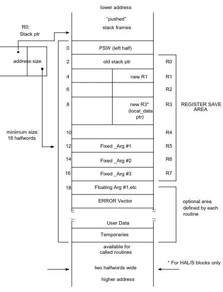
HAL/SDL ICD. That document also contains the detailed description of the "stack frame", that portion of a total stack which is used by an individual subroutine when that subroutine has been invoked. The description of the basic stack frame is reproduced here for reference.
The active stack frame is pointed to by the pointer in register R0. The back link to the previous stack frame is established when a new level is entered. A pointer, NEW R3, is established for any block with a local data area. If a local data area is not present, e.g. in the case of a HAL/S-FC library routine, NEW R3 is set to zero. See Section 3.1.1.7 for a definition of the local data area.
SCAL 0,<routine name> or
BAL 4,<routine name>
P1 P2 P3
Intrinsics 1 2 3
Procedure-P1 used 2 4 7
Figure 3-2 Stack Layout
lower address “pushed” stack frames
PSW (left half) old stack ptr
new R1
new R3* (local_data
ptr)
Fixed _Arg #1
Fixed _Arg #3 Floating Arg #1,etc
ERROR Vector
User Data Temporaries
available for called routines
* For HAL/S blocks only optional area defined by each routine REGISTER SAVE AREA R0 R1 R2 R3 R4 R5 R6 R7 0 2 4 6 8 10 12 14 16 18 minimum size: 18 halfwords address size Stack ptr R0:
two halfwords wide higher address Fixed _Arg #2
3.1.1.7 Local Block Data Areas
During execution of a HAL/S-FC program, certain machine registers have dedicated uses as described in Section 3.1.1.1. In particular, register R3 is a local addressing register which points to the local Block Data Area for the block in execution. These R3 values are saved on the runtime stack as indicated in Section 3.1.1.6. The format of a local Block Data Area is the subject of this section. The HAL/SDL ICD contains the controlling definitions of these areas.
Block Data Areas are created by the compiler and are part of the #Dnnnnnn CSECT generated for a compilation unit. A Block Data Area may exist for any Program,
Procedure, Function, Update Block, or Task. The compiler-emitted code for block entry (as defined in Section 3.1.1.6) loads R3 with the address of the Block Data Area for the block being entered. The format of such an area is shown in the following diagram. Fields
BL 1 Block ID 2
2 XU ONERRS ERRDISP 2
3 TYPE UNUSED RESERVE SVC# 2 ⎫
4 UNUSED RELEASE SVC# 2 ⎬ only required if XU=1
5 LOCK ID 2 ⎭
Field Definition
1. Block ID A 16 bit field uniquely identifying the HAL block. The first 9 bits are a "compilation number" supplied by the user via the
COMPUNIT compiler option. The last 7 bits are a block count generated internally for each new block within a compilation unit. 2. XU EXCLUSIVE/UPDATE flag (1 bit). Set to one if block is either an
UPDATE block or has the EXCLUSIVE attribute.
ONERRS (6 bits). The number of discrete errors for which an ON ERROR statement exists in the block.
ERRDISP (9 bits). The displacement in half words from the stack frame pointer register (R0) to the error vector.
3. TYPE (1 bit). Set to zero for EXCLUSIVE procedure or function. If an UPDATE block, set to one if shared data variables are read only. Set to zero if shared data variables are to be written.
Reserve SVC#
(8 bits). SVC number for the reserve SVC: 15 for a code block
16 for a data area.
4. Release SVC# (8 bits). SVC number for release SVC: 17 for a code block
3.1.1.8 Parameter Passing Conventions for User-Written Routines
To the extent possible, HAL/S parameters are passed via registers. Scalar parameters are passed in floating point registers. All others are passed in general registers. The following rules describe how the registers are designated, and what they contain for each type of parameter.
General purpose registers 5-7 and floating point registers 0, 2, 4 are available for parameter passing. If the supply of registers is exhausted before the parameter list, the balance of the parameters are passed in memory locations. All parameters are located via the stack register (0).
Allocation of general and floating registers is carried on in parallel. If no scalar parameters exist, no floating point registers will contain parameters.
General purpose registers 5 through 7 are automatically contained in the stack beginning at displacement 1210. Floating point registers are not automatically saved, and it is the responsibility of the called program to do so. Storage locations are
reserved in the stack for this purpose as described below. Parameters which cannot be passed in registers are automatically stored in the called procedure's stack by the caller. The allocation of these stack locations is identical to the allocation for floating point values. Note that, unlike ordinary HAL/S variable allocation, parameter allocation is not subject to reordering to minimize alignment conflicts.
The first available stack location is at 1810 off the stack register. All parameters are assigned storage in order starting at this point (the exception being parameters contained in general registers 5 through 7, which are allocated space in the register save area as described above). Any necessary alignment is performed as needed. Arguments are either input type or ASSIGN type (Input types are those whose values will not be changed by the called routine). The actual information which is passed for a particular argument is dependent upon the following factors:
• whether the argument is input or ASSIGN;
• whether the HAL/S data type of the argument is an aggregate (i.e. more than one element, as in a matrix);
• whether the argument has any arrayness or structure copies to be passed; and • whether any arrayness or structure copies are defined via an ARRAY(*) or
-STRUCTURE(*) specification.
5. Lock ID (15 bits). An indicator of which code block or data areas are being used. For a code block this is the address of the
The following table and list show the information which is passed for an argument with particular attributes.
For all cases where auxiliary values are allocated for a single parameter (i.e.
CHARACTER(*) ARRAY or ARRAY(*)), the parameters (up to 3) must be contiguous. Thus, if more pointers are required than registers are available, then the whole
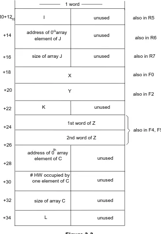
parameter sequence will be pushed into the stack. Example:
P: PROCEDURE(X,Y,I,J,K,Z,C,L); DECLARE SCALAR,X,Y,Z DOUBLE;
DECLARE INTEGER,I,J ARRAY(*),K,L; DECLARE CHARACTER(*) ARRAY(*),C; Data Type
Argument Type
Integer Scalar Bit Character(*) Vector Matrix Structure
Input (no arrayness or copies) 1 2 3 4 5 6 7
ASSIGN (no arrayness or copies)
8 8 8 4 5 6 7
Input or Assign (with arrayness
or copies) 9
†
† If the parameter is declared as ARRAY(*) or -STRUCTURE(*), an additional parameter word is passed containing
the value of the unspecified dimension.
9† 9† 10† 9† 9† 11†
Key Information Passed
1 A halfword or fullword of data.
2 A single or double precision floating point value.
3 Up to 32 bits of data (halfword or fullword depending upon declared size). 4 Address of the max-size byte of the character string.
5 Address of the 0th item in the VECTOR (i.e. 1 item width ahead of the actual vector).
6 Address of the 0th item as if the MATRIX were a VECTOR of length m x n. 7 Address of the first location in the structure as defined by its template. (Note
that item position within a template is subject to compiler reordering unless RIGID is used).
8 Address of the data item.
9 Address of the 0th item of the array.
10 Two items are passed. The first is the address of the 0th array item. The second is the number of halfwords of memory occupied by one character string element (including the halfword containing the max and current size bytes).
Upon entry to this procedure, the stack and registers are as follows:
Figure 3-3
1 word R0+1210
+14
+16
+18
+24
+26
+28 +20
+22
+30
+32
+34
unused
unused unused
unused unused
unused unused
also in R5
also in R6
also in R7
also in F0
also in F2
also in F4, F5
L I
address of 0th array element of J
size of array J
unused K
address of 0th array element of C
size of array C # HW occupied by
one element of C
1st word of Z 2nd word of Z
X
3.1.2 Integer and Scalar Operations
Nomenclature
The register R is any of the available set of accumulators. The terms I, I2, S, and S2 refer to the single and double precision versions of Integer and Scalar values
respectively. It is assumed that any implicit precision or type conversions have been accomplished prior to generating the code sequences shown below.
3.1.2.1 Arithmetic Operators
Integer and scalar arithmetic operators generally employ two operands, denoted as X and Y. X is assumed to be loaded into register Rx unless otherwise noted. If Y is also in a register, it is represented by the form Ry.
Note that the shift operations used in the integer multiplications are required to correctly normalize the result in the proper registers
Certain constant multipliers are optimized to avoid using actual multiply instructions. They are described below.
Operation Type Code Alternate Code
X + Y: I AH Rx,Y AHI Rx,Y†
† Used if Y is a literal.
I2 A Rx,Y AR Rx,Ry
S AE Rx,Y AER Rx,Ry
S2 AED Rx,Y AEDR Rx,Ry
X- Y: Similar to X + Y except that the subtract operator is used (For example, SH in place of AH in the above list). (Multiply)
X Y: I MH Rx,Y MIH Rx,Y†
SLL Rx,15
I2 M Rx,Y MR Rx,Ry
SRDA Rx,1
S ME Rx,Y MER Rx,Ry
S2 MED Rx,Y MEDR Rx,Ry
Operation Type Code Alternate Code
I 2n SLL RI,n,n>1
AR RI,RI,n=1
I2 2n SLL RI,n,n>1
AR RI,RI,n=1
X 1 no code for any type
S 2 AER Rs,Rs
S2 2 AEDR Rs,Rs
X/Y S SER Rx+1,Rx+1 SER Rx+1,Rx+1
DE Rx,Y DER Rx,Ry
X**Y: The exponentiation is performed by subroutine. The patterns shown for I and S are identical to those which will be generated for I2 and S2, except for the obvious differences:
The DED and DEDR instructions are broken on the AP-101S machine. Thus, the compiler emits the following code sequences in place of these instructions:
Operation Type Code Alternate Code
X/Y S2 LER Ra+1,Rx+1 LER Ra+1,Rx+1
LER Ra,Rx LER Ra,Rx
DE RX,Y DER RX,Ry
LER Rb+1,Rx+1 LER Rb+1,Rx+1
LER Rb,Rx LER Rb,Rx
MED Rb,Y MEDR Rb,Ry
SEDR Rb,Ra SEDR Rb,Ra
DE Rb,Y DER Rb,Ry
SEDR RX,Rb SEDR RX,Rb
where the result resides in the Rx,Rx+1 register pair.
In the special case where a double precision result is divided by itself, a double precision "1" is loaded directly into the result register rather than executing the DED/DEDR workaround sequence. The code sequence for this case is:
Operation Type Code
X/X S2 LFLI Rx,1
LFLI Rx+1,0
where the result resides in the Rx,Rx+1 register pair.
I**I LH 5,X ⎫
CVFL 0,5* ⎪
LH 6,Y ⎪
S**I LH 6,Y (see note) ⎬ Argument Setup
LE 0,X ⎪
S**S LE 2,Y ⎪
LE 0,X ⎭
where α and β represent the types of operands X and Y respectively:
Return is in F0 for α of E or D; in R5 for α of H or I.
* if Y operand is a positive integer literal, the CVFL conversion is eliminated and the PWR routine invoked is αPWRH or αPWRI.
Note: Scalar expressions raised to integer literal powers from 1 to 16 are performed in line via repeated multiplication, using the binary powers algorithm. The following examples should serve to illustrate the method.
For type S2, the instruction MEDR is used in place of MER. Two LERs must be used in place of one.
3.1.2.2 Comparison Operators
The full complement of relational operators is allowed for Integer or Scalar operations between single quantities. Only equal or not equal operators are allowed for arrayed comparisons. No logical variables are created by comparisons. Instead, branching to one of two points is used for true/false relations.
Type of X α Type of Y β
Single precision integer ⎫ single precision integer H double precision integer ⎬ E double precision integer I single precision scalar ⎭ single precision scalar E double precision scalar D double precision scalar D single precision integer H*
double precision integer I*
Operation Type Code Alternate Code
X**1: No code generated.
X**2: S MER Rx,Rx
X**3: S LER RT,Rx
MER Rx,Rx
MER RT,Rx
(result in RT)
X**6: S MER Rx,Rx
LER RT,Rx
MER Rx,Rx
MER RT,Tx
(result in RT)
Operation Type Code
+X No code generated
-X I,I2 LACR Rx,Rx
S LECR Rx,Rx
S2 LED Rx,X
Note: For comparisons to the literal 0, the condition code is used directly. If the condition code is not valid, the instruction LR or LER is used to set it.
3.1.2.3 Conversions
Where necessary, conversions are performed in intrinsic or library functions. Some conversions do not require any generation of code.
Integer Conversions
Operation Type Code Alternate Code
X <OP> Y: I CH Rx,Y
BC COND,not-true-label
I2 C Rx,Y CR Rx,Ry
BC COND,not-true-label
S CE Rx,Ry CER Rx,Ry
BC COND,not-true-label
S2 SED Rx,Y SEDR Rx,Ry
BC COND,not-true-label
Operation Code
I TO S LH Rx,X
CVFL Fx,Rx
I TO S2 LH Rx,X
CVFL Fx,Rx
SER Fx+1,Fx+1
I2 TO S L 5,X
ACALL ITOE
I2 TO S2 L 5,X
ACALL ITOD
I,I2 TO BIT No code necessary
I TO CHAR LH 5,X
LA 2,temp-string-area†
† temp-string-area contains converted string.
ACALL HTOC
I2 TO CHAR L 5,X
LA 2,temp-string-area†
ACALL ITOC
I TO I2 SRA Rx,16
Scalar Conversions
3.1.2.4 Assignments
For all assignments, type conversion may take place across the assignment operator. For multiple assignments, the left hand side operands are grouped by data type to minimize the number of conversions performed. The order in which the groups are processed is determined by the following table:
Right Hand Operand Type
Type Ordering I I2 S S2
Character is always performed before any right hand side conversion is performed. Operation Code Alternate Code
S TO I,I2 LE 0,X LER 0,Rx
ACALL αTOβ
S2 TO I,I2 LED 0,X LEDR 0,Rx
ACALL αTOβ
TYPE OF SCALAR α TYPE OF INTEGER β Single Precision E Single Precision H Double Precision D Double Precision I
S,S2 TO BIT Same as for scalar to integer
S TO CHAR LE 0,X
LA 2,temp-string-area†
† temp-string-area contains converted string.
ACALL ETOC
S2 TO CHAR LED 0,X
LA 2,temp-string-area†
ACALL DTOC
S TO S2 LE Rx,X
SER Rx+1,Rx+1
Left Hand
First I I2 S S2
I2 Char Char Char
Char S2 S2 S
S2 S I2 I2
S I I I
The following sequences assume that Rx has already had the required integer or scalar conversions performed as described in Section 3.1.2.3.
Rx is also marked as now containing the value Y. Subsequent usages of Y may use this register in lieu of the copy of Y in memory until such time as the contents of this register are destroyed or a label is generated.
3.1.3 Bit String Operations
3.1.3.1 Bit String Operators
Bit string operators include the following: AND (&), OR (|), and CAT (||). They generally employ two operands, denoted here as X and Y (of lengths Nx and Ny respectively). X is assumed to be loaded into register Rx unless otherwise noted. If Y is also in a register, it is represented as Ry. Note that the & and | operations will pad the bit length of the shorter bit string to the length of the longer bit string.
Operation Type of Y Code
Y = X; I†
† If X is an integer literal of value 0 or-1, then the following code will be generated:
STH Rx,Y
I2 ST Rx,Y
S STE Rx,Y
S2 STED Rx,Y
Y = 0; I ZH Y
Y = -1; I SHW Y
Operation Bit Length Code Alternate Code
X&Y Nx,Ny≤16 NR Rx,Ry NHI Rx,'Y'†
† Used only when Y is a bit literal.
Nx,Ny>16 N Rx,Y NR Rx,Ry
X|Y Nx,Ny≤16 OR Rx,Ry OHI Rx,'Y'†
Nx,Ny>16 O Rx,Y OR Rx,Ry
X||Y Ny≤16 SLL Rx,Ny
OR Rx,Ry
Ny>16 SLL Rx,Ny