warwick.ac.uk/lib-publications
Original citation:
Rajan, Ashwin T., McGordon, Andrew, Widanage, Widanalage Dhammika and Jennings, P. A.
(Paul A.). (2017) Modified electrochemical parameter estimation of NCR18650BD battery
using implicit finite volume method. Journal of Power Sources, 341 . pp. 387-395.
Permanent WRAP URL:
http://wrap.warwick.ac.uk/84467
Copyright and reuse:
The Warwick Research Archive Portal (WRAP) makes this work of researchers of the
University of Warwick available open access under the following conditions.
This article is made available under the Creative Commons Attribution 4.0 International
license (CC BY 4.0) and may be reused according to the conditions of the license. For more
details see: http://creativecommons.org/licenses/by/4.0/
A note on versions:
The version presented in WRAP is the published version, or, version of record, and may be
cited as it appears here.
Short communication
Modi
fi
ed electrochemical parameter estimation of NCR18650BD
battery using implicit
fi
nite volume method
T.R. Ashwin, A. McGordon, W.D. Widanage, P.A. Jennings
*WMG, University of Warwick, Coventry, CV4 7AL, UK
h i g h l i g h t s
Method to parametrise P2D electrochemical model for any cell chemistry.
Numerical expression to calculate OCVþfrom the discharge voltage.
Butler-Volmer equation is modified to a quadratic equation improving the efficiency.
The model results improve on the accuracy reported in the previous literature.
a r t i c l e i n f o
Article history: Received 22 July 2016 Received in revised form 22 September 2016 Accepted 5 December 2016
Keywords: Lithium-ion battery Electrochemical model Pseudo two dimensional model Parameter estimation
a b s t r a c t
The Pseudo Two Dimensional (P2D) porous electrode model is less preferred for real time calculations due to the high computational expense and complexity in obtaining the wide range of electro-chemical parameters despite of its superior accuracy. This paper presents afinite volume based method for re-parametrising the P2D model for any cell chemistry with uncertainty in determining precise electro-chemical parameters. The re-parametrisation is achieved by solving a quadratic form of the Butler-Volmer equation and modifying the anode open circuit voltage based on experimental values. Thus the only experimental result, needed to re-parametrise the cell, reduces to the measurement of discharge voltage for any C-rate. The proposed method is validated against the 1C discharge data and an actual drive cycle of a NCR18650BD battery with NCA chemistry when driving in an urban environment with frequent accelerations and regenerative braking events. The error limit of the present model is compared with the electro-chemical prediction of LiyCoO2battery and found to be superior to the accuracy of the
model presented in the literature.
©2016 The Authors. Published by Elsevier B.V. This is an open access article under the CC BY license (http://creativecommons.org/licenses/by/4.0/).
1. Introduction
Electro-chemical characteristics, and the physical processes in-side a lithium-ion battery can be captured by solving the governing
equations over a porous layout,first proposed by Doyle et al.[1]and
the model is widely known as Pseudo Two Dimensional (P2D) model.
Ageing models available in the literature assume a continuous solvent reduction reaction for the capacity fade. More details can be
found in Ramadass et al.[2]. Many studies proved that ageing of the
cell is strongly coupled with temperature which accelerates the
Solid Electrolyte Interphase (SEI) layer growth [3]. Hence it is
important to solve the full energy equation to capture the thermal
effects by solving an accurate distributed thermal model[4,5]. Very
few studies have looked into the coupled thermal and ageing
studies, for example by Xie et al. [6], Tanim and Rahn [7] and
Ashwin et al.[8].
Inclusion of the above these effects have significantly increased
the computational cost which makes P2D unsuitable for real-time
prediction. More details can be found in Wang et al. [9],
Sub-ramani et al. [10], Haran et al. [11]and a comparative study in
Santhanagopalan et al. [12]. The temperature variation can be
captured by a lumped parameter model[13,14].
Most of the above mentioned models focus on simplifying the chemical process inside a battery by using linear equations which makes the model less accurate in predicting the chemical kinetics. Some studies have looked into reducing the computational
*Corresponding author.
E-mail addresses: [email protected] (T.R. Ashwin), Paul.Jennings@ warwick.ac.uk(P.A. Jennings).
Contents lists available atScienceDirect
Journal of Power Sources
j o u r n a l h o m e p a g e : w w w . e l s e v i e r . c o m/ l o ca t e / j p o w s o u r
http://dx.doi.org/10.1016/j.jpowsour.2016.12.023
requirements by improving the numerical schemes of a P2D model
for example Dao et al. [15] and Lee et al. [16]. The
re-parametrisation of a pseudo two dimensional model requires in-formation about an extensive number of physical parameters, for example, porosity, particle size, solid and electrolyte conductivity
and the diffusion coefficients. A parameter estimation using a
non-linear least squares regression technique is proposed by
Santha-nagopalan et al.[17].
This paper focuses on improving two main complementary as-pects of modelling which need further attention; computational method and re-parametrisation. The computational requirement of a P2D model can be drastically reduced by adopting the implicit formulation presented in this paper. The re-parametrisation helps the modellers to switch between different cell chemistries thereby minimising the extensive measurements of aforementioned phys-ical parameters or in the cases where there is an uncertainty in
electrochemical parameters. Thefinite volume methodology can be
used as a tool to simplify the governing equations and to calculate the positive open circuit voltage of the battery by solving a
quadratic form of Butler-Volmer equation. The modification of
positive Open Circuit Voltage (OCV) had been suggested as a possible solution to parametrise an electrochemical model by
several researchers but was never adapted due to the difficulty in
implementation [17]. This proposed method is applied to
para-metrise a NCR18650BD using known electrochemical values from
SONY 18650 LiyCoO2 chemistry. The model predictions are
vali-dated against the complete drive cycle and 1C discharge voltage. The ageing parameters can be also handled by the an iterative procedure described in the paper.
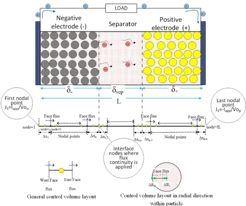
2. Model development&governing equations
The governing equations are discretised over thefinite
volume-finite difference mesh layout as shown inFig. 1.
2.1. Liþions in electrolyte phase
Conservation of Li in electrolyte phase can be represented in a
finite volume-finite difference[18,19]frame work as:
v vtðεeceÞ |fflfflfflfflffl{zfflfflfflfflffl}
Time dependent term
¼V$De;effVce
|fflfflfflfflfflfflfflfflfflfflffl{zfflfflfflfflfflfflfflfflfflfflffl}
Diffusion term
þ1tþ F ðJsþJ1Þ |fflfflfflfflfflfflfflfflfflfflfflffl{zfflfflfflfflfflfflfflfflfflfflfflffl}
Source term
(1)
The boundary condition at the current collector interface:
vce
vx
x¼0
¼0;vce
vx
x¼L ¼0
The time dependent term descretization is given by:
v
vtðεeceÞ ¼
ðεeceÞt ðεeceÞtDt
D
tThe diffusion term descretization is given by:
V$De;effVce
¼
De;effVcexþDx
De;effVcex
D
xThe diffusion term contribution at the first volume near the
negative electrode current collector interface only carries
contri-bution from the east faceflux due to the zero gradient boundary
condition.
2.2. Liþions in the solid phase
v vtcs¼
Ds
r2 v vr
r2v
vrcs
(2)
2.3. Electrolyte phase potential
V$
k
effVf e
þV$
k
effDVInðceÞ
þJ1þJs¼0 (3)
The above equation reduces to Poisson's equation of the following form:
Lv
2f e
v2x ¼K
whereLandKare constants. Thus the solution of this Poisson's
equation can take different values with an added constantfeþQ.
The boundary condition at the negative electrode can be applied as given below:
vfe
vx
x¼0 ¼0
In this formulation, the electrolyte potential at thefirst nodal
point is taken as zero. Thus the second nodal point potential is also zero due the Neumann boundary condition applied at the negative electrode-current collector interface.
2.4. Solid phase potential
V$
s
effVfs
¼ ðJ1þJsÞ (4)
Thus the above equation is a Poisson's equation of the form:
Lv
2f s
v2x ¼K
The solution of the Poisson's equation is of the formfsþQ. The
actual value of the constant (i.e. value ofQ) can be found by solving
the quadratic form of the Butler-Volmer equation (Equation(5)).
Equation (6) gives the value to correct the negative profile and
Equation(7)gives the value to correct the positive profile.
The boundary condition for Equation (2), Equation (3) and
Equation(4)can be found in Ashwin et al.[8].
2.5. Intercalation reaction
The Butler-Volmer equation:
J1¼asio
exp
an
;pFh
RT
exp
an
;pFh
RT (5)
In the above equation let
q
¼exp
a
Fh
RT
where the Butler-Volmer equation reduces to a quadratic equation and the above equation can be rearranged as:
q
2Cq
1¼0whereC¼J1=asioandiois calculated as:
io¼kct
cmaxs csurs ancap s caen
where at thefirst and last nodal point in the anode and cathode, the
current density is proportional to the externally applied current density. Thus:
C¼ Iapp
An;pLn;pasio
The negative part of the solution is neglected and the feasible solution is given by:
q
¼Cþffiffiffiffiffiffiffiffiffiffiffiffiffiffi
C2þ4
p
2
The above equation can be rearranged as:
fsfeU¼FRT
an
;pln
CþpffiffiffiffiffiffiffiffiffiffiffiffiffiffiC2þ4 2
!
The required solid potential at thefirst and last nodal point of
the battery is given by:
fs;n;1¼fe;n;1þUnþ RT
F
an
ln0 @Cnþ
ffiffiffiffiffiffiffiffiffiffiffiffiffiffi C2nþ4
q
2
1
A (6)
fs;p;IL¼fe;p;ILþUpþFRT
ap
ln0 @Cpþ
ffiffiffiffiffiffiffiffiffiffiffiffiffiffi C2pþ4
q
2
1
A (7)
whereCnandCprepresents the constant calculated at the negative
and positive electrode respectively.
The above solid potential can be used to correct the solid
po-tential profile obtained by implicitly solving the Poisson's form of
the solid potential (Equation(4)). Also the negative open circuit
[image:4.595.60.544.60.465.2]voltageUnis common for all batteries with a graphite anode. The
re-parametrisation of a battery can be done using the same formulation for the positive OCV as follows.
The cell voltage is calculated as the difference in solid potential
at thefirst and last control volumesfs;p;ILfs;n;1. In this
formula-tion, the difference of Equation(7)and Equation(6)gives the cell
voltage. Thus the required value offs;p;ILcan be recalculated from
the experimental discharge curve.
fs;p;IL¼Vcell;measuredþfs;n;1
Thus in the above equation, the required value of positive OCV to simulate the discharge characteristics is given by:
Up¼Vcell;measuredþUnþ RT
F
an
ln0 @Cnþ
ffiffiffiffiffiffiffiffiffiffiffiffiffiffi C2nþ4
q
2
1
Afe;p;IL (8)
RT
F
ap
ln0 @Cpþ
ffiffiffiffiffiffiffiffiffiffiffiffiffiffi C2pþ4
q
2
1 A
As mentioned already, the electrolyte potential at thefirst node
fe;n;1 is taken as zero in this formulation tofix the solution of
electrolyte potential. The measured voltageVcell;measuredcan be of
any C-rate. The cell chemistry is absorbed into the Up profile
through the discharge curve.
2.6. Solvent reduction reaction
The capacity fading solvent reduction side reaction:
Js¼ anioseðacfhsÞ (9)
The modification and the assumptions applied to the over
po-tential, can be seen in Ashwin et al.[8]. The total current density at
thefirst nodal point with the ageing model can be recalculated as:
J¼ Iapp
AnLn¼J1þJs (10)
With ageing reaction included, the constant for framing the quadratic form of Butler-Volmer is given by:
C¼ J1
ioas
The calculations involving the solvent reaction side reaction
need to be handled iteratively to find the solid potential atfirst
nodal point. This is because the negative current density is non-linearly coupled to the over potential. In the present model, the current density is found to be converging within ten iterations.
2.7. Equation for variable porosity
vεe
vt ¼asðJ1VLiþþJsVLacÞ (11)
whereVLiþ is the partial molar concentration for intercalation
re-action and VLac is the partial molar concentration for solvent
reduction side reaction. The reversible porosity change gets accel-erated by increasing the partial molar concentration of the
inter-calation reactionVLiwhile the irreversiblefilling due to SEI gets
accelerated by increasing the partial molar concentration for the
side reactionVLac.
2.8. Temperature dependency of properties
Change in temperature will affect the physiochemical property
J
according to:J
¼Jref
exp" EactJ
R 1 Tref 1 T !#
The reference temperature isTref ¼298:15 K and the
activa-tion energy (Eact) for each parameter is listed inTable 1and must
be further parametrised against voltage measured at high
tem-perature. However the values listed inTable 1 hold good upto
35C.
3. Solution method andflow chart
The equations are solved in a sequential way starting with solving the Lithium in electrolyte phase and the Lithium in solid
phase. The electrolyte and solid potential profile can be calculated
by solving the Poisson's form of equation. The quadratic form of the
Bulter-Volmer equation is solved tofind the required solid potential
at thefirst and last nodal points and the solid potential profile is
corrected to the required value from Equation(6)and Equation(7).
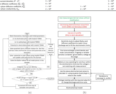
The solution algorithm is explained inFig. 2a. Inner iterations are
provided to enhance coupling between equations. The equations are under-relaxed to handle current variation while applying a dynamic drive cycle. More details of the numerical method can be
found in Ref.[18]and an application of the method in Ashwin et al.
[19] The discretisation of equations form a tri-diagonal form of
matrix which is solved using Tri Diagonal Matrix Algorithm (TDMA).
The above algorithm can be used to calculate the positive elec-trode open circuit potential to re-parametrise the battery. A
detailedflow chart is presented inFig. 2b. The unknown
electro-chemical values are taken from different battery modelling litera-ture for re-parametrisation whereas the measured values are accepted without any change. The uncertainty in measurement is the motivation for taking values from different literature which can cause large error in the conventional P2D modelling with measured
Upprofile. The model is started with an assumed or known positive
open circuit voltage, in this work theUpprofile is from Smith and
Wang [13]. The first observable impact of introducing different
electrochemical parameters from different studies, on the perfor-mance of the battery, is the change in discharge time, the deviation from stoichiometric limits and the variation in the battery voltage. The stoichiometric limits and the running time of the battery can be
corrected by adjusting the particle radius (L) and the solid diffusion
(Ds) coefficient. Adjustments in the side reaction exchange current
density (ios) and the partial molar concentration (VLiþ,VLac) is
needed only if the ageing and variable porosity equations are
solved. A detailed sensitivity study is presented in Section4which
show the battery operating time and stoichiometric limit is within the required range. The optimised set of electrochemical values are used to calculate the required positive open circuit voltage using
Equation(8)for a 1C discharge condition. Now the calculatedUp
will update the voltage limit of the battery within the required
limit. TheUpcalculation is repeated for several iterations to bring
down the RMSE below the required limit. This is due to the fact that
fe;p;IL need few iterations to converge. The OCV for positive
electrode can befitted into the following expression.
Up¼A1e
cB1
C1 2
þA2e
cB2
C2 2
þA3e
cB3
C3 2
þA4
e
cB4
C4 2
þA5e
cB5
C5 2
þA6e
cB6
C6 2
þA7
e
cB7
C7 2
þA8e
cB8
C8 2
(12)
4. Sensitivity analysis of electro-chemical parameters
The electro-chemical parameters for the battery can be obtained from the technical information provided by the manufacturer or from similar literature. In this study, most of the electro-chemical
parameters are taken from the study by Smith and Wang [13]
and Ramadass et al. [2] for a SONY18650 battery. The existing
electro-chemical values need to be further fine tuned to
re-parametrise the model for a NCR18650BD with a different cell chemistry. The cell geometrical parameters are measured in the
laboratory and accepted without modification. Also the porosity
values are summed to unity in both electrodes. The most critical electro-chemical parameters are found to be the particle radius,
diffusion coefficient, partial molar concentration and the exchange
current density for ageing reaction. The particle radius and
diffu-sion coefficient influences the stoichiometric ratio and discharge
time of the battery. Partial molar concentration affects the porous
filling and the side reaction exchange current density affects the
capacity fading of the battery. A detailed analysis forfine-tuning
these parameters within the operating limit is presented in this section.
Fig. 3a shows that decreasing the particle radius in the positive electrode increases the operating time of the battery. The radius of
the particle must be furtherfine tuned to obtain the correct
stoi-chiometry. A smaller particle radius causes an increase in the
vol-ume specific area of the particleas. This has two major effects on
the battery chemical reaction. The current density for intercalation
reactionJ1can increase whereas the radial gradient at the surface of
solid particlevcs=vrdecreases. The radial gradient has more
[image:6.595.41.564.85.146.2]pro-nounced effect in controlling the stoichiometry of the system than Table 1
Activation energies for the Arrhenius correction[13].
Negative electrode Separator Positive electrode
Exchange current densities, Ei0;Ei0þ 3104 3104
Solid phase diffusion coefficient, EDs
act;EDsactþ 4104 2104
Electrolyte phase diffusion coefficient, EDe
act 1104 1104 1104
Electrolyte phase conductivity, Ek
act 2104 2104 2104
[image:6.595.79.534.102.471.2] [image:6.595.40.271.524.625.2]the current density and therefore the overall rate of change of stoichiometry decreases. Thus a decrease in the particle radius decelerates the rate of deposition of solid lithium on the surface of the solid particle.
The solid diffusion coefficient together with the particle radius
can influence the stoichiometry of the battery. The details can be
found inFig. 3b. Hence both parameters must be simultaneously
adjusted to achieve the required performance. The sensitivity of the negative OCV can be further decreased by increasing the stoichi-ometry of the negative electrode for 0% SOC. This reduces the range
of OCV variation in the negative electrode. The modification of the
positive OCV is enough to bring down the error to an acceptable limit.
Another important parameter is the exchange current density
for solvent reduction side reaction (ios). Fig. 3c shows the SEI
thickness with different exchange current densities.Fig. 3d shows
the effect of partial molar concentration over the positive electrode stoichiometry. The run with zero partial molar concentration re-sults in no porosity change and hence the available area for reaction
remains constant (as). Whereas the run with highVLiresults in an
increase in solid porosity (εs) resulting in an increased volume
specific reacting areaas.
The motivation for the above sensitivity study is the difficulty in
measuring the P2D model parameters accurately. Applying the
modifiedUpin the P2D model will correct the operating voltage of
the battery to the required value as follows:
5. Experimental validation of the model
The re-parametrisation of the P2D model for a NCR18650BD battery is completed by modifying the OCV for the positive
elec-trode. A detailed algorithm forUpcalculation is presented inFig. 2b,
and this algorithm is again based on calculations from Equation(8).
The modifiedUp, helps the battery to attain the required operating
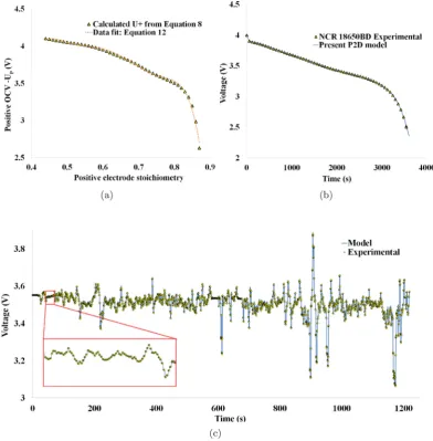
voltage within 0% SOC and 100%SOC limits.Fig. 4a show plot of
modified OCV within the stoichiometric limits. A correlation is then
fitted to this plot and it can be found in Equation(12). It is worth
noting that the correlation 12 is based on the set of
electro-chemical values presented inTable 2. A different set of
electro-chemical values may result in a differentUpcorrelation. This model
does not use the measured value of OCV for any calculation instead
it uses the calculatedUpfrom correlation.
The simulated model is compared with 1C discharge curve as
shown inFig. 4b. The voltage of the battery is recorded at 60 s
in-tervals for 1C measurement. The RMSE for the model compared to
[image:7.595.92.492.64.446.2]the measurement is found to be less than 3:4 mV. Thisfigure only
Fig. 3.Sensitivity analysis of different electro-chemical parameters (a)Discharge profile with different particle size. (b) Discharge profile with different diffusion coefficient. (c) SEI growth with different exchange current density. (d) Positive electrode stoichiometry with different partial molar concentration.
gives a qualitative indication about model behaviour since the 1C
discharge curve is used for the calculation ofUpprofile. Therefore a
more dynamic drive cycle validation is done to test the model behaviour as follows:
Fig. 4c shows the validation of the present model with a
dy-namic drive-cycle voltage profile recorded from a prototype electric
vehicle when driving in an urban environment with frequent ac-celerations and regenerative braking events. The battery is started
with 35% SoC at a constant temperature of 35C. Thus including
some temperature dependency of the validation compared to the parameterisation. The peak current variation is 9.93 A while dis-charging and 10.4 A while dis-charging. This aggressive current pulse takes the battery from 0.01C to 3.5C within a short time step of 1 s. The model is found to agree with the measured values within root
mean square error (RMSE) of 8:9 mV and peak error (PK Error) of
26:0 mV. A comparison of the RMSE and PK Error of the present
model with the literature results of the widely accepted SONY
LiyCoO2model are presented inTable 3. It can be seen that the error
of the current model is lower than that of the SONY battery model for 1C discharge.
6. Conclusion
An implicitfinite volume-finite difference formulation is used to
re-parametrise the P2D model for any cell chemistry with known cathode OCV. The uncertainty in determining exact electrochemical values can be handled in this formulation by modifying the anode OCV. This method, considered as the best to re-parametrise a P2D model for any cell chemistry, has been implemented in this paper
for thefirst time. A numerical expression is derived to calculate
anode OCV based on a simplified quadratic equation for
[image:8.595.106.499.66.466.2]Bulter-Volmer kinetics. Inclusion of this equation in the model is found to reduce the computation time drastically compared to iterative methods. The experimental result needed to re-parametrise the battery, reduces to the measurement of discharge voltage. The computational model is applied to re-parametrise NCR18650BD battery. A sensitivity study is performed in the electrochemical parameters. The model is validated against the full drive cycle and the RMSE and Peak errors are found well within the acceptable limit. The model retains the numerical accuracy whilst comparing with the models presented in the literature. This work proves that the electro-chemical model can be easily parametrised for an any chemistry.
Fig. 4.Electrochemical model predictions of NCR18650BD with modified parameters (a) Calculated positive electrode OCV of NCR18650. (b) Discharge characteristics of NCR18650BD at 25C. (c) Drive cycle validation of NCR18650 model at 35C.
Acknowledgement
This work was funded by Innovate UK through the WMG centre High Value Manufacturing (HVM) Catapult in collaboration with Jaguar Land Rover and TATA Motors European Technical Centre.
Nomenclature
a active surface area per electrode unit volumeð3ε=LÞ
(cm1)
A Electrode plate area (cm2)
c Volume-averaged concentration (mol cm3)
D Diffusion coefficient (cm2s1)
io Exchange current density for intercalation reaction
(A cm2)
ios Exchange current density for solvent reduction reaction
(A cm2)
Iapp Applied current (A)
J1 Reaction current for intercalation reaction (A cm3)
Js Reaction current for solvent reduction reaction (A cm3)
kct Kinetic rate constant for intercalation reaction
L Cell width (cm)
r Radial coordinate (cm)
t Time (s)
U Open Circuit Voltage, OCV (V)
V Cell voltage (V)
Vcell;measured Measured terminal voltage (V)
V Partial molar volume (cm3mol1
)
Greek symbols
a
Charge-transfer coefficientε Volume fraction of domain
L Particle radius (cm)
k
Conductivity of electrolyte (S cm1)k
D Diffusivity (A cm1)c
Stoichiometric ratios in the electrodes
Solid phase conductivity (S cm1)f
Volume averaged potential (V)Superscript&subscript
1 First Cartesian or Radial control volume
IL Last Cartesian control volume
rl Last Radial control volume
e Electrolyte phase
eff Effective
max Maximum
n;p Negative and positive electrode
s Solid phase
sur Surface quantity
References
[1] M. Doyle, T.F. Fuller, J. Newman, J. Electrochem. Soc. 140 (1993) 1526e1533. [2] P. Ramadass, B. Haran, P.M. Gomadam, R. White, B.N. Popov, J. Electrochem.
Soc. 151 (2004) A196eA203.
[3] J. Groot, M. Swierczynski, A.I. Stan, S.K. Kær, J. Power Sources 286 (2015) 475e487.
[image:9.595.32.564.85.314.2][4] L. Cai, R.E. White, J. Power Sources 196 (2011) 5985e5989. [5] M. Guo, R.E. White, J. Power Sources 221 (2013) 334e344. Table 2
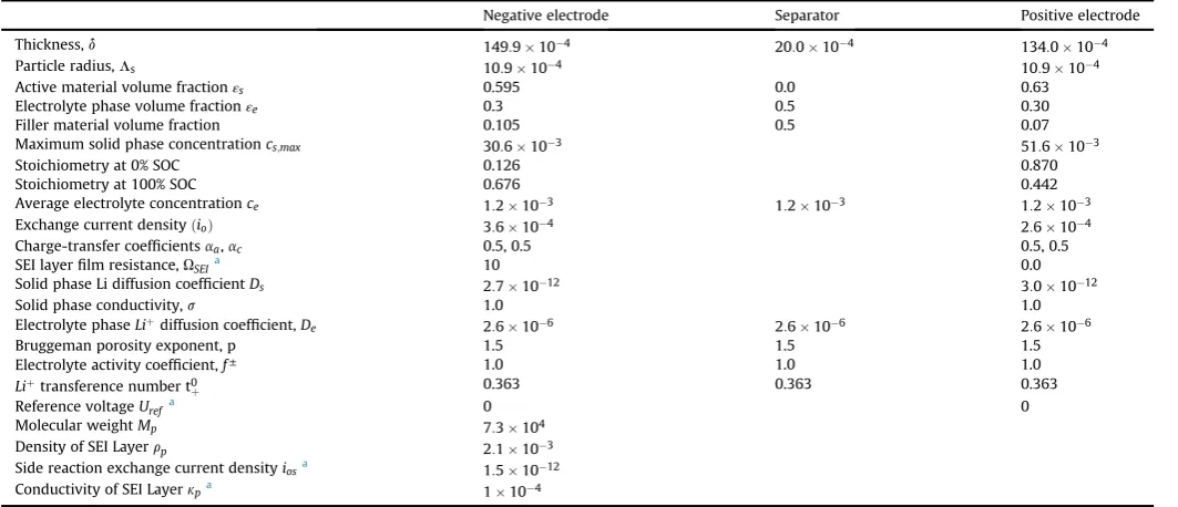
Optimised electrochemical parameters for NCR18650BD battery.
Negative electrode Separator Positive electrode
Thickness,d 149:9104 20:0104 134:0104
Particle radius,Ls 10:9104 10:9104
Active material volume fractionεs 0.595 0.0 0.63
Electrolyte phase volume fractionεe 0.3 0.5 0.30
Filler material volume fraction 0.105 0.5 0.07
Maximum solid phase concentrationcs;max 30:6103 51:6103
Stoichiometry at 0% SOC 0.126 0.870
Stoichiometry at 100% SOC 0.676 0.442
Average electrolyte concentrationce 1:2103 1:2103 1:2103
Exchange current densityðioÞ 3:6104 2:6104
Charge-transfer coefficientsaa,ac 0.5, 0.5 0.5, 0.5
SEI layerfilm resistance,USEIa 10 0.0
Solid phase Li diffusion coefficientDs 2:71012 3:01012
Solid phase conductivity,s 1.0 1.0
Electrolyte phaseLiþdiffusion coefficient,D
e 2:6106 2:6106 2:6106
Bruggeman porosity exponent, p 1.5 1.5 1.5
Electrolyte activity coefficient,f± 1.0 1.0 1.0
Liþtransference number t0
þ 0.363 0.363 0.363
Reference voltageUrefa 0 0
Molecular weightMp 7:3104
Density of SEI Layerrp 2:1103
Side reaction exchange current densityiosa 1:51012
Conductivity of SEI Layerkpa 1104
aAssumed values.
Table 3
Error comparison of different models for 1C discharge and the drive cycle at 30% SoC and 35oC.
RMSE (mV) PK Error (mV) Calculation time (s)
Electro-chemical model NCR18650BD 2.20 3.01 38
Electro-chemical model LiyCoO2a 3.04 4.02 56
Electro-chemical model NCR18650BDb 8.9 26.0
aAshwin et al.[8]. bFull drive cycle validation.
[image:9.595.38.553.366.410.2][6] Y. Xie, J. Li, C. Yuan, J. Power Sources 248 (2014) 172e179. [7] T.R. Tanim, C.D. Rahn, J. Power Sources 294 (2015) 239e247. [8] T. Ashwin, Y.M. Chung, J. Wang, J. Power Sources 328 (2016) 586e598. [9] C. Wang, W. Gu, B. Liaw, J. Electrochem. Soc. 145 (1998) 3407e3417. [10] V.R. Subramanian, J.A. Ritter, R.E. White, J. Electrochem. Soc. 148 (2001)
E444eE449.
[11] B.S. Haran, B.N. Popov, R.E. White, J. Power Sources 75 (1998) 56e63. [12] S. Santhanagopalan, Q. Guo, P. Ramadass, R.E. White, J. Power Sources 156
(2006) 620e628.
[13] K. Smith, C.-Y. Wang, J. Power Sources 160 (2006) 662e673.
[14] B. Wu, V. Yufit, M. Marinescu, G.J. Offer, R.F. Martinez-Botas, N.P. Brandon, J. Power Sources 243 (2013) 544e554.
[15] T.-S. Dao, C.P. Vyasarayani, J. McPhee, J. Power Sources 198 (2012) 329e337. [16] J.L. Lee, A. Chemistruck, G.L. Plett, J. Power Sources 220 (2012) 430e448. [17] S. Santhanagopalan, Q. Guo, R.E. White, J. Electrochem. Soc. 154 (2007)
A198eA206.
[18] S. Patankar, Numerical Heat Transfer and Fluid Flow, CRC Press, 1980. [19] T. Ashwin, G. Narasimham, S. Jacob, Int. J. Heat Mass Transf. 54 (2011)