warwick.ac.uk/lib-publications
Original citation:
Cheng, Fen, Zhang, Shun, Li, Zan, Chen, Yunfei, Zhao, Nan, Yu, F. Richard and Leung, Victor C.
M. (2018) UAV trajectory optimization for data offloading at the edge of multiple cells. IEEE
Transactions on Vehicular Technology .
Permanent WRAP URL:
http://wrap.warwick.ac.uk/99464
Copyright and reuse:
The Warwick Research Archive Portal (WRAP) makes this work by researchers of the
University of Warwick available open access under the following conditions. Copyright ©
and all moral rights to the version of the paper presented here belong to the individual
author(s) and/or other copyright owners. To the extent reasonable and practicable the
material made available in WRAP has been checked for eligibility before being made
available.
Copies of full items can be used for personal research or study, educational, or not-for profit
purposes without prior permission or charge. Provided that the authors, title and full
bibliographic details are credited, a hyperlink and/or URL is given for the original metadata
page and the content is not changed in any way.
Publisher’s statement:
© 2018 IEEE. Personal use of this material is permitted. Permission from IEEE must be
obtained for all other uses, in any current or future media, including reprinting
/republishing this material for advertising or promotional purposes, creating new collective
works, for resale or redistribution to servers or lists, or reuse of any copyrighted component
of this work in other works.
A note on versions:
The version presented here may differ from the published version or, version of record, if
you wish to cite this item you are advised to consult the publisher’s version. Please see the
‘permanent WRAP url’ above for details on accessing the published version and note that
access may require a subscription.
UAV Trajectory Optimization for Data Offloading at the Edge
of Multiple Cells
Fen Cheng, Shun Zhang,
Member, IEEE,
Zan Li,
Senior Member, IEEE,
Yunfei Chen,
Senior Member, IEEE,
Nan Zhao,
Senior Member, IEEE,
F. Richard Yu,
Fellow, IEEE,
and Victor C. M. Leung,
Fellow, IEEE
Abstract—In future mobile networks, it is difficult for static base stations (BSs) to support the rapidly increasing data services, especially for cell-edge users. Unmanned aerial vehicle (UAV) is a promising method that can assist BSs to offload the data traffic, due to its high mobility and flexibility. In this paper, we focus on the UAV trajectory at the edges of three adjacent cells to offload traffic for BSs. In the proposed scheme, the sum rate of UAV served edge users is maximized subject to the rate requirements for all the users, by optimizing the UAV trajectory in each flying cycle. The optimization is a mixed-integer non-convex problem, which is difficult to solve. Thus, it is transformed into two convex problems, and an iterative algorithm is proposed to solve it by optimizing the UAV trajectory and edge user scheduling alternately. Simulation results are presented to show the effectiveness of the proposed scheme.
Index Terms—Data offloading, interference avoidance, trajec-tory optimization, unmanned aerial vehicle (UAV).
I. INTRODUCTION
Future mobile networks aim to realize larger coverage, support more devices, and achieve higher throughput to meet the explosive by increasing demand for data [1], [2]. However, the traditional cellular networks are deployed typically with static base stations (BSs), which have several challenges. First, the pressure on BSs is becoming more and more serious with increasing data traffic. Moreover, edge users often suffer from poor quality of service (QoS) due to long distances from BSs. As a result, there has been growing interest in hybrid cellular networks assisted by unmanned aerial vehicle (UAV) as mobile BSs [3], due to their mobility and flexibility.
Manuscript received October 30, 2017; revised January 30, 2018; accepted March 1, 2018. This research was supported in part by the open research fund of State Key Laboratory of Integrated Services Networks under Grant ISN19-02, the Fundamental Research Funds for the Central Universities under DUT17JC43, the Xinghai Scholars Program, and the National Natural Science Foundation of China (NSFC) under Grant 61631015, 61771089 and 61671101. The associate editor coordinating the review of this paper and approving it for publication was K. Adachi.(Corresponding author: Nan Zhao.)
F. Cheng and N. Zhao are with the School of Inform. and Commun. Eng., Dalian University of Technology, Dalian, Liaoning, 116024, P. R. China, and also with the State Key Laboratory of Integrated Services Networks, Xidian University, Xi’an, 710071, P. R. China (email: [email protected], [email protected]).
S. Zhang and Z. Li are with the State Key Laboratory of Integrated Services Networks, Xidian University, Xi’an, 710071, P. R. China. (Email: [email protected], [email protected]).
Y. Chen is with the School of Engineering, University of Warwick, Coventry CV4 7AL, U.K. (e-mail: [email protected]).
F.R. Yu is with the Department of Systems and Computer Engi-neering, Carleton University, Ottawa, ON, K1S 5B6, Canada (email: [email protected]).
V.C.M. Leung is with the Department of Electrical and Computer Engineer-ing, the University of British Columbia, Vancouver, BC, V6T 1Z4, Canada (email: [email protected]).
UAVs can not only help ground BSs to offload data traffic, but also enhance the channel conditions of edge users by flying close to them to provide line-of-sight (LOS) links [4]. Furthermore, there have been many other wireless applications for UAVs, such as mobile relays [5], [6], mobile computing cloudlets [7],etc. Some important works have been conducted in UAV-aided mobile networks recently [8]–[18]. In [8], Bor-Yalinizet al. investigated the 3-D placement problem of the static UAV to maximize the covered number of users. The 2-D placement optimization algorithm of multiple UAVs was proposed by Lyu et al. in [9], to minimize the number of UAVs that can cover all the ground terminals. Mozaffari et al. maximized the downlink coverage significantly by opti-mizing 3D deployment of UAVs with directional antennas in [10]. In [11], the sum rate was effectively maximized by Mozaffari et al. through appropriately adjusting the UAV’s altitude based on the density of D2D users. In [12], Chen et al. deployed cache-enabled UAVs in the cloud radio access networks to optimize the quality of experience for mobile users. In [13], a caching UAV assisted secure transmission scheme in small-cell networks based on interference alignment was proposed by Cheng et al.. The energy trade-off problem in the ground-to-UAV communications was studied by Yang et al. via trajectory optimization in [14]. In [15], Lyu et al. maximized the minimum rate of all mobile terminals by jointly optimizing the UAV’s circular trajectory radius, user partitioning and bandwidth allocation. The UAV trajectory optimization is difficult to solve due to the non-convexity, and some pioneering work was done by Zeng et al. to first utilize successive convex optimization to solve the problem effectively [16] and [17]. In [18], some fundamental research was done by Wuet al., in which multiple UAVs’ trajectories were optimized jointly with the user scheduling and power allocation, to maximize the minimum rate of all the mobile users. Nevertheless, no ground BSs were considered in [18], but the interference between BSs and UAV will affect the QoS of mobile users severely, which should be properly avoided by optimizing the UAV trajectory.
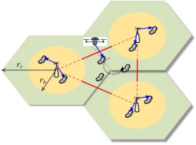
Fig. 1. UAV data offloading at the edge of three adjacent cells.
simulation results are presented to show the effectiveness of the proposed UAV trajectory scheme with the existence of multiple BSs.
Notation: Italic letteraorAdenotes that it is a scalar, and bold-face lower-case letter a and bold-face upper-case letter Adenote a vector and a matrix, respectively.aT represents its
transpose and ∥a∥ denotes its Euclidean norm.
II. SYSTEMMODEL ANDPROBLEMFORMULATION A. System Model
Consider a cellular network with three adjacent BSs1 and a single UAV jointly serving the ground users, as shown in Fig. 1. The users are randomly distributed in each hexangular cell with radius rc. Each BS is located at the center of its cell.
To guarantee the QoS of edge users, each BS only serves the users within the distance rb,rb≤
√
3
2 rc, while the remaining
edge users of three adjacent cells served by the UAV. The sets of users served by themth BS and the UAV are denoted as Im and K, respectively, m = 1,2,3. Each BS has M
antennas, while the UAV and each mobile user have a single antenna [4]. Assume that there is no interference between the users served by different BSs, due to the long distance. The Cartesian coordinate system is considered, where the horizontal coordinates of the mth BS, the ith user served by themth BS and thekth user served by the UAV are expressed as Gm,Wmi andWk, respectively.
We assume that the UAV flies at a fixed altitude H above ground within each cycle T, which can be divided into N
equivalent time slots. The value of N should be properly chosen to guarantee that the UAV’s location is approximately unchanged within each slot. H should be set as small as possible with the safety considerations such as terrain or building avoidance. Then, the horizontal location of the UAV at the nth time slot can be denoted as q[n] = [x[n], y[n]]T,
n = 1,2, ..., N. The maximum UAV speed is denoted asV, and thus, the UAV trajectory should satisfy
q[1] =q[N], (1)
||q[n+ 1]−q[n]||2≤
(
V T N
)2
, n= 1,2,· · ·, N−1. (2)
1The proposed scheme can be easily extended to general cases with more
adjacent cells considered.
The channel power gain from the UAV to the user located atWl (l=mior k) is assumed to follow the free-space path
loss model due to LOS channel as
hul=ρ0 (
H2+∥q[n]−Wl∥ 2)−1
, n= 1,2,· · ·, N, (3) where ρ0 is the reference channel power atd0 = 1 m. The
channel power gain from the mth BS to the ith user served by the BS can be denoted as
hmi=α0h [i] mmv
[i] m
2(
∥Gm−Wmi∥ 2)−3/2
, (4) whereα0 is the reference terrestrial channel power gain, the
path loss exponent of terrestrial channels is assumed to be 3, andh[mmi] accounts for the small-scale channel fading from the
mth BS to theith user served by the BS.v[mi] is the precoding
vector for theith user served by themth BS, which is designed to eliminate the interference between users served by the BS.
The UAV offloading schedule is defined as
αk[n] ={0,1},∀k∈ K,∀n, (5)
whereαk[n] = 1(or 0) indicates that the UAV serves (or does
not serve) thekth edge user in thenth time slot. Assume that the UAV can serve at most one edge user in each time slot, which yields the constraint as
∑
k∈Kαk[n]≤1, ∀n. (6)
B. Problem Formulation
According to the system model in Section II-A, the average rate of the ith user served by themth BS (m= 1,2,3) over
N time slots can be expressed as
R[mi]=
1
N
N ∑
n=1
log2 (
1 + P hmi
puhumi+σ2 )
,∀i∈ Im, (7)
whereP andpu are the transmit power of each BS and the
UAV, respectively, andσ2is the additive white Gaussian noise power.
The average rate of the kth edge user served by the UAV overN time slots can be expressed as
R[k]= 1
N
N ∑
n=1
αk[n] log2 (
1 + puhuk
Iu[k]+σ2 )
,∀k∈ K, (8)
where
Iu[k]=
3 ∑
m=1
P ρ0
∥Gm−Wk∥2 (
∑
i∈Im h[muk] v
[i] m
2)
(9)
is the interference to thekth edge user served by UAV from the BSs. h[muk] accounts for small-scale channel fading from themth BS to thekth edge user served by the UAV. Thus, the sum rate of users served by the UAV can be written as
Rsumu =∑
k∈KR
[k]. (10)
rate requirement at each user by jointly optimizing the edge user schedulingA={αk[n],∀k,∀n}and UAV trajectoryQ=
{q[n],∀n}. The optimization problem can be formulated as
max
A,Q R sum
u (11a)
s.t. R[k]≥η, ∀k∈ K, (11b)
R[mi] ≥γ, ∀i∈ Im,∀m∈ {1,2,3}, (11c)
(1),(2),(5),(6). (11d) III. LOW-COMPLEXITYSOLUTION
Problem (11) is difficult to solve as it is a mixed-integer non-convex problem. To make it tractable, the binary variables in (5) are relaxed into continuous variables as
0≤αbk[n]≤1,∀k∈ K,∀n. (12)
Then, an efficient iterative algorithm is proposed. In each iteration, the edge user scheduling is first optimized for fixed UAV trajectory, and then, UAV trajectory is optimized with the optimized user scheduling in the first step.
A. Edge User Scheduling Optimization
For any given UAV trajectory Q, the edge user scheduling optimization in (11) can be rewritten as follows, with αk[n]
relaxed into continuous αbk[n].
max
A R sum
u (13a)
s.t. R[k]≥η, ∀k∈ K, (13b)
(6),(12). (13c)
Problem (13) is easy to solve by applying classical optimiza-tion methods, because it is a standard linear programming.
B. UAV Trajectory Optimization
For any given edge user scheduling A, the UAV trajectory optimization in (11) can be rewritten as
max
Q R sum
u (14a)
s.t. R[k]≥η, ∀k∈ K, (14b)
R[mi] ≥γ, ∀i∈ Im,∀m∈ {1,2,3}, (14c)
(1),(2). (14d)
Note that (14) is not a convex optimization problem due to the non-convex objective function and the non-convex constraints in (14b) and (14c), which is difficult to solve. Therefore, a successive convex optimization technique is applied to obtain the optimal solution approximately, which can be derived in Theorem 1. To obtain Theorem 1, Lemma 1 and Lemma 2 are first introduced to make constraints (14b) and (14c) convex.
Lemma 1: The non-convex constraint (14b) can be trans-formed into a convex one as
1
N
N ∑
n=1 b
αk[n]Rb [k]
ulb[n]≥η, ∀k∈ K, (15)
where
b
R[ulbk][n] =−Ckr[n](∥q[n]−Wk∥2−∥qr[n]−Wk∥2 )
+Drk[n],(16)
Ckr[n] =
(Iu[k]+σ2)puρ0 ((
Iu[k]+σ2
)
(H2+∥qr[n]−W k∥2)
)2log2(e)
1 +( puρ0
I[uk]+σ2
)
(H2+∥qr[n]−Wk∥2)
≥0, (17)
Dkr[n] = log2
1+( puρ0
Iu[k]+σ2 )(
H2+∥qr[n]−W k∥
2)
≥0.(18)
Proof:First, we can defineRb[uk][n]as
b
Ru[k][n] = log2
1+( puρ0
Iu[k]+σ2 ) (
H2+∥q[n]−W k∥
2) . (19)
It is important to observe thatRb[uk][n]is convex with respect
to ∥q[n]−Wk∥2, although it is not concave with respect to
q[n]. Then, we assume thatQr={qr[n],∀n}is the trajectory
of UAV in the rth iteration. It is known that the first-order Taylor series expansion of a convex function provides a lower bound. Thus, with given UAV trajectoryQrin therth iteration, we have (20) in the(r+ 1)th iteration as follows.
b
R[uk][n]≥ −Ckr[n](q[n]−Wk∥2−qr[n]−Wk∥2 )
+Drk[n]
=Rb[ulbk][n], (20)
whereCr
k[n] andD r
k[n] are constants as in (17) and (18).
Therefore, the non-convex constraint (14b) can be approxi-mated as (15). Since Rb[ulbk][n]is concave with respect toq[n], the constraint (15) is convex with respect toq[n].
Lemma 2: By using the successive convex optimization technique and introducing slack variables S={Smi[n],∀i ∈
Im,∀m∈ {1,2,3},∀n}, the non-convex constraint (14c) can
be transformed into a convex one as
1
N
N ∑
n=1 (
log2(puρ0+(σ2+P hmi)(H2+Smi[n]))−Rbubmi[n] )
≥γ, (21)
where
b
Rmiub[n] =Emir [n] (
∥q[n]−Wk∥ 2
−∥qr[n]−Wk∥ 2)
+Fmir [n], (22)
Emir [n] =
σ2log2(e)
puρ0+σ2 (
H2+∥qr[n]−W mi∥
2) ≥0, (23)
Fmir [n] = log2
(
puρ0+σ2 (
H2+∥qr[n]−Wmi∥ 2))
. (24) In addition, Smi[n] should satisfy
Smi[n]≤∥qr[n]−Wmi∥ 2
+2 (qr[n]−Wmi) T
(q[n]−qr[n]).(25) Proof: First, we rewrite the left-hand-side of the con-straint (14c) as a difference of two functions
log2
(
1 + puP hρ0 mi
H2+∥q[n]−Wmi∥2 +σ2
)
=log2 (
puρ0+ (
σ2+P hmi )(
H2+∥q[n]−Wmi∥ 2))
−Rbmi[n],
(26)
where
b
Rmi[n] = log2 (
puρ0+σ2 (
H2+∥q[n]−Wmi∥ 2))
It is easy to observe thatRbmi[n]is concave with respect to
∥q[n]−Wmi∥ 2
, although it is not convex with respect toq[n]. Recall that the first-order Taylor series expansion of a concave function is its upper bound. Thus, with given UAV trajectory Qr in therth iteration, we have the following equation in the
(r+ 1)th iteration.
b
Rmi[n] ≤Emir [n] (
∥q[n]−Wk∥2−∥qr[n]−Wk∥2 )
+Fmir [n]
=Rbubmi[n], (28)
whereEmir [n]andFmir [n]are constants expressed as (23) and (24). Obviously,Rbub
mi[n] is convex with respect toq[n].
On the other hand, the first term (i.e., minuend) in (26) is concave with respect to ∥q[n]−Wmi∥2. Thus, we can
intro-duce slack variables S = {Smi[n] ≤ ∥q[n]−Wmi∥2,∀i ∈
Im,∀m ∈ {1,2,3},∀n} to approximatively rewrite the
con-strain (14c) as (21) for all i ∈ Im, m∈ {1,2,3}. Then, the
minuend function in (21) is concave with respect to Smi[n].
Thus, the constrain (21) is jointly convex with respect toq[n]
andSmi[n].
Nevertheless, the introduction of relaxation variablesSmi[n]
adds a new constraint to the optimization problem in (14) as
Smi[n]≤ ∥q[n]−Wmi∥ 2
,∀i∈ Im,∀m∈ {1,2,3},∀n. (29)
Similarly, since∥q[n]−Wmi∥ 2
is convex with respect toq[n], its lower bound can be obtained by using the first-order Taylor series expansion, i.e., with given UAV trajectory Qr, in the
(r+ 1)th iteration, we have
∥q[n]−Wmi∥ 2
≥ ∥qr[n]−Wmi∥ 2
+2 (qr[n]−Wmi) T
(q[n]−qr[n]). (30)
Then, we can obtain (25), which is convex quadratic.
Based on Lemma 1 and Lemma 2, we can transform (14) into a convex problem as in Theorem 1.
Theorem 1:With given UAV trajectoryQrobtained in the
rth iteration, (14) can be approximated as (31) in the(r+ 1)th iteration, which is convex.
max
Q,S
∑
k∈K (
1
N
N ∑
n=1 b
αk[n]Rb [k] ulb[n]
)
(31a)
s.t.(15),(21),(25),(1),(2). (31b)
Proof:Based on Lemma 1, the lower bound ofRsum u can
be obtained as
Rsumu ≥∑
k∈K (
1
N
N ∑
n=1 b
αk[n]Rb [k] ulb[n]
)
. (32)
Since Rb[ulbk][n]is concave with respect toq[n], the right-hand-side of inequation (32) is concave with respect toq[n]. Thus, the maximization of the lower bound of Rsumu is convex. In addition, the constraints in (31b) are convex or linear according to Lemma 1 and Lemma 2. Therefore, (31) is a convex optimization problem, which can be solved by using classical optimization methods.
C. Iterative Algorithm
Based on the results above, we can divide the entire optimization variables in problem (11) into two steps, i.e., A and Q, which can be optimized by solving the problem (13) and (31) alternately. The whole iterative algorithm can be summarized as Algorithm 1, which is guaranteed to converge quickly with a sub-optimal solution obtained. The compu-tational complexity of (11) can be reduced significantly by Algorithm 1 due to the convexity of (13) and (31).
Algorithm 1 Iterative algorithm for problem (11)
1: Initialize Q0, letr= 0. 2: repeat
3: Solve convex problem (13) with givenQr, and denote the solution as Ar+1.
4: Solve convex problem (31) with givenAr+1, and denote the solution as Qr+1.
5: Update r=r+ 1.
6: until The increase of the objective function is below a predefined threshold ϵ >0.
After Algorithm 1, the variables αbk[n] can be discretized
into binary ones as
αk[n] = {
1, αbk[n]≥0.5,
0, αbk[n]<0.5.
(33)
Remark:In the proposed UAV trajectory scheme, the UAV should fly close to its served users to improve their perfor-mance. At the same time, the UAV should stay away from the BS served users, to avoid generating interference to them. Therefore, the UAV trajectory should be traded off to optimize the QoS of edge users, which will be shown through simulation in Section IV.
IV. SIMULATIONRESULTS ANDDISCUSSIONS In this section, simulation results are presented to demon-strate the performance of the proposed trajectory optimization scheme. In the simulation, we set rc = 1 km, rb = 500 m,
H = 100, ρ0 =−60 dB, α0 =−40 dB, σ2 = −110 dBm,
V = 50 m/s, T = 120 s,P =pu = 0.1 W, γ= 1.5bit/s/Hz,
andη = 0.5 bit/s/Hz. Two cases are considered for different locations of the 2nd user served by the 2nd BS. Compared to Case I, the user location W22 is changed to be very close
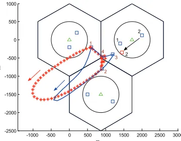
to the edge area in Case II. In this paper, the UAV trajectory is optimized to maximize the sum rate (MSR) of edge users with additional constraints, and the simulations results of the two cases are shown in Fig. 2. The average sum rate and transmission rate of each edge user are also compared in the first two rows of Table I for these two cases, in bit/s/Hz. On the other hand, we can also maximize the minimum average rate (MMR) of all the edge users with the same constraints in (11), which can be solved similarly to our proposed solution in Section III. The corresponding simulation results of the MMR scheme are shown in Fig. 3 and last two rows of Table I.
-1000 -500 0 500 1000 1500 2000 2500 3000 -2500
-2000 -1500 -1000 -500 0 500 1000
m
m
1 2
4 3
2
2
[image:6.612.83.263.52.192.2]1
Fig. 2. UAV trajectory optimization in the MSR scheme. Trajectory of Case I is blue, while Case II is red. BSs are marked by green△. Users are marked by blue, and the2nd user of the2nd BS in Case II is marked by red.
-1000 -500 0 500 1000 1500 2000 2500 3000 -2500
-2000 -1500 -1000 -500 0 500 1000
m
m
2 1
2
1
2 4
3
Fig. 3. UAV trajectory optimization in the MMR scheme. The curves and points are marked similarly to those in Fig. 2.
optimizing the UAV trajectory with the rate requirements of all the users satisfied. However, for some edge users, e.g., the 4th user, their average transmission rate is as low as the rate threshold (0.5 bit/s/Hz). One the other hand, for the MMR scheme, the minimum transmission rate of the edge users can be optimized, and thus, the fairness between users can be guaranteed. Nevertheless, the sum rate of the MMR scheme is sacrificed, which is much lower than that of the MSR scheme. In addition, we can see that when the 2nd user served by the 2nd BS moves to the edge area in Case II, the optimized trajectory will move far away from this user, to avoid strong interference to it and guarantee its QoS. Correspondingly, the performance of both the schemes in Case I is better than that in Case II, due to the fact that the interference will become stronger when the users served by UAV and BSs become closer, no matter which optimization is taken.
V. CONCLUSIONS
In this paper, the UAV trajectory optimization for data offloading in the edge area of multiple cells has been re-searched. In the proposed scheme, three adjacent cells were considered, and the trajectory was optimized to maximize the sum rate of edge users by avoiding the interference between BSs and UAV, with the rate requirements of all the mobile users satisfied. To solve this non-convex problem, it was first transformed into two convex subproblems, and then, an effective algorithm was proposed to calculate the solutions
TABLE I
RATECOMPARISON OFEDGEUSERS INMSRANDMMR SCHEMES.
Case Sum rate User 1 User 2 User 3 User 4
MSR-Case I 4.5494 0.5000 2.3587 1.1849 0.5059 MSR-Case II 2.9971 0.5000 1.4970 0.5000 0.5000 MMR-Case I 3.4772 0.8693 0.8693 0.8693 0.8693 MMR-Case II 2.9532 0.7383 0.7383 0.7383 0.7383
alternately. Simulation results were presented to show the effectiveness of the proposed scheme in UAV trajectory design. In our future work, we will continue to focus on the multi-UAV scenario of trajectory optimization for data offloading.
REFERENCES
[1] S. Sun, K. Adachi, P. H. Tan, Y. Zhou, J. Joung, and C. K. Ho, “Heterogeneous network: An evolutionary path to 5G,” in APCC’15, pp. 174–178, Kyoto, Japan, Oct. 2015.
[2] J. G. Andrews, S. Buzzi, W. Choi, S. V. Hanly, A. Lozano, A. C. K. Soong, and J. C. Zhang, “What will 5G be?,” IEEE J. Sel. Areas Commun., vol. 32, no. 6, pp. 1065–1082, Jun. 2014.
[3] L. Gupta, R. Jain, and G. Vaszkun, “Survey of important issues in UAV communication networks,”IEEE Commun. Surv. Tuts., vol. 18, no. 2, pp. 1123–1152, 2nd Quart. 2016.
[4] Y. Zeng, R. Zhang, and T. J. Lim, “Wireless communications with un-manned aerial vehicles: Opportunities and challenges,”IEEE Commun. Mag., vol. 54, no. 5, pp. 36–42, May 2016.
[5] P. Zhan, K. Yu, and A. L. Swindlehurst, “Wireless relay communications with unmanned aerial vehicles: Performance and optimization,” IEEE Trans. Aerosp. Electron. Syst., vol. 47, no. 3, pp. 2068–2085, Jul. 2011. [6] D. Orfanus, E. P. de Freitas, and F. Eliassen, “Self-organization as a supporting paradigm for military UAV relay networks,”IEEE Commun. Lett., vol. 20, no. 4, pp. 804–807, Apr. 2016.
[7] S. Jeong, O. Simeone, and J. Kang, “Mobile edge computing via a UAV-mounted cloudlet: Optimization of bit allocation and path planning,” IEEE Trans. Veh. Technol., to appear.
[8] R. I. Bor-Yaliniz, A. El-Keyi, and H. Yanikomeroglu, “Efficient 3-D placement of an aerial base station in next generation cellular networks,” inProc. IEEE ICC’16, pp. 1–5, Kuala Lumpur, Malaysia, May 2016. [9] J. Lyu, Y. Zeng, R. Zhang, and T. J. Lim, “Placement optimization
of UAV-mounted mobile base stations,”IEEE Commun. Lett., vol. 21, no. 3, pp. 604–607, Mar. 2017.
[10] M. Mozaffari, W. Saad, M. Bennis, and M. Debbah, “Efficient deploy-ment of multiple unmanned aerial vehicles for optimal wireless cover-age,”IEEE Commun. Lett., vol. 20, no. 8, pp. 1647–1650, Aug. 2016. [11] M. Mozaffari, W. Saad, M. Bennis, and M. Debbah, “Unmanned aerial
vehicle with underlaid device-to-device communications: Performance and tradeoffs,”IEEE Trans. Wireless Commun., vol. 15, no. 6, pp. 3949– 3963, June. 2016.
[12] M. Chen, M. Mozaffari, W. Saad, C. Yin, M. Debbah, and C. S. Hong, “Caching in the sky: Proactive deployment of cache-enabled unmanned aerial vehicles for optimized quality-of-experience,”IEEE J. Sel. Areas Commun., vol. 35, no. 5, pp. 1046–1061, May 2017.
[13] N. Zhao, F. Cheng, F. R. Yu, J. Tang, Y. Chen, G. Gui, and H. Sar-i, “Caching UAV assisted secure transmission in hyper-dense net-works based on interference alignment,”IEEE Trans. Commun., to be published, DOI: 10.1109/TCOMM.2018.2792014. [Online]. Available: http://ieeexplore.ieee.org/stamp/stamp.jsp?tp=&arnumber=8254370. [14] D. Yang, Q. Wu, Y. Zeng, and R. Zhang, “Energy trade-off in
ground-to-UAV communication via trajectory design,”arXiv: cs.IT/1709.02975v1, Sept. 2017.
[15] J. Lyu, Y. Zeng, and R. Zhang, “Spectrum sharing and cyclical multiple access in UAV-aided cellular offloading,” in Proc. IEEE GLOBE-COM’17, pp. 1–6, Singapore, Dec. 2017.
[16] Y. Zeng, R. Zhang, and T. J. Lim, “Throughput maximization for UAV-enabled mobile relaying systems,”IEEE Trans.Commun., vol. 64, no. 12, pp. 4983–4996, Dec. 2016.
[17] Y. Zeng and R. Zhang, “Energy-efficient UAV communication with trajectory optimization,”IEEE Trans. Wireless Commun., vol. 16, no. 6, pp. 3747–3760, Jun. 2017.
[image:6.612.311.562.79.135.2]