MASTER THESIS
THE SITUATED COGNITIVE
ENGINEERING TOOL
Wytse Jan Posthumus
FACULTY OF ELECTRICAL ENGINEERING, MATHEMATICS AND COMPUTER SCIENCE
SOFTWARE ENGINEERING GROUP
EXAMINATION COMMITTEE
Dr. Luís Ferreira Pires Dr.Ing. Christoph Bockisch Prof. Dr. Mark Neerincx Dr. Jurriaan van Diggelen
DOCUMENT NUMBER
The situated Cognitive Engineering Tool
Thesis of a master project in context of the study Computer Science
at the University of Twente. This internship is performed at the
TNO institute at Soesterberg.
Author:
Wytse JanPosthumus
Study:
Computer Science
Institute:
University of Twente TNO Soesterberg
University Supervisors: Dr. Lu´ıs Ferreira Pires
Dr.Ing. Christoph Bockisch
TNO Supervisors:
Prof. Dr. MarkNeerincx
Dr. Jurriaan vanDiggelen
Date:
Abstract
With the increasing complexity of systems, more effort is required of users to control them. Engineering methods, however, do not always consider the limitations of the psychological capabilities of users. To address these limitations, an approach to create systems was developed in the 1980s, namely Cognitive Engineering (CE). The Cognitive Engineering approach was developed to improve the design of systems that are oriented at effective human-computer interaction (Hollnagel and Woods, 1983).
To increase the knowledge base of systems which are designed in a certain domain, TNO has developed the situated Cognitive Engineering methodology as an extension to Cognitive Engineering (Neerincx and Lindenberg, 2008).
Currently, the sCE methodology is applied using textual documents. However, this approach has three main limitations, namely on the areas of collaboration, soundness and completeness and reusability.
To address the above mentioned limitations, a software tool could be used instead. Several tools exists, but they do not meet the requirements for usage with the sCE methodology. This thesis proposes a design for a Cognitive Engineering tool to create requirements following the situated Cognitive Engineering Methodology.
Knowledge of requirements engineering and the sCE methodology was applied to develop the situated Cognitive Engineering Tool (sCET) to support the developers of joint cognitive systems. sCET was developed according to the four phases of the sCE methodology, namelyderive,specify,test andrefine.
A first version of sCET has been used to further specify its requirements baseline and to test its claims, as the methodology prescribes. This has been done by performing an evaluation on the usage of sCET. The results of the sCET evaluation has been used to refine the methodology and the tool. From these results, improvements for the sCE methodology and the tool have been derived.
The results of the evaluation show that sCET addresses the limitations on the areas ofcollaboration,soundness and completenessandreusability. However, users may dislike learning a new tool if the design and usability of the user-interface are not attractive.
Preface
This thesis is written for the master project of Computer Science at the University of Twente in the Netherlands. The project is carried out at the Perceptual and Cognitive Systems department of TNO, located at Soesterberg.
The goal of this master project is to design a tool that supports multidisciplinary project groups in designing complex cognitive systems. This thesis is written under supervision of Dr. Lu´ıs Ferreira Pires, Associate Professor of the Software Engineering group at the University of Twente.
First, I would like to thank Lu´ıs and Christoph Bockisch for supervising on behalf of the university and Mark Neerincx and Jurriaan van Diggelen for supervising on behalf of TNO. Their input and great ideas made this project a great success, thanks!
Second, I would like to thank my fellow roommates at TNO, especially Youssef for encouraging me at moments when I got stuck.
Third, I would like to thank my family and friends for supporting me and to be there when I needed some distraction from my work.
Finally, thanks to my girlfriend Ellen for supporting me throughout the process of graduating. Throughout the process of my graduation research, she has been loving and supportive.
Table of Contents
Abstract i
Preface ii
Table of Contents iii
List of Figures vi
List of Tables vii
1 Introduction 1
1.1 Motivation . . . 1
1.2 Objectives . . . 3
1.3 Approach . . . 4
1.4 Outline . . . 4
2 Background 5 2.1 Requirements . . . 5
2.1.1 Definition . . . 5
2.1.2 Requirements Characteristics . . . 6
2.1.3 Types of Requirements . . . 8
2.1.4 Use Cases . . . 9
2.2 Requirements Engineering . . . 11
2.2.1 Definition . . . 11
2.2.2 Requirements Engineering Phases . . . 11
2.2.3 Requirements Engineering Methods . . . 12
2.2.4 Requirements Engineering Tools . . . 13
2.2.5 Requirements Design Rationale . . . 14
3 The situated Cognitive Engineering Methodology 16 3.1 Cognitive Systems Engineering . . . 16
3.2 Situated Cognitive Engineering . . . 17
3.2.1 Basic principles . . . 17
3.2.3 sCE Use Cases . . . 19
3.2.4 sCE Requirements and Claims . . . 20
3.3 sCE comparison . . . 21
4 The situated Cognitive Engineering Tool (sCET) 23 4.1 sCET Motivation . . . 23
4.2 sCET Design . . . 24
4.2.1 Derive . . . 24
4.2.2 Specify . . . 25
4.3 sCET Prototype . . . 30
4.3.1 sCET Data Model . . . 30
4.3.2 Architecture . . . 30
4.3.3 Interface . . . 31
5 sCET evaluation 34 5.1 Experiment Set-up . . . 34
5.2 Experiment Results . . . 36
5.2.1 Informal Evaluation . . . 36
5.2.2 Formal Evaluation . . . 37
6 Discussion 41 6.1 Tools Comparison . . . 41
6.2 sCET Improvements . . . 45
6.2.1 Guidance . . . 45
6.2.2 Reporting . . . 46
6.2.3 Security . . . 46
6.2.4 Visual Design and Usability . . . 47
6.2.5 Validation . . . 47
6.2.6 Reusability . . . 47
6.3 sCET Refinement . . . 48
6.3.1 Refined Requirements . . . 48
6.3.2 Added Requirements . . . 50
7 Conclusion 52 7.1 General conclusions . . . 52
7.2 Recommendations . . . 53
7.3 Future Research . . . 54
Bibliography 56
A sCET Use Cases 59
B sCET Requirements 63
D sCET Questionnaire Results 73
List of Figures
2.1 Connections among several types of requirements information (Wiegers,
2003) . . . 9
2.2 Use case diagram example (Windle and Abreo, 2003) . . . 10
2.3 Phases of requirements engineering (Wiegers, 2005) . . . 12
2.4 Using the design rationale to create alternative requirements . . . 15
3.1 The relations between artefacts of the sCE methodology . . . 18
3.2 The situated Cognitive Engineering process (UX = User Experience, HitL = Human in the Loop, Sim = Simulation) (Mioch et al., 2010) . . . 19
4.1 sCET data model . . . 31
4.2 sCET simplified page structure . . . 32
4.3 sCET requirement screen . . . 33
4.4 sCET requirement edit screen . . . 33
5.1 Mean scores of the questions before (1, 2, 3) and after (39, 29, 37/41) the workshop. Note: For the sCE learning questions only participants with no experience have been considered. . . 40
E.1 sCET BBCode tags (1/2) . . . 74
E.2 sCET BBCode tags (2/2) . . . 75
List of Tables
2.1 Characteristics of desirable requirements (Davis, 1993) . . . 7
3.1 Use case format . . . 20
3.2 Requirement format . . . 21
4.1 UC 01 . . . 26
4.2 RQ 1 . . . 26
4.3 RQ 2 . . . 27
4.4 RQ 3 . . . 27
4.5 RQ 4 . . . 28
4.6 RQ 5 . . . 28
4.7 RQ 6 . . . 29
4.8 RQ 7 . . . 29
4.9 RQ 8 . . . 29
5.1 Claim 1.2 questionnaire results . . . 37
5.2 Claim 2.1 questionnaire results . . . 38
5.3 Claim 3.1 questionnaire results . . . 38
5.4 Claim 4.1 questionnaire results . . . 38
5.5 Claim 4.2 questionnaire results . . . 38
5.6 Claim 5.1 questionnaire results . . . 39
5.7 Claim 6.1 questionnaire results . . . 39
5.8 Claim 8.1 questionnaire results . . . 39
6.1 Tools Comparison. An empty cell indicates that no functionality of that subject is present. A ‘-’ indicates that limited functionality, ‘+’ indicates full functionality and ‘.’ indicates that the functionality is not imple-mented in the prototype yet. . . 44
6.2 RQ 3 . . . 48
6.3 RQ 5 . . . 49
6.4 RQ 6 . . . 49
6.5 RQ 9 . . . 50
6.6 RQ 10 . . . 50
6.8 RQ 12 . . . 51
6.9 RQ 13 . . . 51
A.1 UC 01 . . . 59
A.2 UC 02 . . . 59
A.3 UC 03 . . . 60
A.4 UC 04 . . . 60
A.5 UC 05 . . . 60
A.6 UC 06 . . . 61
A.7 UC 07 . . . 61
A.8 UC 08 . . . 61
A.9 UC 09 . . . 62
B.1 RQ 1 . . . 63
B.2 RQ 2 . . . 64
B.3 RQ 3 . . . 64
B.4 RQ 9 . . . 64
B.5 RQ 4 . . . 65
B.6 RQ 5 . . . 65
B.7 RQ 6 . . . 66
B.8 RQ 7 . . . 66
B.9 RQ 8 . . . 66
B.10 RQ 10 . . . 67
B.11 RQ 11 . . . 67
B.12 RQ 12 . . . 67
B.13 RQ 13 . . . 68
Chapter 1
Introduction
The aim of this chapter is to introduce this work by giving a motivation on why this research was performed followed, by the main objective and research questions.
This chapter is organised as follows: Section 1.1 describes the motivation behind this work, Section 1.2 describes the main objective and the research questions, Section 1.3 describes the approach of this thesis and finally Section 1.4 presents the outline of this thesis.
1.1
Motivation
With the increasing complexity of systems, more effort is required of users to control them. Engineering methods, however, do not always consider the limitations of the psychological capabilities of users. To address these limitations, an approach to create systems was developed in the 1980s, namely Cognitive Engineering (CE). The Cognitive Engineering approach was developed to improve the design of systems that are oriented at effective human-computer interaction (Hollnagel and Woods, 1983).
To increase the knowledge base of systems which are designed in a certain domain, TNO has developed the situated Cognitive Engineering methodology as an extension to Cognitive Engineering (Neerincx and Lindenberg, 2008).
Situated Cognitive Engineering (sCE) focuses on the situated theory of cognition. In this approach, relevant human factor knowledge (i.e., theories) is selected by system designers and tailored to the specific operational demands and envisioned technologies, which is explicated in the design rationale. This design rationale holds design decisions for the requirements of the system. It consists of (1) use cases, which are stories about users undertaking activities, and (2) claims, which are hypothesis with positive and negative effects of a requirement.
Currently, the sCE methodology is applied using textual documents. However, this approach has three main limitations, namely on the areas of collaboration, soundness and completeness and reusability. Each limitation is discussed below.
Collaboration. Projects which follow CE approaches are often performed by cooper-ating interdisciplinary groups. For example, in a project where people with a background in psychology may have to work with people from software engineering. Not all disci-plines have the same way of thinking and they even may work on different physical locations. To enable cooperative working, all of these groups must have a common level of thinking. At the bare minimum level, project members should follow the same vocab-ulary, otherwise these differences between word definitions may result in less accurate communication.
Another problem which hinders cooperative working is version management. It is often hard to ‘keep current’ with changes of documents. Textual documents have to be exchanged between project members, and because it is not possible to see if users work on the latest document, they need to be merged which can cause errors.
Soundness and Completeness. Each requirement in a requirements baseline should
be sound and complete. This means that a requirements is valid (sound) and that no information is missing (complete). A sound and complete requirement can be achieved when all conditions of the used methodology are met.
A sound and complete requirements baseline makes sure the design specification can be verified. In the current situation it can become difficult to achieve a sound and complete design specification, because textual documents do not force users to fill in data in any specific way.
In order to create a sound and complete requirements baseline, understanding the methodology used is necessary. Often, some project members may not be familiar with the used methodology. This can create problems since they probably do not know how they should apply this methodology.
Reusability. Textual documents give a huge freedom on how the data is represented. Each project could have its own format for the requirement documents. This creates inconsistencies when you want to compare and reuse the data in new projects.
Textual documents also have a problem that it is more difficult to keep track of old documents. Documents from previous projects can become scattered when there is no standard way for archiving project data.
Because the current existing requirements engineering tools do not meet the re-quirements of CE projects, a new tool had to be designed. In this tool the knowledge of requirements engineering and Cognitive Engineering could be combined to create a more complete Cognitive Engineering requirements tool in which human factor knowl-edge takes a central place. This thesis proposes the design for a Cognitive Engineering tool to engineer requirements following the situated Cognitive Engineering Methodology.
1.2
Objectives
The three limitations of using textual documents, as mentioned in Section 1.1, should be addressed in our work. Since we can achieve this by means of a tool, therefore the main objective of this thesis is:
Improve the support of Cognitive Engineering to enable cooperative working in multidisciplinary research projects, to stimulate soundness and completeness of the
design specification and to support the reuse of earlier work.
To achieve the main objective, we will develop a tool which supports Cognitive En-gineering projects. During the development, the following four research questions will be considered:
1. How can a CE tool enable cooperative working between project members with dif-ferent background?
The key to a successful project is that project members cooperate with each other. However, in a multidisciplinary project this may be difficult because each person may have different definitions for certain words. In this work the aspects which can enable this cooperation have been studied.
2. How can a CE tool stimulate users to create a sound and complete design specifi-cation?
When designing a system it is important that all data is entered correctly and that no data is missing. In this work the aspects which can stimulate entering sound and complete data have been studied.
3. How can a CE tool support the reuse of earlier work?
Reuse of data for old projects can save time when performing new projects. In this work the aspects which can support the reuse of data have been studied.
4. What are potential disadvantages of using a tool for CE projects?
1.3
Approach
To answer the research questions three main steps have been taken: a background study was performed, a tool to support the sCE methodology has been designed and a proto-type of this tool has been built.
A background study has been performed to get insight in the history and current state of requirements engineering. Next, Cognitive Engineering and the situated Cognitive Engineering methodology, which is developed by TNO, have been studied. Finally, the key focus points of the sCE methodology was compared to requirements engineering.
The knowledge gathered in the background study have been applied to develop a tool to support the developers of joint cognitive systems which follows the sCE methodology. This situated Cognitive Engineering Tool (sCET) has been designed by applying the situated Cognitive Engineering methodology to the tool. This was done according to the four phases of the sCE methodology, namelyderive,specify,test andrefine.
A first version of sCET was used to further specify its requirements baseline and to test its claims, as the methodology prescribes. This was done by performing an evaluation on the usage of sCET.
The results of the sCET evaluation have been used to refine the methodology and the tool. From these results, improvements for the sCE methodology and the tool have been identified.
1.4
Outline
Chapter 2
Background
This chapter gives background information about requirements engineering and its re-lated methods and tools available in the literature. The purpose of this chapter is to present our insights in the current state-of-the-art in the requirements engineering field. This chapter is structured as follows: Section 2.1 defines the concept of requirement and Section 2.2 explains requirements engineering.
2.1
Requirements
Requirements play a key role in requirements engineering, hence it is important to un-derstand the concept of requirement.
2.1.1 Definition
In the literature, there are dozens of definitions for the term requirement. All these definitions slightly differ from each other. These definitions mostly depend on the area of expertise from which the definition is given. However, in general, the essence of these definitions remain the same. For this thesis, the definition of Sommerville and Sawyer (Sommerville and Sawyer, 1997) is chosen, because it fits our purpose. The definition is as follows:
“Requirements are a specification of what should be implemented. They are descriptions of how the system should behave, or of a system property or attribute. They may be a constraint on the development process of the system.” (Sommerville and Sawyer, 1997)
2.1.2 Requirements Characteristics
The definition given in the previous section is still quite general. To further refine the definition, we give some additional characteristics to requirements. Many different characteristics of requirements are defined in the literature. A list of generally accepted characteristics has been described by Davis (Davis, 1993). Davis describes ten desirable characteristics with corresponding explanation, as shown in Table 2.1.
In this work, the focus has been on the two characteristics which are indicated in bold font in Table 2.1, namely verification and traceability. These characteristics were chosen because they are of importance for the sCE methodology. Both characteristics are explained in more detail below.
Requirements Verification
Verification was chosen because in essence it implies four other characteristics. For example, if a requirement is incomplete, inconsistent, infeasible, or ambiguous, the re-quirement is also unverifiable (Drabick, 1999).
The aim of requirements verification is to determine whether a product properly implements a requirement. Several methods are proposed in the literature to carry out verification. Davis names four methods: inspection, demonstration, test, and analysis (Davis, 1993).
In this work, requirements verification plays a key role. If a requirement is not verifiable, determining whether the requirement was correctly implemented becomes more of an opinion, since no objective verification is possible.
Requirements Traceability
Traceabilityof requirements consists of documenting the life-cycle of a requirement. This means that one should describe how the requirement propagates from the beginning of the project to the implementation of the system.
The aim of making requirements traceable is to link the business needs and wishes of stakeholders to each requirement. This enables the designers to create alternative requirements if some requirements may not be feasible.
Characteristic Explanation
Unitary A requirement addresses one and only one aspect of
(Cohesive) the system.
Complete A requirement is fully stated in one place with no missing information.
Consistent A requirement does not contradict any other require-ment and is fully consistent with all authoritative external documentation.
Non-Conjugated (Atomic)
A requirement is atomic, i.e., it does not contain conjunctions. E.g., “The postal code field must val-idate American and Canadian postal codes” should be written as two separate requirements: (1) “The postal code field must validate American postal codes” and (2) “The postal code field must validate Canadian postal codes”.
Traceable The requirement meets all or part of a business need as stated by stakeholders and authoritatively docu-mented.
Current A requirement is still valid after passage of time, otherwise it should be removed or replaced.
Feasible It should be possible to fulfil a requirement within the constraints of the project.
Unambiguous A requirement is concisely stated without recourse to technical jargon, acronyms (unless defined else-where in the Requirements document), or other eso-teric verbiage. It expresses objective facts, not sub-jective opinions. It is subject to one and only one interpretation. Vague subjects, adjectives, prepo-sitions, verbs and subjective phrases are avoided. Negative statements and compound statements are prohibited.
Mandatory A requirement represents a stakeholder-defined char-acteristic the absence of which will result in a de-ficiency that cannot be ameliorated. An optional requirement is a contradiction in terms.
Verifiable The implementation of a requirement can be deter-mined through one of four possible methods: inspec-tion, demonstrainspec-tion, test or analysis.
2.1.3 Types of Requirements
Various types of requirements exist. Some types focus on the behaviour of a system, whereas other requirement types focus on how the technical implementation should look like.
For each situation a specific method for classifying requirements may be appropriate. Classifying requirements can be useful to identify similar requirements which may focus on the same area of the system. Classifying requirements also fosters interoperability and reuse of requirements. Below two generally known classification methods are explained, namely the method from Kulak (Kulak and Guiney, 2004) and the method from Wiegers (Wiegers, 2003).
Method 1 - Kulak
The first classification method divides requirements in two types: 1. Functional requirements
Functional requirements can be directly implemented in the software of the system. They describe functions and features of the system to be implemented. An example of a functional requirement is: ‘The system shall store the data from users in a database’.
2. Non-functional requirements
Non-functional requirements, on the other hand, are more ‘hidden’ requirements which describe qualitative aspects of the system. They are hidden in the sense that, although they are important, users may not realize their existence because they do not directly deal with the functionality of a system. A lot of these requirements can be expressed with -ility words, for example: scalability, accessibility, main-tainability, testability or reliability. An example of non-functional requirement is: ‘The system should response in 20 seconds.’
This method of classification plays an important role in Software Engineering, be-cause it separates the implementation requirements from the quality requirements. This can be useful, because the functional requirements are mostly about functions of the software, while non-functional requirements can be influenced by external variables as well (e.g. hardware).
Method 2 - Wiegers
Figure 2.1: Connections among several types of requirements information (Wiegers, 2003)
In Figure 2.1 the three levels are shown as horizontal rows, namely the business
requirements, user requirements and functional requirements. The columns show the
dimensions, namelyfunctional and non-functional. Each rectangular block represents a deliverable document, which contains the requirements information represented as ovals. Business requirements describe the reason why the project is started. They should include the benefits that justify the execution of the project. They are mostly used to communicate how the business process should work. These requirements are contained in a vision and scope document.
User requirements describe the benefits of the product from the view of the user. They mostly incorporate what the user will be able to do, such as goals or tasks that the user should be able to perform. User requirements can be visualized by means of scenarios and use cases (see Section 2.1.4).
Functional requirements describe what the developers is supposed to build. They
are like user requirements in the sense that they describe the ‘what’ of the system. However, these requirements are described from the system’s point of view. Most of these requirements contain the word ‘shall’, like ‘the system shall do ...’.
Figure 2.1 illustrates that the lowest level also includes System requirements. These requirements correspond to the top-level requirements of a product that contains multiple subsystems. They can be seen as a platform or the context on which the product has to be built.
2.1.4 Use Cases
Each use case describes the interaction between actors and the system. The use cases are specified using the information from scenarios. Scenarios are stories of actors undertaking activities, which are often described using storyboards. A use case should at least contain the following information:
1. Motivation of the use case;
2. State of the system at the start of the use case; 3. State of the system at the end of the use case;
4. Normal sequence of events describing the interaction between the actor and the system;
5. Any alternative courses to the normal sequence of events; 6. Any system reactions to exceptions the system encounters;
Use case diagrams
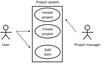
Use cases can also be described using figures. One of the most well known techniques for modelling use cases is the Unified Modelling Language (UML) use case diagrams which allows designers to graphically represent actors and their use cases.
Create project
User Project manager
Add item Project system
[image:22.595.216.387.403.506.2]review project
Figure 2.2: Use case diagram example (Windle and Abreo, 2003)
2.2
Requirements Engineering
This section explains how requirements can be captured. This is important for this study, because the main purpose of the situated Cognitive Engineering methodology is the process of capturing requirements.
2.2.1 Definition
Requirements engineering, or requirements capturing, is the process of acquiring require-ments. Many different definitions of requirements engineering exist in the literature. For this work the definition of software requirements engineering from Nuseibeh and East-erbrook (Nuseibeh and EastEast-erbrook, 2000) was chosen, because it matches the view of the situated Cognitive Engineering methodology. The definition is as follows:
“The primary measure of success of a software system is the degree to which it meets the purpose for which it was intended. Broadly speaking, software systems requirements
engineering (RE) is the process of discovering that purpose, by identifying stakeholders and their needs, and documenting these in a form that is amenable to analysis,
communication, and subsequent implementation” (Nuseibeh and Easterbrook, 2000).
The definition stated above describes RE as a process in which the purpose of the software system being considered is discovered. This purpose is the description of what the system should do, and why it should be build, hence theintention of the system.
2.2.2 Requirements Engineering Phases
Requirements engineering can be understood by considering the two main require-ments engineering phases, namelyrequirements development and requirements manage-ment (Wiegers, 2003). While the first phase is about defining requirements, the second phase is about managing the requirements, and their changes, during implementation. Although both phases share similar concepts and they often overlap in time, in this work they are treated as separate phases for simplicity. This study focuses only on the requirements development phase, because the key point of this study is capturing the requirements, instead of actually managing them. Therefore requirements management is out of scope of this study.
The requirements development phase consists of four sub-phases: (1)Elicitation, (2) Analysis, (3)Specification, and (4) Validation. Figure 2.3 shows the phases of require-ments engineering. The lower part shows the four sub-phases of requirerequire-ments develop-ment.
The order in which the requirements development phases are executed is of vital importance to understand and implement the business needs and wishes of the users.
Figure 2.3: Phases of requirements engineering (Wiegers, 2005)
TheAnalysisphase has the main goal of clarifying the results of the elicitation phase. The analysis sub-phase aims to derive more detailed requirements from higher-level requirements (Wiegers, 2005). This sub-phase also aims at creating prototypes, graphical analysis models and performing tests. Eventually, the analysis sub-phase provides better understanding of the information gathered during the elicitation sub-phase.
The Specification phase aims at capturing requirements information in such a way that it facilitates communication with various system stakeholders. Capturing require-ments information usually means documenting them in text docurequire-ments, although the use of graphical models and tables is advisable (Wiegers, 2005).
The Validation phase aims at ensuring the correctness of the captured requirements information, in such a way that these requirements satisfy the customer. In practice, the validation sub-phase implies the modification and rewriting of the earlier defined re-quirements. The requirements development process is an ongoing process, thus iteration between the four sub-phases is required in order to obtain proper requirements.
2.2.3 Requirements Engineering Methods
Several requirements engineering methods have been discussed in the literature. Tsumaki and Tamai give an overview of four requirement elicitation approaches (Tsumaki and Tamai, 2005).
1. Domain decomposition
2. Goal-oriented
The goal-oriented approach focuses on the goals that need to be achieved by a project, and translates them into requirements. For example, each use case could be translated into a requirement (e.g., KAOS Lapouchnian 2005).
3. Scenario-based
The scenario-based approach focuses on the creation of scenarios and their inte-grated set of use cases. This approach is the most relevant for this work, because the situated Cognitive Engineering method can be placed in that category. 4. Brainstorming
The brainstorming approach focuses on the creation of new products in areas where there is not much experience. It focuses on generating new ideas and creating an orderly system from chaos (e.g., KJ method Takeda et al. 1993).
Besides the requirements elicitation methods described above, one could use Agile development approaches, such as in (Beck et al., 2001). However, these approaches focus more on the software development process, which is out of scope for this work.
2.2.4 Requirements Engineering Tools
A requirements design specification can be represented as a textual document, however this has some limitations when projects become complex and interrelated requirements change often. Wiegers states the following four important difficulties (Wiegers, 1999):
Difficult to keep a textual document current, especially when requirements change rapidly.
Difficult to communicate changes to the affected team members. Difficult to store supplementary information about each requirement.
Difficult to define links between functional requirements and corresponding use cases, designs, code, tests, and project tasks.
Some tools have been developed specifically to address these problems. Wiegers states seven reasons why one should use a tool to manage requirements (Wiegers, 1999):
1. Manage versions and changes. Tools can track the changes which are made in the requirements specification. Keeping a history of changes makes it possible to revert to older versions.
3. Link requirements to other system artefacts. Defining links between re-quirements and other artefacts can help gain overview in the design specification. When a change is proposed, it is possible to trace the impact of the changes on other requirements.
4. Track Status. When using a tool it is possible to track the current status of the project. For each requirement status information can be added. This makes it possible to assert if the project is running on schedule.
5. View requirement subsets. Sorting, filtering and searching through the re-quirements baseline increases the insight in the rere-quirements specification.
6. Access control. Setting permissions for each user makes sure the right infor-mation is shared by the right people. Remote access makes cooperation with geographically separated group members possible.
7. Communicate with stakeholders. Communication among stakeholders is im-portant when developing a system. With the use of tools it is possible to keep the stakeholders up-to-date, which should reduce the risk of miscommunication.
Examples of popular requirements management tools are: Borland Caliber-RM (Bor-land Software Corporation, 2011), IBM’s DOORS (IBM, 2011a), IBM’s Rational Req-uisitePro (IBM, 2011b) and Sparx Systems Enterprise Architect (Sparx Systems, 2011).
2.2.5 Requirements Design Rationale
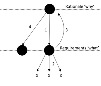
Requirements engineering answers the questions about ‘what’ the system should do. With software projects though, answering the ‘why’ question is evenly important because it opens the option to create alternative requirements when they become infeasible after verification. Answering the ‘why’ question is formally known as explicitly documenting the reasons behind decisions made when designing a system or artefact, hence stating the requirements design rationale. A design rationale should be, in its simplest form: explicitly listing the decisions made during the design process and the reasons why those decisions were made, as stated by Jarczyk (Jarczyk et al., 1992).
To create a suitable design rationale, a requirement should at least include the fol-lowing concepts: the reasons behind a design decision, its justification, alternatives con-sidered, the trade-offs evaluated, and the argumentation that led to the decision (Lee, 1997).
The important aspect of a design rationale is that it opens the option to create alternative requirements. Sometimes a requirement becomes infeasible after verification. The design rationale can then be used to trace the requirement back to its origin. This origin should contain the reason why the requirement was created, allowing alternative requirements to be defined.
X X X
1 3
4
Requirements ‘what’ Rationale ‘why’
[image:27.595.212.385.111.258.2]2
Figure 2.4: Using the design rationale to create alternative requirements
process more complicated. However, in the simplest case, the four steps in the process could be as follows:
1. A requirement is captured.
2. Verification shows that the implementation of the requirement is infeasible. 3. The designers trace the requirement back to its design rationale.
4. An alternative requirement is defined.
Chapter 3
The situated Cognitive
Engineering Methodology
This chapter describes the situated Cognitive Engineering (sCE) methodology. The purpose of this chapter is to get insight in the sCE methodology and its relation to other requirements engineering methods.
The outline of this chapter is as follows: Section 3.1 introduces the concept of cog-nitive systems engineering, Section 3.2 discusses the sCE methodology and Section 3.3 compares the sCE methodology with other requirement engineering methods.
3.1
Cognitive Systems Engineering
When machines are introduced, they are mainly created as an extension to the humans physical functions. They are designed to enhance the humans’ physical skills and to compensate for their limitations. Because the function of those machines are so closely related to the activities without them, not much effort normally goes into the design of the human interface.
However, with the capabilities of machines growing, more and more functionality comes into these machines making them systems that perform a process, so that the user moves away from the production floor to the control room. Instead of controlling a machine, the user has to control and/or monitor a process (Hollnagel and Woods, 1983). The machine no longer has simple actions and indicators, but becomes an information processing system that can perform complex activities and communicate in a seemingly intelligent way. Designing systems like these requires knowledge of the process of the mind, because humans have certain psychological limitations. This knowledge of the process of the mind is also known as human cognition.
The main idea of cognitive engineering is that a human-machine system needs to be seen as a cognitive system. A human and a machine working together can be seen as a single entity that interacts with an external environment. It is not merely a sum of its parts (human and machine), but a system that includes the psychological sides as well (Hollnagel and Woods, 1983). For example, if a machine does not consider the maximal workload of a user and it becomes too high, then the whole system may fail.
In 2005, an extended method of the cognitive engineering was proposed, namely the CE+ method. This method adds the technology as an input to achieve a better focus in the generation of ideas and the reciprocal effects of technology. Human factors are also made explicit and are integrated in the development process (van Maanen et al., 2005). In addition to the CE+ method, a method that is situated in the domain of interest was proposed by (Neerincx and Lindenberg, 2008), namely situated Cognitive Engineer-ing. This method uses the previously described assessments to establish a common design knowledge base, and to develop a kind of design guide for cognitive systems. (Neerincx and Lindenberg, 2008).
The area of Cognitive Engineering is a very large area of expertise, and incorporates many disciplines, like psychology, neuroscience, communication and many others. For this work, we mainly focus on the systems engineering area.
3.2
Situated Cognitive Engineering
This section introduces the situated cognitive engineering (sCE) methodology. First the basic principles of the methodology are given, then its four phases. Finally its main entities are described.
3.2.1 Basic principles
The situated cognitive engineering methodology is an extension to the CE+ method. The sCE methodology has been specifically designed to create cognitive systems that are situated in a domain.
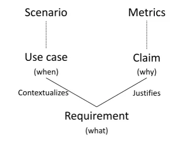
The sCE methodology can be used to create a sound requirements baseline for joint cognitive systems for research and development projects, which are often multi-party projects with distributed teams. Use cases and claims make sure the design rationale is described properly (Neerincx and Lindenberg, 2008).
Scenario
Metrics
Use case
Claim
Requirement
(what)(why) (when)
[image:30.595.210.382.103.243.2]Justifies Contextualizes
Figure 3.1: The relations between artefacts of the sCE methodology
3.2.2 sCE Phases
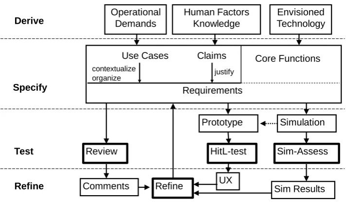
The sCE methodology consists of four phases, namely: derive,specify, test and refine. Figure 3.2 displays the elements in each of these phases, which are discussed below.
Derive
The derive phase is the starting point of the whole requirements design process. This phase has as input operational demands, human factors knowledge and the envisioned technology, which are all used to create the scenarios. These scenarios are used in the specify phase. Scenarios are stories about actors undertaking activities using technologies in a certain context. This phase can be compared to the elicitation phase as described in Section 2.2.2.
Specify
The specify phase is about capturing requirements from scenarios. The requirements
are created together with their design rationale (i.e., the use cases and claims). Each requirement should be justified by claims and each claim should be truthful and exclusive, otherwise they serve no purpose and should be removed. The core functions can be seen as modules that group requirements by certain functionality. For example, in a design project for an aeroplane, you could have a core function that defines the functionality for the autopilot. This phase can be seen as a combination of both the analysis and specification phase as described in Section 2.2.2.
Test
Prototype HitL-test
UX
Simulation Sim-Assess
Sim Results Operational
Demands
Human Factors Knowledge
Envisioned Technology
Derive
Refine Review
Comments
Test
Refine
Requirements
Use Cases Claims Core Functions
Specify
contextualize
[image:31.595.120.476.102.310.2]organize justify
Figure 3.2: The situated Cognitive Engineering process (UX = User Experience, HitL = Human in the Loop, Sim = Simulation) (Mioch et al., 2010)
results from the tests are evaluated and used to verify if the requirements meet the claims. If some requirements do not trigger the desired effect, then they should be refined and tested again. This phase, together with the refine phase, can be compared to thevalidation phase as described in Section 2.2.2.
Refine
The refine phase is executed after the test phase. The test results and comments from the test phase are processed to improve the requirements and claims in order to suit the needs of the stakeholders.
3.2.3 sCE Use Cases
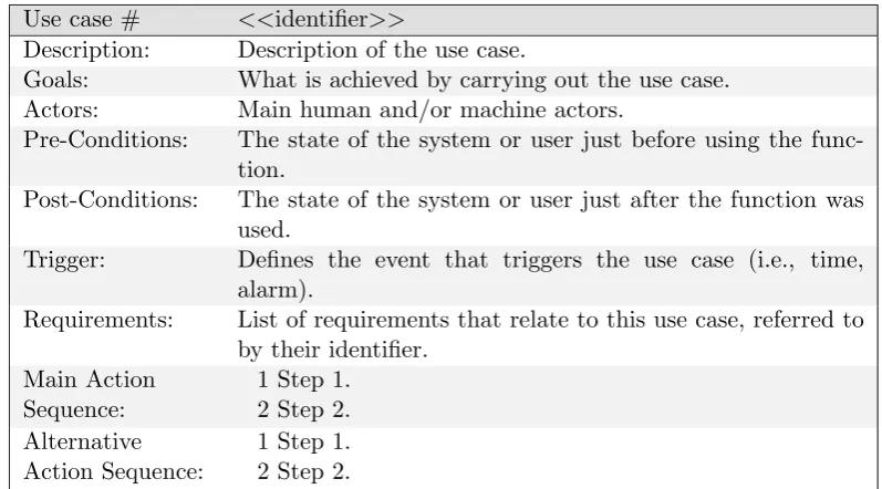
Use cases are one of the artefacts of the sCE methodology. Use cases are derived from the scenarios which are defined in the derive phase. A scenario can be seen as an instance of one or more use cases. Use cases should describe the general behaviour requirements and should have a specific specification format. Each use case should refer to one or more requirements.
Use case # <<identifier>>
Description: Description of the use case.
Goals: What is achieved by carrying out the use case.
Actors: Main human and/or machine actors.
Pre-Conditions: The state of the system or user just before using the func-tion.
Post-Conditions: The state of the system or user just after the function was used.
Trigger: Defines the event that triggers the use case (i.e., time, alarm).
Requirements: List of requirements that relate to this use case, referred to by their identifier.
Main Action Sequence:
1 Step 1. 2 Step 2. Alternative
Action Sequence:
[image:32.595.97.496.99.320.2]1 Step 1. 2 Step 2.
Table 3.1: Use case format
3.2.4 sCE Requirements and Claims
Requirements are artefacts that describe desired facts about the system. Each use case leads to one or more requirements. A requirement is justified by claims, which point out the usefulness of the requirement. Each claim has its positive and negative effect. If the negative effects outweigh the positive ones, then the requirement should be removed (Westera et al., 2010).
Claims play an important role in the sCE methodology. They are hypotheses that tell something about the goal the requirement needs to achieve. This goal is important because it points out why it is useful to implement a requirement. Because the sCE methodology focuses on the design phase, and not on the implementation phase, a lot of time can be saved if a requirement does not need to be implemented at all. The positive and negative effects, which are described in the claims, play a key role in deciding whether to keep a requirement because they determine the usefulness of the requirement.
Requirement # <<identifier>>
Description: Description
Claim Hypothesis (e.g., fast victim finding in areas that are inac-cessible for humans)
+ Upsides: (e.g., fast navigation time), [measures, such as time]
- Downsides: (e.g., no attention to areas the robot does not enter), [measures, such as number of misses]
Use Cases: List of use cases that link to this requirement, referred to by their identifier.
Table 3.2: Requirement format
3.3
sCE comparison
This section compares the requirements engineering process with the situated Cognitive Engineering methodology.
The sCE methodology focuses on the design of the requirements baseline, which can be compared to the requirements development phase of the requirements engineering phases. The methodology, however, does not treat the requirements management phase, as the sCE methodology only considers the design of the system, not the implementation. The sub-phases of the requirements development phase are similar to the phases of the sCE methodology. The elicitation sub-phase from the requirements development phase is similar to the derive phase from the sCE methodology. Both phases focus on discovering the needs of the stakeholders and defining the scope of the project.
Both the analysis and specification sub-phase from the requirements development phase can be compared to the specify phase from the sCE methodology. They focus on translating the needs of the stakeholders into requirements. Defining the design rationale is also important in these phases as it gives an answer to why the system needs to be built.
The validation sub-phase of the requirements development phase can be compared to the test and refine phase of the sCE methodology. In these phases the requirements baseline is tested to assess if the requirements meet the claims. If not, the requirements need to be refined or removed.
Several different types of requirements engineering methods exist. The sCE method-ology can be classified as a scenario-based approach because it focuses on requirements capturing using scenarios and use cases. This enables the requirements capturing process as a dynamic activity. Requirements are elicited from the domain of interest and can be identified by stakeholders. Because the activity is dynamic it encourages inspiration and imagination (Tsumaki and Tamai, 2005).
The positive effects should outweigh the negative effects, otherwise the requirement does not properly serve its purpose.
Together with the use cases, the claims define the design rationale of the system. By validating the claims one can make sure each requirement is useful. This makes the sCE methodology extremely suitable to apply when creating complex systems, because when the claims justify all the requirements, no unnecessary work is done when the system is implemented.
Chapter 4
The situated Cognitive
Engineering Tool (sCET)
We designed a tool called the situated Cognitive Engineering Tool (sCET) to support the process of creating project specifications using Cognitive Engineering. In this chapter we describe the design and prototype implementation of this tool.
Section 4.1 introduces sCET, Section 4.2 describes how the tool is designed, and Section 4.3 describes how the prototype is implemented.
4.1
sCET Motivation
Currently, in projects which apply the CE methodology, textual documents are used to capture the design specification. However, this has some limitations as stated by Wiegers (see Section 2.2.4). We designed a tool to provide a solution to these limitations.
Wiegers (1999) states four limitations of using textual documents. From these limita-tions, three main core functions have been derived, namelyCollaboration,Soundness and Completeness and Reusability, which are described in Section 1.1. These core functions currently cause the most problems when performing a CE project.
To address these limitations a tool needs to be used. Several Cognitive Engineering tools exists, but they do not focus on requirements development. Several requirements engineering tools exist as well, but these tools focus only on requirement development, and do not consider the human factor knowledge of the Cognitive Engineering method-ologies.
Because the current existing requirements engineering tools do not meet the require-ments for use with CE projects, a new tool had to be designed. In this tool the knowledge of requirements engineering and Cognitive Engineering can be combined, resulting in the Cognitive Engineering requirements tool.
4.2
sCET Design
To design the tool, we followed the sCE methodology. Since the sCE methodology consists of four phases, the same phases were followed, namely the derive, specify, test and refine phases. In this section the derive and specify phases are described. The test and refine phases are reported in Chapters 5 and 6, respectively.
4.2.1 Derive
In the derive phase, the operational demands, human factor knowledge and envisioned technology is tailored in a scenario. As an example project for designing sCET, the Mutual Empowerment project was chosen because it reflects a project in which people with different disciplines have to cooperate.
Scenario
TNO is a non-profit research organization which aims at developing and applying knowl-edge. Currently, TNO has about 3500 employees (TNO, 2010).
TNO is organized by a matrix structure in which projects are performed within themes. There are in total seven themes, namely:
Healthy Living Industrial Innovation
Defence, Safety and Security Energy
Transport and Mobility Built Environment Information Society
Besides these themes, TNO has three expertise centres. These centres house the scientists who perform projects. Each expertise centre consists of several expertise groups with a total of 67 groups. The expertise centres are:
Technical Sciences (36 expertise groups)
One of the projects within TNO is the Mutual Empowerment (ME) project. ME is a defence, safety and security project which aims at designing a mobile platform for soldiers in war situations. The goal is to create a system in which a soldier and some machine can work together to optimise the soldier’s performance in social patrols. Hence, mutual empowerment means that human and machine make each other more powerful. ME is a TNO-wide project, which means that multiple expertise groups are par-ticipating in this project. Each of these expertise groups specialized in a certain area of knowledge. Eleven groups participate on this project such as, for example,
Busi-ness Information Systems,Human Performance,Perceptual and Cognitive Systems and
Weapon Systems. These groups come from different expertise centres, differ significantly from each other and are often located in different cities.
All these groups are involved in the project because many aspects need to be taken in consideration when designing a complex cognitive system where human and machine have to work together. The system should not only be designed, but also the needs of the soldiers have to be taken into account. In the end the soldiers have to use the system and if the system does not conform to their needs they will most likely not use the system.
Because the members of the different groups have different disciplinary backgrounds, it is often difficult for them to cooperate. Different disciplines require a different way of thinking, and combining those is not an easy task. Furthermore, because TNO is located at multiple locations it is not always possible to meet in a single physical place when questions arise.
A way to improve communication so that project members know what each member is doing has become necessary. This should facilitate the alignment of the work of the groups so that working designs can be delivered in cooperation.
4.2.2 Specify
In the specify phase, the scenario is formalised into use cases, and requirements are derived from these use cases.
Use cases
Use case 1 UC 01
Description: Multiple users work on one requirement
Goals: Get better requirements
Actors: multiple users
Pre-Conditions: A sCET project is created by a user
Post-Conditions: The requirement is updated by another user.
Requirements: RQ 1
Main action se-quence:
1 User 1 creates a requirement 2 User 2 looks at the requirement
[image:38.595.107.491.386.600.2]3 User 2 makes changes to the requirement Table 4.1: UC 01
Requirements
Below, the requirements are given in the format described in Section 3.2.4. They are categorised by the three main core functions, namelycollaboration,soundness and com-pleteness and reusability.
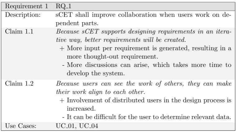
Collaboration. Collaboration is the key focus point of sCET. The goal is to improve the cooperation between people who work on a project and the stakeholders.
Requirement 1 RQ 1
Description: sCET shall improve collaboration when users work on de-pendent parts.
Claim 1.1 Because sCET supports designing requirements in an itera-tive way, better requirements will be created.
+ More input per requirement is generated, resulting in a more thought-out requirement.
- More discussions can arise, which takes more time to develop the system.
Claim 1.2 Because users can see the work of others, they can make their work align to each other.
+ Involvement of distributed users in the design process is increased.
- It can be difficult for the user to determine relevant data.
Use Cases: UC 01, UC 04
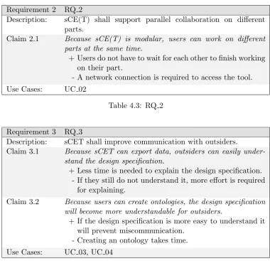
Requirement 2 RQ 2
Description: sCE(T) shall support parallel collaboration on different parts.
Claim 2.1 Because sCE(T) is modular, users can work on different parts at the same time.
+ Users do not have to wait for each other to finish working on their part.
- A network connection is required to access the tool.
[image:39.595.106.487.94.461.2]Use Cases: UC 02
Table 4.3: RQ 2
Requirement 3 RQ 3
Description: sCET shall improve communication with outsiders.
Claim 3.1 Because sCET can export data, outsiders can easily under-stand the design specification.
+ Less time is needed to explain the design specification. - If they still do not understand it, more effort is required
for explaining.
Claim 3.2 Because users can create ontologies, the design specification will become more understandable for outsiders.
+ If the design specification is more easy to understand it will prevent miscommunication.
- Creating an ontology takes time.
Use Cases: UC 03, UC 04
Soundness and completeness. The tool should make sure that the design speci-fication is sound and complete. This means that all the relevant data should be entered in a correct way. A sound and complete requirements baseline makes the design robust and understandable.
Requirement 4 RQ 4
Description: sCET shall enforce users to create an complete design spec-ification.
Claim 4.1 Because sCE(T) has defined its data fields, it discourages entering irrelevant data.
+ Less irrelevant data results in better understandable de-sign specifications.
- Sometimes additional information might be hard to en-ter.
Claim 4.2 Because sCE(T) has defined its data fields, it is possible to see what data is missing.
+ Missing data can be identified and added easily.
- If some fields are irrelevant for a specific case, they can-not be removed.
Use Cases: UC 05
Table 4.5: RQ 4
Requirement 5 RQ 5
Description: sCE(T) shall enforce the specification of a verifiable design specification.
Claim 5.1 Because claims are defined by metrics, claims can be tested on their validity.
+ If the claims are refuted, they can be refined to be re-placed by better claims.
- Defining adequate metrics takes time.
Use Cases: UC 06
Requirement 6 RQ 6
Description: sCET shall facilitate the learning of the sCE methodology. Claim 6.1 Because sCET is easy to learn the learning curve of the sCE
methodology is decreased.
+ New user can deliver results more quickly.
- Users could proceed in a disorganized way and not really learn the methodology.
- Users could dislike learning a new tool.
Use Cases: UC 07
Table 4.7: RQ 6
Reusability. The tool should make data reusable. Making the data reusable avoids situations of ‘inventing the wheel again’. It makes sure that important data is not lost and avoids making the same mistakes twice.
Requirement 7 RQ 7
Description: sCET shall make the iterative process insightful.
Claim 7.1 Because users can see the history of requirements better eval-uation choices will be made.
+ Users do not repeat previously made mistakes.
- Users can lose the overview because of too much infor-mation.
- Navigation across the design specification can become more difficult when more information is present.
Use Cases: UC 08
Table 4.8: RQ 7
Requirement 8 RQ 8
Description: sCET shall make design specifications reusable.
Claim 8.1 Because requirements from previous projects can be im-ported, new projects can start more quickly.
+ Importing old requirements results in less work for users. - Errors which were made previously can persist in related
projects.
Use Cases: UC 09
4.3
sCET Prototype
We built a prototype of the tool to tests its suitability. This tool was developed as a web-application with web-forms as graphical user interface. This prototype was deployed on a web server which was accessible through the Internet.
The tool has been built using PHP5 to create dynamic HTML pages with JavaScript which interact with a MySQL database. The interaction with the database was imple-mented using an Active Record library.
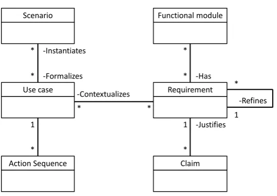
4.3.1 sCET Data Model
The data structure of sCET is displayed in Figure 4.1. This data model was derived from the schematic overview of the relations between the sCE artefacts as shown in Figure 3.1.
Project is the main object. sCET supports multiple projects simultaneously in the tool. The Project object makes sure that the data of each project is grouped together.
A project can have severalscenarios. Each scenario tells a story about the product being designed. A scenario can be formalised by specifying a use case. A use case describes the specific actions that can be taken in terms of action sequences. Action sequences give a step by step description of how the functionality is used. Each use case can have several action sequences.
From a use case, one or more requirements can be derived. A requirement describes specific information about what the system should be able to achieve. Claims give positive and negative effects of each requirement. Claims should justify the existence of each requirement.
As the specification process progresses, several requirements may be refined. Each requirement can be refined into multiple new requirements. The old requirement then becomes deprecated. Requirements can be grouped intofunctional modules. A functional module is a group of requirements with a some common characteristics, for example, a module with requirements for a user interface. They are the core functions of the product being designed.
4.3.2 Architecture
The tool is designed as an interface to the database scheme as shown in Figure 4.1. This data model was mapped onto several PHP pages, which interface directly with the database. A simple schematic overview of the pages is shown in Figure 4.2.
The figure shows that project.php is the centre part of the application. From that page it is possible to navigate to the artefacts of the design rationale.
The scenario, use case, module and requirement pages contain a list of the artefacts which are specified in the system and are connected through links. The use case and requirement pages also contain sequences and claims, respectively.
Action Sequence Use case Scenario * * 1 * -Instantiates -Formalizes Claim Requirement Functional module * * 1 * -Justifies -Has * * -Contextualizes -Refines * 1
Figure 4.1: sCET data model
data as shown in Table 3.2.
4.3.3 Interface
The interface was created usingHTML, to define the building blocks of the pages,CSS, to add visual style information and JavaScript, to make the interface dynamic. The interface elements are generated by the PHP pages.
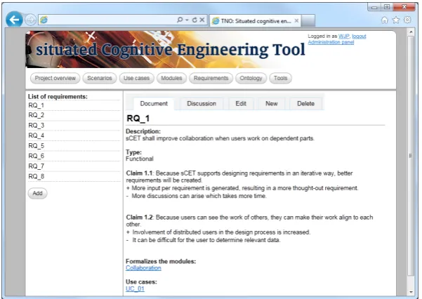
A screenshot of the current version of sCET is shown in Figure 4.3. This figure shows navigation buttons below the sCET logo. From each page the user can navigate to the project overview,scenarios,use cases,modules,requirements,ontology andtools pages.
The project overview screen shows general information about the particular selected project. It also lists news messages which can be added by the project manager. The Scenarios,Use cases,Modules andRequirements are the artefacts from the sCE method-ology. The Ontology screen shows the page where ontologies can be defined. In the current version, only a taxonomy is supported, which means that terms can be defined in a hierarchical way. Creating instances of terms and relations between terms, which would make it an ontology, is currently not supported. The Tools screen shows options for exporting sCET data to LATEX, XML or Microsoft Word’s DOC format.
In Figure 4.3 the requirement screen is selected. At the left side a list of requirements is shown. If the user clicks a requirement, the information of that requirement is shown in the central part of the screen. This information consists of the requirement attributes according to the format of the sCE methodology. At the top of the central part of the page there are tabs to navigate to the Document, Discussion, Edit, New and Delete screens. By default the Document screen is selected, as shown in the figure. The
claims requirement.php
module.php scenario.php
sequences usecase.php
project.php
Figure 4.2: sCET simplified page structure
a document by adding a reply. The Edit tab shows the page to change the information of the document, and is described below. TheNew tab can be selected to create a new document, and theDelete tab can be selected to delete the current document.
The Edit tab of a document shows the screen in which it is possible to change the information concerning this document. The input can be inserted through HTML forms. An example is shown in Figure 4.4, where a part of the edit screen of a requirement is shown. This figure also shows how the relations between artefacts can be selected. This is achieved by two boxes where the left box displays, for example, the available modules which can be selected by clicking the button with the ‘>’ arrow. The module then moves to the right box, which shows the selected related modules.
Figure 4.3: sCET requirement screen
[image:45.595.149.449.420.636.2]Chapter 5
sCET evaluation
This chapter describes how the sCET tool has been evaluated. This evaluation has been done to check the effectiveness of using our tool to support the sCE methodology. The claims described in Section 4.2.2 are verified by user experience.
Section 5.1 describes how the evaluation has been performed and Section 5.2 describes the results of the experiment.
5.1
Experiment Set-up
An experiment has been carried out to verify the effectiveness of sCET. This is done by deploying a first version of sCET on a server and organising a workshop where users have the opportunity to learn and use sCET.
Workshop
We organised a workshop to test sCET in two ways, namely with an informal and a formal evaluation. The formal evaluation consisted of a questionnaire and the infor-mal evaluation has been performed using the input from discussions. The group that attended the workshop consisted of members of the Mutual Empowerment project, as described in Section 1.1.
The course of the workshop was as follows: first the participants filled in the first part of a questionnaire about their expectations of using sCET. Second, the participants received a short oral introduction of the sCE methodology. Third, they went to a room where each participant got their own laptop on which they could work. They had one hour to define use cases, requirements and claims for their part of the project using sCET. If the participants had any questions they could ask the supervisors for help.
to share their thoughts on the workshop and the use of sCET in their project group. Finally, all participants filled in the second part of the questionnaire.
User Questionnaire
A user questionnaire has been filled in by the participants to verify the user experience with the usage of sCET. The questionnaire was split into two parts, namely a part that is filled in at the beginning, and a part that is filled in at the end of the workshop.
The part that is filled in at the beginning of the workshop consists of two parts, namely questions about general information about the participant, like gender and age, among others, and questions focusing on the expectations of using sCET. This second part consists of eight multiple-choice questions and two open questions where partici-pants can put down any other thoughts before starting with sCET.
The part that filled in at the end of the workshop consisted of seven parts, as de-scribed below:
1. The situated Cognitive Engineering Methodology. This section focuses on questions about the sCE methodology, whether the participants like it and think if it is useful for their work.
2. sCET collaboration. This section focused on questions about whether the partici-pants think sCET helps improve cooperation between project members.
3. sCET soundness and completeness. This section focused on questions about whether the users think sCET will helps them achieve a sound and complete design speci-fication.
4. sCET reusability. This section focused on questions about whether the user expects that sCET data can be reused in other projects.
5. sCET (with sCE experience). This section needs to be filled in by users who have sCE experience. It focused on questions about whether the users think that using sCET is better than textual documents.
6. sCET (without sCE experience). This section needs to be filled in by users without sCE experience. This focused on questions about the experience the users had learning sCET.
7. General remarks. This section focused on open questions where participants can put down any other thoughts they have about using sCET.
Logging
The activity on the usage of sCET was logged using Google Analytics. This application keeps track of how the users navigate in the tool. A few features that are supported are visitors count,page view count andaverage time on site(Google, 2011). The information from the logging was used to improve the usability of the tool.
Besides the use of Google Analytics, logging information was stored in a local database. This was done to get additional information on areas which are not supported by Google Analytics, such as which data was entered by the users of the tool.
To fully take advantage of the logging features, a lot of usage of the tool and in-formation about this usage is necessary. Because of the small user-base, the results of the logging features are not addressed in this thesis. However, the features have already been implemented so that they can be used directly when the usage increases.
5.2
Experiment Results
This section presents the results of the evaluation of sCET. Two types of evaluation were done, namely an informal and formal evaluation.
5.2.1 Informal Evaluation
During the workshop we obtained a lot of responses with practical tips on how the tool should be improved. Besides these practical tips, some ideas were also given on the general idea of using sCET.
Guidance. The participants mentioned that they required quite some guidance on the definition of use cases and requirements. Some participants had little or no experience with the sCE methodology, which made it hard to figure out how to write down the information. The level of depth in which they had to create requirements was also difficult to figure out.
Reporting. The participants had many questions about the reporting capabilities of sCET. They found it very important to be able to export the data to other programs, to further use it when creating reports. Although all information is accessible through sCET, it remains important to be able to collect all data in a central document which can be adjusted and printed out.
Usability. Participants gave a huge importance to usability, in the sense that the program should not have any quirks which could result in users getting irritated. For example, if users press the wrong button, data should not be lost.
Security. There were some concerns about the security of sCET. TNO is often
Visual design. The visual design of the program is important because bad design dis-encourages new users from using it. The design should be in such a way that data is shown in a clear and evident way.
An interesting side result from the workshop came from a project member who joined the project after it was started. For other members it was not really apparent what this new member was going to do. At the workshop, he entered some simple requirements with just a few lines of information. At the presentations of the results he presented his work. Although he was not certain of his own work, other people started to understand what he wanted to do in the project. With those few lines he could communicate with the other project members by showing what he was doing. Hence, he brought the project members to the same level of thinking as himself.
5.2.2 Formal Evaluation
The questionnaire was filled in by five participants. These participants came from dif-ferent disciplines and work on difdif-ferent parts of the ME project.
We statistically evaluated the results from the questionnaires with descriptive statis-tics. The central tendency and dispersion of the data is calculated and shown in Ap-pendix D.
Three values are calculated, namely mean, median and range. For each claim, the results are evaluated. Some claims are difficult to verify, because it requires sCET to be used for a longer period. Therefore, they have not been included in the evaluation.
Since the questionnaire was only filled in by five participants, and no control group was used, no statistical significance over the mean values can be measured. Therefore it is also important to look at the median and range values, which tell something about how the participants agreed with each other. These values, in addition to the informal evaluation can still say something about the user experience if all participants agreed with each other. Below the results of the questionnaire are shown. They are grouped by the three core functions, namely Collaboration, Soundness and Completeness, and Reusability.
Collaboration
Claim 1.2 Because users can see the work of others, they can make their work alig