Advanced Manufacturing: Polymer & Composites Science
ISSN: 2055-0340 (Print) 2055-0359 (Online) Journal homepage: http://www.tandfonline.com/loi/yadm20
Hand layup: understanding the manual process
M. Elkington, D. Bloom, C. Ward, A. Chatzimichali & K. Potter
To cite this article: M. Elkington, D. Bloom, C. Ward, A. Chatzimichali & K. Potter (2015) Hand
layup: understanding the manual process, Advanced Manufacturing: Polymer & Composites
Science, 1:3, 138-151, DOI: 10.1080/20550340.2015.1114801
To link to this article: https://doi.org/10.1080/20550340.2015.1114801
© 2015 The Author(s). Published by Taylor & Francis
Published online: 12 Nov 2015.
Submit your article to this journal
Article views: 8853
Hand layup: understanding the manual
process
M. Elkington*, D. Bloom, C. Ward, A. Chatzimichali and K. Potter
ACCIS, Queens Building, University Walk, UOB, Bristol, BS8 1TR, UK
Abstract The hand layup of pre-impregnated woven
materials is still a large part of the composite manufacturing industry, requiring the skills and experience of a human workforce to form flat plies into complex shapes. It is capable of producing high performance and complex parts, but can be an expensive and variable process. Despite its importance, there appears to have been very little research into the actual methods and techniques used by workers to manipulate flat sheets of composite material into shape during layup. This work presents the first known detailed study of the approach and techniques used by laminators. Four participants laid up onto 15 different shaped molds that replicated features commonly found on composite components. The actions used in layup were grouped into eight distinct techniques. Use of these techniques across tasks of different geometry, ramp angles, radii and drape path was identified using
video analysis techniques from the ergonomics field. This revealed strong links between specific features and techniques, revealing a systematic approach to layup. This has enabled the first step toward producing a design for manufacture knowledge base surrounding hand layup. This could then be used to inform the development of the layup process, improve training methods and assist in the design of future automated solutions.
KeywordsHand layup, Drape, Ergonomics, Observation, Technique
Cite this articleM. Elkington, D. Bloom C. Ward A. Chatzimichali K. Potter.Adv. Manuf.: Polym. Compos. Sci., 2015, 1, 128-141
Introduction
Advanced composite materials can offer a range of advan-tages, which have made them desirable in many high performance applications. Consequently, composites are not only seeing an increased use in applications from racing cars, aeroplane components, and sporting goods but also lower cost higher volume industries such as automotive.1,2 With this broadened use has come an ever increasing demand on the manufacturing processes to continue high standards of quality but now combine higher volumes and lower costs.
High-performance composites consist of a matrix material reinforced by layers of alignedfibers. It is thesefibers that give composites excellent structural properties, but also make them inherently complex to manufacture as they must be built up layer by layer. The manufacturing process
known as `hand layup' involves manually laying down indi-vidual layers or `plies' of a form of reinforcement known as `prepreg'. This consists of thousands of fibers, which are pre-impregnated with resin and bundled into tows and arranged either in a single unidirectional ply or woven together. The layup process involves manipulating each ply into shape by hand and then firmly stuck to the previous layer or mold surface leaving no air pocket between plies.
This can produce high-quality complex features, has relatively low start-up costs, and is highly adaptable to new parts and design changes. However, it is far from perfect, as production rates can be low and the costs of both materials and labor are sometimes high. As with other manual pro-cesses, there is also potential for discrepancies between parts caused by human variation.3 Despite these dis-advantages, the adaptability and quality provided by hand layup means it remains a key part of the composite industry, providing the main manufacturing method for many
*Corresponding author, email [email protected]
Original Research Paper
© 2015 The Author(s) . Published by Taylor & Francis
manufacturing facilities.4–6It is then perhaps surprising that there is little documented knowledge about how the manual portion of the hand layup process is carried out. A review of leading textbooks gives very little information, with most authors condensing their description of the actual layup process into a single sentence.7–11Recent research appears to have been more focused on refining newer automated techniques such as automated fiber placement (AFP)12 rather than on further studies of hand layup such as the one presented here.
One highly cited industrial ergonomics study13states how crucially important it is to understand a manual process before attempts should be made to improve or alter it. This is seconded by a seminal paper by Bainbridge, who stresses it is crucially important to understand the skills and thought process of a worker, even within an automated environ-ment.14This approach has been put into practice, where the mechanics and actions of human hands were successfully used to inspire the design of gripping robots.15During the design of previous automated systems to pick, place, and consolidate large sheets of prepreg, the skills and capabilities of laminators were explicitly noted, but there was no evidence of direct observations of laminators at work.16 Similarly, an automated system that deals with sheet prepreg claimed to capture `the mechanics of draping' but fails to directly reference any real layup examples.17Another study also failed to explore any existing hand layup techniques while developing a new end effector based on compressed air.18 If some of the disadvantages of hand layup are to be tackled, a fuller understanding of the process is a necessary precursor. One example of this kind of study within the composites industry was the observation of workers rolling resin into dry reinforcement material by the Kyoto Institute of Technology.19
Material deformation
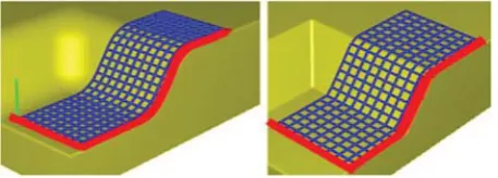
While the manual process appears to have been left largely untouched, the way the material deforms is well understood. It is established in analytical shell theory that a flat sheet cannot be translated to a double curved surface or vice versa, without some in-plane deformation.20This is demon-strated in Fig. 1 using an inextensible sheet draped over surfaces with double curvature. Figure 1ashows a `material deficit', where in order to place the inextensible sheet onto the mold, slits or `darts' are required at the edge of the material to makeup for the deficit in material. Figure 1b
shows a `material excess', where in order to place the inex-tensible sheet onto a mold, folds are now required at the edge of the ply because of the excess material. Creating folds or cuts in carbon fiber reinforcement causes major structural weaknesses,21although it is not uncommon to see darts being created in layup on the shopfloor where they are absolutely needed because of reaching the limit of prepreg deformability.22
Carbon fiber tows themselves are inextensible in the hands of a human being, but the woven structure of the reinforcement has alternative deformation mechanisms. The most dominant of these is in-plane `trellis' shear, where the individual tows can rotate and slide past each other.3 Unlike isotropic materials, this deformation only allows the structure to elongate in the directions eitherþ458or2458 to the tows, while simultaneously contracting perpendicu-larly. As a result, specific patterns of shear deformation need to be created for each mold and fiber orientation. For complex molds, this is often non-intuitive, and simulation programs, such as virtual fabric placement (VFP), have been developed to predict the required pattern.3 As far as the authors are aware, VFP is unique in that it allows the user to totally dictate where the ply is first stuck down, and then uses a kinematic model to calculate how the resulting shear would subsequently develop. It was used to show that even for the same mold shapes with the same nominal fiber orientation, multiple different shear deformations can be achieved depending on the starting points. Further work showed these specific, sometimes non-intuitive starting points have a significant impact on the time taken for layup.23,24
Studies at Bristol University have looked into other aspects of layup. Virtual fabric placement outputs were combined with expert knowledge to create a guidance system based around projectors rather than lasers, which gave the ply outline, basic shear information and uniquely the order in which a ply layup should be tackled.25In the other work, the methods for sticking and sticking the prepreg layers onto the mold, and the use of `Dibber' tools, were investigated.26 Through an analysis of the actions, a new multipurpose tool was designed to enable laminators to form many shapes with a single tool. Current examples of improvements to the layup that have been readily adopted are automated ply cutting, and laser guidance systems, which aim to save time and reduce variation by providing outlines to show operators exactly where a ply needs to be placed.27
[image:3.595.66.293.620.694.2]The key knowledge gap clearly lies in understanding how the laminators physically manipulate the reinforcement into the shapes predicted by VFP and other simulation packages. The work presented here is targeted at bridging this gap by examining the layup process on a step by step level to understand the physical process the laminators are carrying out. The aim was to have establish a list of techniques used by the laminators, and to understand how, where and why they are used, and eventually what aspects of layup make effect the particularly of different molds. The core process has changed little in 30 years, so there is very likely to be some scope for improvements, which could bring it up to date and offer real-time savings, and the long-term applications of this new understanding are expected to be threefold
Figure 1 A demonstration of how forming an inextensible sheet into a shape of Negative Gaussian curvature a
Improving the current process
If the designers and engineers have a better understanding of layup, they may be able to design parts are that are easier to make, potentially resulting in higher production rates, reduced variability and lower costs.
Improve training and communication
A detailed understanding of the techniques used during layup will make it possible to explain `how' to achieve specific deformations in a reinforcement. This has the po-tential to make it easier to train and instruct new laminators, as well as beginning to develop more comprehensive instruction sets to establish a greater level of repeatability and reliability between operators.
Lay the foundations for automation
By understanding how human beings achieve deformations in a prepreg sheet, it will provide the designers with a much better starting point to design new automated processes to tackle some of the short comings of current systems.
Experimental method
To begin understanding how reinforcement is manipulated into shape, an experiment was set up to allow examples of the process to be observed in detail. A series of layup tasks were developed to recreate 15 typical mold features, cov-ering convex and concave corners, saddle shapes, male and female molds, as well as tight and open radii, a variety of ramp and shear angles, and different layup approaches. Rather than have a single complex part, the features were kept separate to enable side by side comparisons. The mold
geometry, starting point and subsequent details of each task are summarized in Table 1 below, and are outlined in more detail in Results section.
Four participants worked through all 15 tasks sequentially three times, in the order shown in the second column of Table 1, which is slightly different to the task numbers used in this paper here. They were arranged approximately in order of difficulty, starting with small plies with no shear, moving to medium sized plies in order of increasing shear angle and onto larger plies. There would have naturally been some learning curve effects as they completed each task three times and worked through the range of increasingly difficult tasks, and the analysis here represents only thefinal attempt at each ply. An analysis of these learning effects is beyond the scope of this paper, but will be the subject of further work by the author. Two participants were pro-fessionals with 20 years or more experience in a variety of motorsport and aerospace companies, while the others had moderate experience of layup up with woven prepreg. All participants will remain anonymous. Each task was pre-sented to the participants with a full VFP diagram such as those seen in Fig. 2, highlighting the starting points, con-straints and to illustrate any required shear deformation. The molds were fixed onto a table top, approximately 200 mm from the edge, in the orientations shown in Results section, such that with the exception of Tasks 1 and 2, the tasks were all symmetrical to the left or right. After each attempt, the participants were given feedback on the quality of the layup, focusing on meeting datums and avoiding wrinkling and bridging. Every layup attempt wasfilmed using a HD camera positioned 500 mm vertically above the mold to allow the footage to be revisited for analysis. All tests were conducted
Table 1 List of layup tasks
Task No. Order of completion Figure Description Ramp angle Ply size/mm
1 1 Figure 2 Two flat sections linked by a
ramp angle. Task 1 has a large corner radius.
608 70£200
2 2 608 70£200
3 3 Figure 5 A negative Gaussian curvature
shape, where the layup begins in a tight v-shaped recess.
308 140£140
4 5 608
5 4 Figure 9 An external 3 sided corner,
forming a positive Gaussian curvature shape,
308 140£140
6 6 608
7 7 Figure 11 A large flat surface with a recessed corner region, linked by ramps at variable angles, layup starts in the recessed region.
308 230£230
8 10 458
9 13 608
10 8 Figure 14 A large flat surface with a recessed corner region, linked by ramps at variable angles, layup starts on the upper flat region.
308 230£230
11 11 458
12 14 608
13 9 Figure 16 A large flat surface with an elevated corner region, linked by ramps at variable angles, layup starts on the lower flat section
308 230£230
14 12 458
in clean room conditions, using 2£2 Twill (Carbon fiber) MTM49.28 The professionals were allowed to use their own personal tools or `dibbers' to assist in layup if they required. The methods used in this test were approved by the University of Bristol research Ethics administrator.
Analysis methods
The aim of this study was to understand what the laminators were physically doing to the prepreg in order to achieve the required shapes. Layup is a difficult process to observe because both the actions made by the participants and the effects on the prepreg need to be observed and recorded in parallel. Initial observations of the layup video footage revealed at least 23 different orientations of the hand in use. The location and time of every contact with the prepreg made by the laminator was recorded. This provided a huge amount of data, which was difficult to draw any conclusions or understanding from. Alternative approaches such as the direct video movement capture techniques used by the Kyoto Institute of Technology were considered, but they were reliant on the operators using a roller as the sole end effector.19 Prepreg layup uses such a variety of hand configurations and tools that this technique was not appli-cable. An alternative technique was developed, based on the ergonomic studies of Pouydebat et al.29 and Kuniyoshi
et al.30Instead of looking at the details of individual contact points, a higher level approach was taken where actions were grouped in broader `techniques'. Initial observations showed that grasps and the application of in-plane pressure were used in often repeated combinations. The combi-nations will be referred to as `techniques' from herein.
The analysis focused on observing every contact with the prepreg made by the laminators. `Contacts' which were only deemed to be interacting with the prepreg in order to stick it down onto the mold were not recorded as part of this study as they have been covered previously by Jones.26All other actions were categorized into a range of techniques. Initially, there were five techniques, but as new actions were observed, which were significantly different to the already categorized techniques, extra techniques were added. Eight distinct techniques were eventually identified, each of which will be explained in detail in Results section. The analysis focused on capturing the purpose of each technique, and a record was made in a tally chart every time a technique was used on each individual layup attempt, allowing the different tasks to be compared. The analysis was carried out by a single observer, and a second observer repeated the analysis
for a selection of example layups and the total for each task was within an average of 10%.
Results
The presentation of the techniques and their specific uses are split into three sections. First, a brief description of the eight techniques is given in Techniques section. Then, in Tasks 1–2: basic lamination section, each task will be presented in more detail, in the order of increasing complexity, along with the layup observation results and an introduction to the techniques that were most frequently observed in use during layup. Finally, in Discussion section, the reasons why there are so many different techniques and differences between them are discussed. This is followed in Discussion section by a more detailed analysis discussing the application methods, purpose, and limitations of each technique.
Techniques
One handed guidingOne hand holds the prepreg securely onto the mold surface while the other hand is used to grasp the ply and move it in order to align it with a datum on the mold surface, as can be seen in Fig. 3. Once aligned, the grasping hand generally lowered the prepreg onto the mold surface and then both hands were used to stick it down.
Two handed guiding
Both hands grasp the ply in order to position the ply on the mold. Often one or both hands then stick the prepreg to the surface once it is aligned. This can also be used to `shape' the ply tofit in or around a mold, as can be seen in Fig. 6.
Manual folding
One or both hands are used to manipulate the prepreg out of plane in order to create organized and manageable folds in the prepreg, often to deal with a material excess in the prepreg, as seen in Fig. 12.
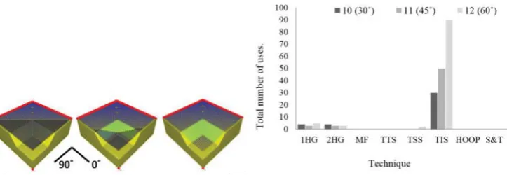
Hoop shearing
Fingers, thumbs or other molds are arranged into a single curved front, which is slowly moved across a region of pre-preg, sticking it to the mold while also creating a `hoop' stress in the folded region of the material, which in turn creates shear, as shown in Fig. 8.
Double-tension shearing
Both hands grasp the reinforcement at two separate locations, which are along a line^458to thefiber directions and apply tension in opposing directions to create shear, as shown in Fig. 7.
Tension-secured shearing
[image:5.595.66.295.52.134.2]One hand grasps the prepreg and applies tension in order to create shear, while the other hand secures the prepreg to the mold surface in order to prevent slippage, as seen in Fig. 10. Once shear is created, the ply is either released or lowered onto the mold surface to be stuck down.
Tension and sticking
The same as tension-secured shearing but the securing hand slides along the ply, sticking down the prepreg at the same time as shearing, as seen in Fig. 13.
Mold interaction shearing
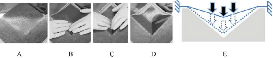
[image:6.595.111.482.54.165.2]The ply is pushed into a recessed region of the mold, which creates sufficient tension in the ply to create the required shear deformation, as seen in Fig. 15.
[image:6.595.115.479.201.302.2]Figure 3 (Left) ‘One-handed guiding’ in use during task 1. (Right) Schematic force diagram of technique (not to scale)
Figure 4 Corner consolidation methods (Top) participant using finger nails to get prepreg into the corner, (Bottom) participant using dibber tool (not to scale)
Figure 5 (Left) Schematic of Task 4. Task 4 is the same shape but with a steeper 608ramp section. (Right) Graph showing total technique usage for Tasks 3 and 4 (red line: starting point; blue: no shear deformation; green: shear deformation) (not to scale)
[image:6.595.111.481.354.524.2] [image:6.595.113.477.583.657.2]Layup observation results
Tasks 1 – 2: basic laminationThe first two tasks did not require any shear and are a benchmark to identify the techniques simply used to handle, move, and align prepreg, as well as those for working around internal corners. Both tasks start on aflat area and then progress up and over a 608ramp as shown in Fig. 2. A datum (shown in red) runs along two sides, and there is no required shear deformation. Both corners on Task 1 have a 30 mm open radius, while Task 2 has a tighter 3 mm radius. Thefirst techniques used
[image:7.595.118.496.52.124.2] [image:7.595.117.486.159.240.2]in layup, which was consistently used by all the participants was to initially align the prepreg, was `one-handed guiding'. For both tasks, all layup attempts then progressed onto sticking down the entire lowerflat section of the ply before proceeding up on to the ramp section. This consolidation was done using the pads of the thumb andfingers, or using a hard plastic tool, often referred to as a `dibber', as shown in Fig. 4. The key difference between task 1 and 2 is how the corners were stuck down. The 30 mm radius of the corners in Task 1 is similar in size to that of a humanfinger; therefore, it was always consolidated Figure 7 (Left) Double-tension shearing used during Task 5. (Right) Schematic force diagram of technique (not to scale)
Figure 8 A, B Two examples of Hoop shearing using either fingers or thumbs to form a single front,Cschematic of the Hoop shearing technique from side view,Dschematic of the Hoop shearing technique from top view (not to scale)
Figure 9 (Left) Schematic of Task 6. Task 5 is the same but with shallower 308ramps (not to scale). (Right) Graph showing total technique usage during Tasks 5 and 6 (red line: starting point; blue: no shear deformation; green: shear deformation) (not to scale)
[image:7.595.114.488.289.428.2] [image:7.595.119.485.486.574.2]Figure 11 ACAD image of the tooling for Tasks 7 – 12. Task 13 – 15 feature an inverse of the ramp section, creating a ‘male’ tool,BGraph showing total technique usage during Tasks 7 – 9,Cvirtual fabric placement (VFP) diagram of layup for Tasks 10 – 12 (red line: starting point; blue: no shear deformation; green: shear deformation) (not to scale)
Figure 12 Example of folding material to accommodate the shear during task 8 (not to scale)
Figure 13 ‘Tension and sticking’. (A) Prepreg requiring shear, (B) tension applied, (C) Prepreg smoothed while under tension, (D) sheared prepreg, and (E) schematic force diagram of technique (not to scale)
[image:8.595.111.481.468.568.2] [image:8.595.116.478.617.742.2]by hand using the pad or tip of thefinger. The tighter radius on Task 2 meant the pad or tip of thefinger was no longer effective, requiring the laminators to usefinger nails or dibbers to press the prepreg into the corner (see Fig. 4). Further analysis of these tools and other sticking methods can be found in Ref. 27.
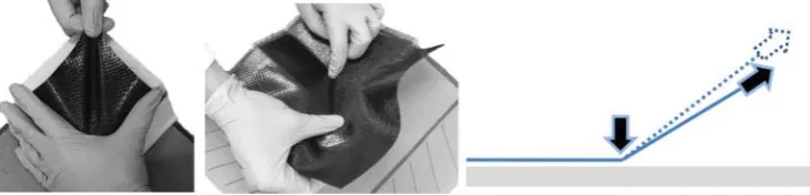
Tasks 3 – 4: shearing reinforcement over a Negative Gaussian curvature (‘saddle’) mold
Tasks 3 and 4 required participants to drape a 140£140 mm ply over a mold surface with negative Gaussian curvature, forming a `saddle' shape. As illustrated in Fig. 5, participants were instructed to begin with the ply in a recessed `v-shaped' region then progress over a saddle-shaped section up on toflat region on top of the mold. Figure 1 showed how these plies would need a slit or dart cut in them to form this shape if they were an inextensible material because there is a material `de-ficiency' toward the edge of the ply. However, participants were forbidden to make any slits in the material. Instead, the woven prepreg had to be sheared to compensate for the material deficit. Both tasks share the same basic geometry but differ in that they feature ramp angles of 308and 608, respectively.
The techniques used in Tasks 3–4 are shown in Fig. 5. To begin the layup, the one-handed guiding technique was generally used for initial placement of the plies, much like Tasks 1–2. In addition, some laminators used two-handed guiding to both position and shape plies. The required shear angle in Task 3 is so low that the participants generally did not use any special techniques to form the shear. However, on Task 4, the much higher shear deformation meant the participants sometimes used the `double-tension shearing' technique. This was only used four times in total, and most operators used a hybrid of sticking and tension generation, which is classified here as the `Hoop shearing' technique. There was a single recorded use of another technique known as `tension-secured shearing', which is covered in Tasks 5–6: shearing reinforcement over a convex curvature mold section.
Tasks 5 – 6: shearing reinforcement over a convex curvature mold
Tasks 5 and 6 also featured shear, but presented a different challenge to Tasks 3 and 4 because of the shape of the mold. The ply was formed over a doubly curved convex surface, as illustrated in Fig. 9, where Task 5 has a 308ramp and Task 6 a 608 ramp. The initial positioning of the ply was almost exclusively completed using one-handed guiding. Generally, one of the sloped faces was consolidated in its entirety, before moving onto the other and then up onto the top surface. For tasks 5 and
6, the shear is consigned to a single region on the top surface, with approximate shear angles of 58and 258for Tasks 5 and 6, respectively. The shear angle on Task 5 was so small that sticking alone was generally sufficient to create the required shear, but there was some limited use of tension-secured shearing, which is shown in Fig. 10. For Task 6, the higher shear resulted in it being used nearly three times as frequently as Task 5.
Tasks 7 – 9: complex parts 1 – working ‘up’ the recess
The remaining Tasks 7–15 all created the same shape, which was both larger and more complex than the previous tasks. Every task featured a 230£230 mm ply with a nominal 08–908 orientation, but there were a number of crucial differences. A diagram of the mold is shown in Fig. 11, featuring aflat top surface and a recessed corner with ramps of variable angleblinking the two. The tasks are divided into three sets, each containing versions of the same layup with ramps at 308, 458 and 608. The ramp length remains the same; hence, the recess is deeper on the steeper ramped mold. Tasks 7–9 and 10–12 differ in required deformation pattern, caused by starting at the front or back of the mold, respectively. For tasks 13–15, the mold recess is inversed to form a male mold, but the finished part shape and defor-mation pattern is the same as Tasks 10–12.
Figure 11 also shows the VFP pattern for thefirst set of tasks on this mold. Tasks 7–9 began by aligning the ply to a datum on the near side of the mold including the recessed area. As with previous tasks, this was achieved using one-handed guiding once the ply had been initially positioned on the mold. Figure 11 also shows how the steeper the mold became, the more one-handed guiding was used, with Tasks 7–9 requiring 13, 27 and 29 uses, respectively. As layup progressed onto the concave region, the excess material formed folds in the ply (similar to those seen in Fig. 1) and participants sometimes manipulated the ply out of plane to control them and prevent unwanted prepreg self-contact, which can be difficult to undo. This was often carried out with a one hand, while the other was used to stick the reinforcement to the mold. Examples of this `manual folding' can be seen in Fig. 12. Task 7 only has minimal curvature because of its shallow ramps and so only three instances of manual folding were recorded, and the steeper Tasks 8 and 9 saw increasing instances of manual folding. In order to permanently remove the excess material from the prepreg, shear deformation needed to be created in the plies.
[image:9.595.69.538.56.156.2]Throughout all three tasks, the most popular technique was `tension-secured shearing', where one hand secured prepreg to
mold surface while the other applies in-plane tension, as seen in Fig. 10 previously. Similar to the manual folding technique, Fig. 11 shows that the usage of tension-secured shearing increased for the steeper ramped molds. In some instances, tension-secured shearing was used to shear small areas of material just before they were consolidated. Alternatively, it was sometimes used to shear larger areas of prepreg further in advance of consolidating the prepreg. By shearing larger areas, participants were able to approximately create the out-of-plane deformation, allowing the prepreg to conform onto the mold shape, helping to reduce folding and make aligning the datum's easier. When shearing the corner section (the middle of the three stages of layup shown in Fig. 11), the tension direction was not in the plane of already consolidated region. Thus, the securing force in tension-secured shearing also prevented the ply directly peeling of the surfaces, as well as preventing slippage. The operators made use of `tension and sticking', which combined the direct tension application of `tension-secured shearing' with a sticking action. Seen in Fig. 13, this is a subtle yet important difference, as the shear is being created simultaneously to the ply being stuck to the mold.
Tasks 10 – 12: complex parts – working ‘down’ the recess
Figure 14 shows how these tasks started at the rear of the mold (rather than the front as in Tasks 7–9), so the layup progressed `down' the recess ramp, creating a very different shear deformation pattern to Tasks 7–9. The initial ply placement was achieved with a familiar mix of two-handed guiding and one-handed guiding to align the ply. Unlike Tasks 7–9, the use of these techniques did not increase significantly with the steepness of the mold. For these tasks, the sheared region is down inside the recess rather than on theflat region, and the difference in location is mirrored by a difference in the techniques used. There were no recorded uses of tension-secured shearing, which had been the key technique for the previous three tasks (see Tasks 7–9: complex parts 1 –working `up' the recess section). Instead the operators used `mold interaction shearing', which is shown in Fig. 15. This did not involve any grasps, and simply involved pushing the prepreg into the recess to create in-plane tension in the prepreg, and its use is explained further in Shearing a material deficit section.
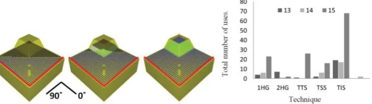
Tasks 13-15: complex parts – inverse ‘male’ mold
Studying Fig. 16, it can be seen that the ply shape and defor-mation pattern for Tasks 13–15 are identical to 10–12, but with
an inversed `male' mold shape. This detail had a significant effect on the layup process. As with all the previous tasks, one-handed guiding and two-one-handed guiding were in use for the initial ply aligning. Much like Tasks 7–9 the use of one-handed guiding in particular increased as the ramp steepened, 4, 6 and 23 uses were recorded for Tasks 13–15, respectively. While the previous six tasks tended to favor the use of a single particular shearing technique, the inverse mold shape required a mix of `tension-secured shearing', `double-tension shearing' and
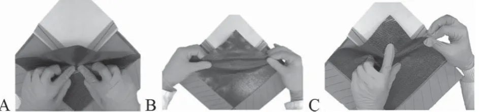
`Mold interaction shearing', and an example of each being used are shown in Fig. 17. The reasons for this diversification are explored along with the reasons for the use each technique in Discussion section.
Discussion
There appeared to be a general bias toward using specific techniques on certain tasks, suggesting each technique has its own unique purpose, requirements for use, and limitations. The eight techniques are discussed at length here, in the context of ply handling, organization, shearing a `material excess' and shearing a `material deficit'. Their respective characteristics are summarized in Table 2.
Ply handling
One-handed guiding and two-handed guiding techniques are associated with picking up, locating, aligning and, if necessary, shaping the ply. Both can be used to pick up and move a ply, but two handed guiding was not used during Tasks 1 and 2, potentially because the plies are small enough to hold with just one hand and maintain their shape. For aligning purposes, both techniques were used on all tasks from 3 onward as the ply size increased. Once any part of the ply had been stuck to the mold, one-handed guiding was the only option available and is extensively used to align the edge of the ply to the specified outlines. Neither technique can create shear, but two-handed guiding has applications in the organization of a reinforcement, which are explored in Organization during layup section.
Organization during layup
[image:10.595.116.480.627.729.2]The reinforcement can sometimes require shaping or manipulating out-of-plane during layup, which is categor-ized here as `organization' of the reinforcement. This is limited to out-of-plane manipulations, so no shearing of the material is involved. Two-handed guiding was used to shape the prepreg before contact with the mold, and this was used
multiple times in or around curved sections, such as the beginning of Task 4 (as shown previously in Fig. 6). This principle has been previously documented by Buckingham and Newell,16who used it to construct a robotic system to pick and place reinforcement sheets into molds. Manual folding was used during the layup process to organize developing material excess length (such as in Tasks 7–9) into manageable fold(s). This was primarily to prevent a ply from self-contacting and also to prevent unwanted prepreg-mold contact, both of which can be difficult to recover because of the high tack of the material.
Tasks 5 and 6 feature positive Gaussian curvature, which also creates excess material but did not require the use of manual folding for two reasons. First, the area of excess material was small enough that the out-of-plane bending stiffness is suffi -cient to prevent buckling under its own weight, and so naturally produces a single easy to manage fold, as can be seen in Fig. 18. Second, the curvature of the mold wasconvex, thus as the prepreg folded it movedawayfrom the mold and the yet to be consolidated surfaces (see Fig. 19), reducing the likelihood of unwanted contact with the mold or itself.
The opposite was true for the `up' molds (Tasks 7–9), where theconcave shape of the recess meant the excess material naturally moved toward the mold surface, and so had to be folded away from the surface to prevent this. Tasks 3, 4, and 10–12 have a material deficit, because the material would need to stretch via shear in order to physically contact the mold surface, hence there are no folds created, negating the need to use manual folding.
Shearing a material deficit
A material deficit is created during the `saddle', `down' and `male' Tasks (3–4, 10–15). As shown in Fig. 1, this requires the reinforcement to stretch via shear across the edges to allow the material to form to the mold surface. The most direct way of creating this shear is `double-tension shearing', requiring two hands to grasp the reinforcement and apply tension. On the `saddle' shapes, there is access to both ends of the sheared region in both sheared and unsheared states, as seen previously in Fig. 17. On the `male' mold (Tasks 13–15), (Tasks 3–4) this is also the case, enabling use of `double-tension shearing' for both tasks.
Double-tension shearing is not used on the down tasks (10–12) because the flat top section of the mold, which surrounded the sheared recessed area had already been stuck down, preventing access to grasp material. Tension-secured shearing and tension and sticking were also
inappropriate for Tasks 10–12 because the required shear and drape pattern would need tension to be applied in the center of the ply, moving towardthe mold surface. In this situation, the mold prevented the ply being accessible to grasp. Another factor is that the point where tension would need to be applied is in the middle of the ply rather than the edge, making it even more difficult to access with a grasp. Tension-secured shearing and tension and sticking are also not applicable to the remaining tasks containing material deficit (3–4, 13–15) for a different reason. Both the techniques require a region of the prepreg beside the shear area to be consolidated in order to `secure' the prepreg against the mold surface while applying tension. Using the layup path specified for the participants this was not possible, hence the techniques were generally not used.
Instead, the `down' tasks (10–12) used the MOLD interaction shearing technique. This has similarities with the Hoop shearing techniques used on the saddle tasks (3–4) because rather than directly applying in-plane tension, it induced tension via the application of out-of-plane force. For alternative saddle type shapes that do not have distinctflat and recess sections, the Hoop shearing and `mold interaction shearing' techniques will likely become less distinct, blending into a hybrid technique. During the example tasks seen here, they differ in application in that `mold interaction shearing' (as applied on Task 12) utilizes the edges of a mold recess to react the forces, unlike Hoop shearing, which requires the participants hands or tools to secure the prepreg to the surface. To use `mold interaction shearing' effectively, the reinforcement must be secured to the mold at either side of the region being sheared in order to react the tension force, thus the `down' molds (Tasks 10–12) were ideal because the whole top region of the mold could be stuck to the mold before any shear being applied. The out-of-plane force could either be applied across a wide contact region like Hoop shearing shearing or just using a single contact point. In contrast, on the `saddle' of Task 5 the shear is created on aflat surface and so there are no recess edges to react the forces generated. Simply pressing a single point onto the mold surface pulled previously consolidated regions away from the mold surface, or created wrinkles, and examples of both can be seen in Fig. 19. Participants improvised by consolidating across a wide front, actively securing the surrounding prepreg to the mold surface at the time, creating the `Hoop shearing' technique. This reacted the induced tension forces and preventing wrinkling and slippage.
[image:11.595.68.540.53.164.2]On the `inverse' molds (Tasks 13–15), the ramp and base sections together formed a recess suitable for the use of
`mold interaction shearing', as can be seen in use in Fig. 17a. However the `male' part of the mold prevented the sur-rounding prepreg being fully consolidated without some of the shear having already been introduced into the ply. As a result, the small area of prepreg that could be consolidated before shear often slipped off the flat surface during attempted applications of `mold interaction shearing'. Ad-ditionally, as the reinforcement sheared, it had to slide along the convex corner of the raised section of the mold surface. This was difficult because of the high tack of the material. These two issues prompted the participants to use alterna-tive techniques to tackle the material deficit, such as `double-tension shearing', which was discussed at the beginning of this section. Additionally, by modifying the layup path, some attempts also used `tension-secured shearing', which is covered in more detail in Shearing material excess section.
Shearing material excess
It was possible to use `tension-secured shearing' on the `male' molds, which were nominally a `material deficit' task, because the operators changed the layup path to create a material `excess' instead. A material excess, as shown in Fig. 1 is where the prepreg material is pressed into the mold creating folds unless shear is applied. The excess shear on the `male' molds will be discussed later in the section, after looking at some more straightforward examples.
For the `convex' and `up' tasks (5–6, 10–12), a material excess was naturally created during the layup. As a result, it was not possible to use `mold interaction shearing' or Hoop shearing techniques as applying out-of-plane pressure to the prepreg
would just cause excess material to wrinkle or fold instead of shear. Thus, in-plane tension needed to be created another way. In all of these tasks, one or more regions beside the areas where shear was required had already been consolidated, such that there was limited access to apply a grasp. As a result, grasping with both hands (when using `double-tension shearing') was not possible, and instead `tension-secured shearing' had to be used, replacing one grasp with a through thickness force. By locally securing the already consolidated material to the mold, it pre-vented slippage when force was applied. `Tension and sticking' is very similar to `tension-secured shearing', apart from the secur-ing hand besecur-ing mobile, allowsecur-ing it to smooth and stick the prepreg simultaneously to preventing slippage. Consequently, it is used almost interchangeably for some features.
The use of `tension-secured shearing' on the male mold is explained visually in Fig. 20, showing how the layup path was modified. Instead of using the datum at the near edge of the mold as pictured in Fig. 20, the starting point for the last few centimeters of layup was switched to be on the raised section at the rear of the mold. Consequently, it switched a material deficit on the sides of the ramp into an excess, allowing for the use of `tension-secured shearing', but still resulted in the samefinal shear pattern. The use of this route suggests the participant may have found it `easier' than other methods, but with such a small sample and a highly variable process, it is not currently possible to make genuine conclusions as whether this approach is any `easier' or faster than the methods used by other participants.
Why do steeper ramped molds require
more actions?
In addition to the strong links between the tasks techniques, there were numerous examples of the number of uses of a given technique increasing inline with the angle of the ramps on the mold. For example, the uses of `tension-secured shearing' in the `up' tasks of ramp angles 308, 458, and 608(7–9), were 15, 40, and 69, respectively. The area of sheared material does not significantly change, but the shear angle does, increasing from 58, to 208 and 388. While the increased technique use might appear intuitive, it is slightly more complex than itfirst appears:
[image:13.595.66.308.51.146.2]First, it could be related to the viscoelastic nature of epoxy resin causing the prepreg to visibly `spring back' when it is deformed,31requiring repeated actions to obtain the correct shear. Second, shearing to high angles requires greater
[image:13.595.311.536.53.147.2]Figure 18 Ply folding during the positive curvature (Tasks (5 – 6)). (Left) The ply is stuck to the right-hand sloped surface and remains generally flat. (Right) Folds appear as ply is stuck to the second sloped surface. This fold pulled the ply away from the surface, so no manual folding was needed (not to scale)
[image:13.595.65.293.233.330.2]Figure 19 (Left) Wrinkle forming during the use of Hoop shearing type shearing. (Right) Example of only consolidat-ing a small area of the ply causconsolidat-ing foldconsolidat-ing and wrinklconsolidat-ing rather than shearing (not to scale)
force.3 This meant that the prepreg-mold adhesion of the previously applied prepreg was more likely to be overcome, leading to slippages, which may cause bridging or wrinkling, which required corrective actions and then re-application of the shearing. This could account for the increased use of both shearing techniques and one handed guiding on some of the steeper ramped tasks. Participants may also be shearing smaller areas of prepreg to try and reduce the force, both for their own comfort and to reduce the associated defects. This would lead to an increased number of uses of the technique.
Conclusions
This is thefirst study to try and understand the lamination process in detail and it has identified a set of techniques, which form the basis of layup. By studying their respective use during layup, the respective capabilities and limits of each technique have been identified. Techniques for align-ing and handlalign-ing the prepreg were found to be ubiquitous between both tasks and participants. The techniques for shearing the reinforcement tended to have stronger links to specific tasks. For some tasks, a single shear forming tech-niques was heavily favored by all participants, while others required a blend of two or three techniques. The capabilities and limits of these techniques have been explored, relating the mold geometry, shear distribution and the drape pattern to explain some of the trends in usage. It was also noted that as the steepness of the mold and the resulting shear angle increased, the use of many techniques generally also increased. This trend was linked to the effects of the higher forces required to shear prepreg and the tendency for elastic recovery or `spring back' once it had been sheared.
The tasks trialed here covered a wide range of well-defined separate features, each of which is linked to one of more techniques. In real components, the geometric features may not be so distinctly separate, and hybrids or variations of techniques described here may develop. For example, the distinction between Hoop shearing and `mold interaction shearing' shearing was very distinct for the contrasting layup tasks in this study, but it may become more homogenous for other geometries.
Further work
Owing to space limits, the work presented here only rep-resents a portion of the data collected in this study. Thus, further work would initially lead toward understanding and publishing the remaining data, as well as exploring additional geometries. Combined with the work present here, this new knowledge base could be used to realize some of the outlets identified in Introduction section.
Improve the current process
Combining information on the time taken to complete each task with the current study would provide a measure of `difficulty' for different tasks and techniques, helping to build a `design for manufacture' knowledge base, which at present is not available. This could lead to components that are
quicker and more economical to make, as well as helping to reduce development time.
Improve training and communication
This work has established clear links between techniques and specific part features, opening up the ability to `predict' what techniques could be used for a given layup features in future. This capability could be used to create detailed instruction sets, either for training purposes or for defining the manufacturing process of new parts in greater detail.
Lay the foundation for automated solutions
As discussed in Introduction section, the techniques used by human beings during layup are very rarely directly acknowledged as part of the design of automated manu-facturing systems. Establishing eight techniques has for the first time outlined all the different capabilities an automated system would need to replicate in some manner in order to achieve successfully layup.
Conflicts of Interest
The authors have no conflicts of interest to declare.
Acknowledgements
The authors gratefully acknowledge the support of the EPSRC through the ACCIS Doctoral Training Centre (Grant: EP/G036772/1) and the EPSRC Centre for Innovative Manu-facturing in Composites (CIMComp) (Grant: EP/IO33513/1).
References
1. Boeing:‘Boeing, Boeing 787: From the ground up’, 2014. Available at: http://www.boeing.com/commercial/aeromagazine/articles/qtr_4_06/ article_04_2.html. (accessed 2 May 2014)
2. Maurice Robinson Sports: ‘What are tennis racquets made of? [Online]’, 2014. Available at: http://www.tennisracketsuk.com/what-are-tennis-rackets-made-from/. (accessed 30 July 2014)
3. S. G. Hancock:‘Forming woven fabric reinforced composite materials for complex shaped components: informing manufacture with virtual prototyping’, PhD thesis; 2006, University of Bristol. 4. Ipeco, Composites, Available at:
www.ipeco.co.uk/products/compo-sites. (accessed 5 June 2014); 2014
5. Senior Atlas Composites:‘From concept to design’, 2014. Available at: http://atlascomposites.com/our-capabilities/. (accessed 5 June 2014) 6. PE Composites: ‘Composite Manufacturing’, 2014. Available at:
www.pecomposites.com/composites-manufacturing.php. (accessed 5 June 2014)
7. D. Hull and T. W. Clyne:‘An introduction to composite materials'’; 1996, Cambridge, Cambridge University Press.
8. S. V. Hoa:‘Principles of the manufacturing of composite materials’; 2009, Lancaster, DEStech Publications, Inc.
9. E. J. Barbero: ‘Introduction to composite materials design’; 2010, Boca Raton, CRC Press.
10. B. T. Astrom:‘Manufacturing of polymer composites’; 1997, Boca Raton, CRC Press.
11. J. M. Berthelot: ‘Composite materials: mechanical behaviour and structural analysis’; 1999, New York, Springer.
12. D. H. J. Lukaszewicz, C. Ward and K. D. Potter:Composites, Part B, 2012,43, (3), 997–1009.
13. M. Cutkosky and P. Wright: ‘Modelling manufacturing grips and correlations with the design of robotic hands’, Robotics and Auto-mation, Proceedings. 1986 IEEE International Conference on, Vol. 3, 1533–1539; 1986, IEEE.
14. L. Bainbridge: ‘Ironies of automation’, Automatica, 1983, 19, (6), 775–779.
16. R. O. Buckingham and G. C. Newell:Compos. Part A Appl. Sci. Manuf., 1996,27, (3), 191–200.
17. A. Skordos, A. C. Monroy Aceves and M. P. F. Sutcliffe: ‘Drape optimisation in woven composite manufacturing’, Proc. 5th Int. Conf. on‘Inverse Problems in Engineering’Vol. 3, S09; 2005, Cambridge. 18. D. Do, L. Ma, R. Paton, S. John and I. Herszberg:‘Automated
con-solidation during the manufacture of composite material based components’, Proceedings of ICCM, Vol. 12; 1999, Paris.
19. T. Kikuchi, H. Hamada, A. Nakai, A. Ohtani, A. Goto, Y. Takai, A. Endo, C. Narita, T. Koshino and A. Fudauchi: ‘Relationships between degree of skill, dimension stability and mechanical properties of composite structure in hand lay-up method’, 19th International Conf. on Composite Materials, Montreal, July 2013, 24–28, 8034–8046; 2013.
20. C. R. Calladine: ‘Theory of shell structures’; 1989, Cambridge, Cambridge University Press.
21. L. D. Bloom, J. Wang and K. D. Potter:Composites, Part B, 2013,45, (1), 449–458.
22. XXX:‘Conversation with anonymous laminator with M. Elkington’. 17/04/2014
23. C. Ward, S. Hancock and K. Potter: ‘Forming Complex Shaped Components Using Drape Simulation Software: Informing Manual
and Automated Production Needs (No. 2008-01-2316)’, SAE Techni-cal Paper; 2008.
24. C. Ward, K. Hazra and K. Potter:Int. J. Mater. Prod. Technol., 2011,42, (3), 131–155.
25. M. Such, C. Ward, W. Hutabarat and A. Tiwari:‘Intelligent composite layup by the application of low cost tracking and projection tech-nologies’; The 8th International Conf. on Digital Enterprise Technol-ogy, Stuttgart 2014.
26. H. V. Jones:‘Exploring tools and aids in composite manufacturing’, Thesis (Mres), University of Bristol; 2013.
27. SL Laser Systems:‘Pro Director 6 product page’, 2013. available at: http://www.sl-laser.com/images/datenblatt/ProDirector%206_Spez. 12.en.pdf
28. Advanced Composites Group: ‘MTM49 Prepreg data sheet’, 2006. Available at: http://www.lavender-ce.com/wp-content/uploads/ pds1059-mtm49series-7.pdf (accessed 20 July 2014)
29. E. Pouydebat, P. Gorce, Y. Coppens and V. Bels:J. Biomech., 2009,42, (3), 266–272.
30. Y. Kuniyoshi, M. Inaba and H. Inoue:IEEE Trans. Rob. Autom., 1994,10, (6), 799–822.