Effect of Fibre Wrinkling to the Spring-in Behaviour of L-Shaped
Composite Materials
Kenan Çınar*, and Nuri Ersoy
Mechanical Engineering Department, Bogazici University, Istanbul, Turkey
Keywords: polymer matrix composites; residual stress; fibre wrinkling; spring-in
Abstract
To determine the amount of deformation resulting from fibre wrinkling at corner regions, a set of experiments have been conducted. As known in the conventional lay-up method, the prepregs are laid sequentially layer by layer on the mould surface. At the corner region of a female tool the radius decreases at the inner surface and the amount of wrinkles increase towards the top layer as the layers are laid up. In order to determine how much these wrinkles influence the dimensional stability of the manufactured parts, an alternative lay-up method is used. The amount of the wrinkles can be increased for the parts of same geometry by first stacking prepregs on a flat plate and then bending the whole stack to conform to the surface of the L-shaped mould. In this method, more wrinkling occurs on the inner surface of the corner regions as compared to the conventional lay-up procedure. It was found that fibre wrinkling decreases the spring-in values. The mechanism behind that observation is discussed with the help of a heuristic Finite Element Analysis (FEA). The conformation of the stacked prepregs on the mould was simulated by using FEA.
1 Introduction
to residual stress. These residual stresses occurring during the curing of composite materials cause distortions at the end of the curing process. Wisnom et al. [1] discussed the mechanisms generating stresses and distortion during the cure and identified thermoelastic spring-in, cure shrinkage and tool part interaction as the major contributors. Radford and Rennick [2] proposed a method to quantify the thermoelastic and non-thermoelastic components of spring-in and to measure the thermoelastic behaviour of composite angle brackets with varyspring-ing laminate thickness, stacking sequence and part radii. Fernlund et al.[3,4] conducted extensive experimental studies regarding to the effect of cure cycle, tool surface, part geometry and lay-up on the distortions of L and C-shaped composite parts. It was observed that for a high CTE tooling material C-shaped parts gives more spring-in than L-shaped part due to geometric locking and the tool surface and cure cycle have significant effect on spring-in. It was also indicated that part thickness had an effect on spring-in. They performed their experiments with release agent and release agent + FEP film on the tool. They found that thin parts gave greater spring-in the thick parts. Darrow and Smith [5] examined the effect of the fibre volume fraction gradient on L-shaped laminate experimentally by applying a vacuum bag to the part with and without bleeder. Their model predictions and experiment measurements were compared for a unidirectional part with a 3 mm bend radius. It was observed that the effect of fibre volume gradient on the spring-in was small for thicker parts as compared to thinner ones.
coupled thermo-chemo-viscoelastic model to simulate the heat transfer, curing, residual stresses and deformation of thin flat and L-shaped composite laminates. It was found that thermo-chemo-viscoelastic model gives much larger spring-forward values as compared to the elastic or viscoelastic model that takes into account the cool-down process only. Arafat et al [10] developed a closed-form solution based on theory of elasticity for process-induced stresses and deformations in flat and curved composite structures. Their 2D analytic model resembles the classical bi-metallic beam under thermal load, and the axial stress distribution through the thickness depends on material properties that change during the cure. These stress gradients is controlled by the ratio of fibre direction modulus to transverse shear modulus. The material constitutive model used was the Cure Hardening Instantaneously Linear Elastic (CHILE) model. They mainly concluded that the material properties at early stages of the process drive the final response of the part. Ersoy et al. [11] developed a two-step 2-D finite element model including anisotropy in the thermal expansion coefficient and cure shrinkage to predict the process induced stress and deformation. Çınar et al.[12] extended the finite element procedure developed by Ersoy et al. [11] to include tool-part interaction to predict the manufacturing distortions of corner sections. Also, the effect of various material and geometric variables on the deformation of L-Section parts was investigated by a parameter sensitivity analysis [12].
The increased use of fibre-reinforced composite materials in different areas encourages producers to manufacture more complex-shaped parts. It is difficult to manufacture parts with complex shapes due to undesired defects occuring during manufacturing. For example, wrinkles, buckling of plies during lay-up of prepreg-based multilayer composites, etc. are observed in the corner section of the L-shaped parts [13-15]. These wrinkles have negative effect on the strength of the composite parts [16] and affect the amount of the deformation after curing. The elimination of wrinkles is difficult especially in concave tools.
observed in parts with 90o plies surrounded by 45o plies if FEP release film is used on the mould. Removing release film prevented the development of fibre wrinkles. No wrinkling was observed within the [0]24 although some in-plane waviness was detected.
Fibre waviness has an adverse effect on the stiffness and strength of fibre reinforced composite materials [21-25]. In order to quantify the influence of fibre waviness on stiffness and strength reduction of unidirectional composite materials some analytical studies have been introduced. Hasiao and Daniel [21, 22] developed an analytical model for investigating the effects of fibre waviness on stiffness and compressive strength of unidirectional composites under compressive loading by introducing three types of wavy patterns: uniform, graded and localized waviness. The geometry of waviness was assumed to be planar sinusoidal with an amplitude and a wavelength. The degree of waviness was defined by the amplitude to wavelength ratio. It was shown that stiffness and compressive strength decreases seriously as the fibre waviness increases. For example, a uniform waviness of 0.043 (amplitude/ wavelength ratio) resulted in appreciable reduction in longitudinal elastic modulus, approximately 42 %. The materials they used were IM6G/3501-6 carbon/epoxy and S-glass/epoxy material system. The compression tests were conducted by using Illinois Institute of Technology Research Institute (IITRI) test fixture. Predictions and experimental results were correlated. In addition to analytical models there were also finite element micromechanical models to investigate the effect of fibre waviness on stiffness and strength reduction of composites. Karami and Garnich [23-25] developed a micromechanics model including wavy-fibre materials within the resin material. A rectangular unit cell was defined to serve as a Representative Volume Element (RVE). The unit cell consisted of circular fibres distributed within the matrix. The initial waviness was assumed to be sinusoidal. This sinusoidal shape of fibres was modelled by two methods: by assigning a wavy material orientation to the straight fibres and by drawing fibres like sinusoidal shape. In the model [23-25] AS4/3501-6 carbon/epoxy material system was used. The elastic modulus along the fibre direction decreased with an increase in amplitude to wavelength ratio (A/λ). A uniform waviness of 0.040 and 0.0667 (amplitude/ wavelength ratio) resulted in reduction in longitudinal elastic modulus, approximately 30 % and 53 % respectively.
and a simple heuristic Finite Element Method is developed to assess this affect. L-Shaped parts are produced by introducing excessive fibre waviness artificially to corner sections, and the spring-in values of these parts are compared to parts manufactured by conventional lay-up method.
2 Experimental procedures
2.1 Material and Manufacturing
The material used was a unidirectional carbon-epoxy prepreg material produced by Hexcel Composites with a designation of AS4/8552. The nominal thickness of the single prepreg was specified as 0.184 mm and the nominal fibre volume fraction as 57.4%. The mould is a U-shaped steel tool made of IMPAX P20 Hot Work tool steel with a Coefficient of Thermal Expansion (CTE) of 12.6 µm/m-°C. The shape and dimensions of the tool are shown in Figure 1.a. The tool had two corners of radii 25 and 15 mm. Manufacturing of composite parts were done by hand cutting and hand lay-up of prepregs. The schematic representation of the vacuum bagging is shown in Figure 1b. Teflon coated glass fabric release film with a thickness of 0.08 mm was applied over the entire surface of the tool, which allows easy removal of cured parts and good slip of the prepreg on the tool. Each ply was carefully laid-up on only one side of the mould to form an L-shaped stack. The stack was then covered with a Teflon film and a breather fabric before applying a vacuum bag with the help of a sealant tape. Vacuum of approximately -0.9 bars was applied after laying up the samples, to remove entrapped air and to minimize the possible effect of corner bridging. Finally, the Manufacturer’s Recommended Cure Cycle (MRCC), which consists of five stages, was started. In the first stage, the part is heated up to 120oC at 2oC/min. In the second stage, it is held at 120oC for 60 min. In the following stage, it is heated up from 120oC to 180oC at 2oC/min. Then, the part is held at 180oC for 120 min. Finally, the part is left to cool down to room temperature before removal from the mould. 0.7MPa pressure is applied from the beginning to the end of the process and vacuum is applied up to the middle of the second stage. After processing, the mould was left to cool down to ambient temperature before the composite part was removed from the mould.
conform to the surface of the L-shaped mould. This method will result in more fibre wrinkling in the inner surface of the parts as compared to conventional method. Three unidirectional samples [0]4 were produced by the conventional method and five unidirectional samples [0]4
were produced by the alternative method on both 15 mm and 25 mm radii corners of the tool.
The length of the mould is taken as 90o, and the direction running from one arm to the other
across the corner is identified as 0o as shown in Figure 1a. The arm and the length of the
samples were 100 mm and 150 mm, respectively. The radii of the corners of samples were 15
and 25 mm respectively. Some cross-ply samples with a configuration of [0/90]4s were also
manufactured to investigate the fibre waviness through microscopic images.
After curing the parts according to MRCC, a water-cooled diamond saw was used to cut specimens (10 mm x 10 mm squares) from the corner and the arms of manufactured unidirectional and cross-ply L-shaped parts. These trimmed sections were then potted in epoxy and polished by standard metallographic procedures. From each specimen, digital micrographs were captured using Nikon ECLIPSE NV 150 microscope.
2.2 Measurement of Part Geometry
The parts manufactured were scanned by a METRIS MCA II 7- axis laser scanner in order to capture the full deformation pattern of the parts. The point cloud obtained by scanning the surface of the part was then virtually placed on the nominal tool surface through three edge points and the gap distances between the tool and the part were obtained at discrete points over the surface, as shown in Figure 2a. In order to calculate spring in values, gap distances were read on both flanges, at five equally spaced points along 5 stations, as represented in Figure 2b. The spring-in angle was measured by drawing secant lines on the arms.
3. Finite Element Analysis
An initial step was added to our previous three-step 2D finite element model [12] for modelling the prepreg placement to explain how initial stresses and strains due to wrinkling affect the resulting residual stresses and deformations. The reader should refer to Ref [11-12] for all details of the FE analysis. This study includes an initial step representing the conformation of the prepreg to the tool and the reduction of elastic modulus along the fibre direction within the second (rubbery) and third (glassy) step in addition to the previous study. The results of this analysis were then compared to the results of our previous study and the experimental measurements to show the effect of initial fibre wrinkling on the distortion.
mechanical loading. It was aimed to create compressive strains inside the part especially on the curve side, which represents the fibre wrinkles. Pressure of 0.4 MPa is applied to the inner surface which is enough for the part to be placed on the mould surface at the curved section. Material properties were given in Table 1. Elastic modulus along the fibre direction E11 was assumed to be hundred times smaller from the rubbery state elastic modulus E11. Meshing and loading conditions can be seen in Figure 3a. The elements used in the model were 8-node biquadratic quadrilateral generalized plane strain elements with reduced integration (CPEG8R). Interaction between tool and part is modelled by using ABAQUS mechanical contact interaction modelling capabilities [26]. Interaction normal to the surface is the default “hard” contact relationship, which allows no penetration of the slave nodes into the master surface and no transfer of tensile stress across the interface. Tangential interaction was set to frictionless in the initial step.
It was assumed that an uncured prepreg does not sustain any mechanical stress under compressive loading during initial conformation and wrinkled fibres cannot carry any stress at the viscous step until they are fully stretched straight. Hence, the stress increments at these
steps will be zero until the total accumulated strain on the fibres are tensile. This can be
implemented in the UMAT subroutine by using following equation for stress increments:
∆𝜎𝜎1 =�0 if 𝜀𝜀∆𝜀𝜀 1+ ∆𝜀𝜀1 < 0
1 × 𝐸𝐸1 if 𝜀𝜀1 + ∆𝜀𝜀1 > 0 (1)
where and ∆𝜀𝜀1 is the strain increment and 𝜀𝜀1+ ∆𝜀𝜀1 is the total strain in the fiber direction at
the end of the step
sustain some fibre stresses due to fibre friction. Due to the difficulty in measuring the mechanical properties in the viscous state, there is no reliable data available for this state in the literature. Rubbery material properties were used in the first (viscous) step. Between gelation and vitrification, rubbery material properties were used. Due to cross-linking reactions, cure shrinkage takes place during the curing of thermosetting resins, which results in contraction in the through thickness direction. To obtain the experimentally measured 0.48% [27] transverse cure shrinkage in the rubbery state, an equivalent negative coefficient of thermal contraction is used as given in Table 1. Cure shrinkage and CTE of the composite in the fibre direction assumed to be zero in Table 1. Material properties of the prepreg in rubbery, and glassy state, which were used in the previous model [12], are given in Table 1. In the current model, the elastic modulus of the prepreg along the fibre direction (E11) was reduced at the curved region where compressive strains occur due to initial conformation of part. This can be justified on the basis that for the ply that has non-straight fibres, a smaller elastic modulus is expected. Non-straight fibres are not able to sustain mechanical load at the viscous and rubbery state of the resin. In order to see the reduction effect on deformation, the fibre direction elastic modulus was reduced with factors of two in the rubbery and glassy
steps. The reduction factor of two was assumed according to the studies in the literature. The elastic modulus along the fibre direction decreased with an increase in amplitude to wavelength ratio (A/λ). A uniform waviness of 0.040 and 0.0667 (amplitude/ wavelength ratio) resulted in reduction in longitudinal elastic modulus, approximately 30 % and 53 % respectively [24, 25]. The compressive strains after initial step and the elements that have reduced elastic modulus are shown in Figure 4. The blue elements shown in the Figure 4b are representing the elements whose elastic modulus was reduced by the UMAT subroutine.
In the third step, part was cooled from 180 oc to room temperature of 20 oC. Pressure and tooling constraints were deactivated and the part was restrained from two points to prevent free motion in space, as shown in Figure 3c. Glassy material properties were used in this step.
The reduction factor of two was also assumed in this step to see the reduction effect.
4. Results and discussion
4.1 Experimental findings
is represented in Figure 5b. More fibre buckling in the through thickness direction can be clearly seen in Figure 5b.
Fibre wrinkles were observed after laying-up of every single ply. These wrinkles change their shapes to in-plane fibre waviness after the rolling process and applying vacuum and pressure in the autoclave. The schematic representation of this mechanism is shown in Figure 6.
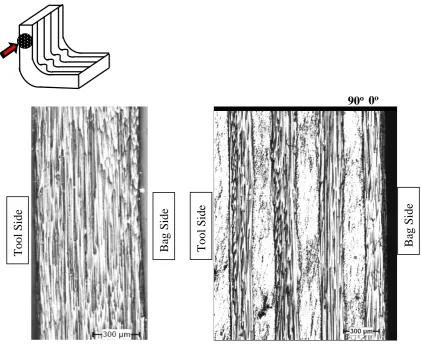
Some micrographs of the arm and corner regions were captured at for unidirectional and cross-ply parts that have a corner radius of 15 mm. In Figure 7, the micrographs of the arm regions of parts manufactured by conventional lay-up method are presented. It can be seen that all fibres extend straight and parallel for both stacking sequences at the flat arms of the parts. There is no fibre wrinkling and in-plane fibre waviness at the flat arm of the L-shaped part for unidirectional and cross-ply parts.
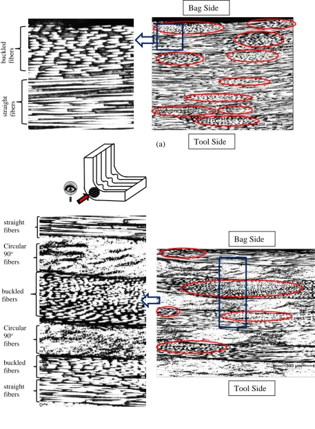
Micrographs captured from the corner side of the unidirectional and cross-ply parts laid up by conventional method are shown in Figure 8. These micrographs reveal that there is in-plane fibre waviness within the plies that extend along the circumferential direction (0o direction) for both stacking sequences. At some regions elliptical shape of buckled fibres can be seen which reveal the in-plane fibre waviness. These regions are highlighted in Figure 8.
Micrographs captured from the corner side of the unidirectional parts laid up by alternative method are shown in Figure 9. Most regions include buckled fibres of elliptical shape throughout the thickness of curved region of the part.
bridging, cure shrinkage and thermal anisotropy at the inner side of the corner regions. In-plane waviness of fibre at the corner side can be helpful for maintaining the same arc length during curing, which in turn decreases the amount of in-plane stress and causes smaller spring-in values. Second reason is the low bending stiffness due to fibre waviness at the corner side. Residual stresses occurring due to tool-part interaction cause the parts to spring-out. More fibre waviness results in less bending stiffness. Therefore, spring-out values increases due to low bending stiffness. The total amount of spring-in including all effects was reduced.
4.2 Strain and stress distribution through thickness
Strain distribution through the thickness at the curve side of the part at the end of each step of analysis is represented in Figure 12 for parts laid up by alternative method (actually the FEM developed here has only been carried out for the parts laid up by alternative method). Compressive strains occurred at the bag side of the part. These compressive strains remain at the bag side of the part at the end of analysis. This argument is supported by the observation of buckled fibres that can be seen in Figures 9.
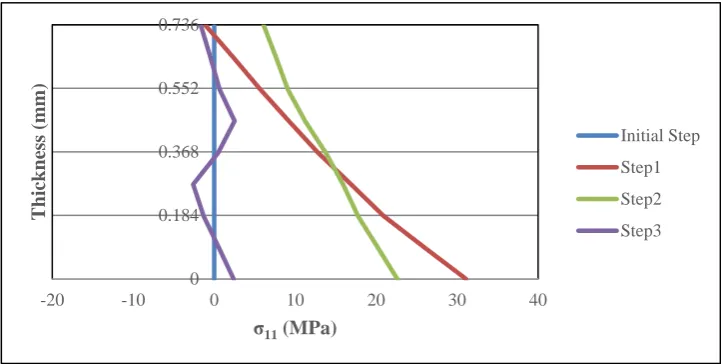
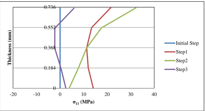
Stress distribution through thickness can be seen in Figures 13-14 for the current model. Stress values at the bag side of the part after Step 2 and Step 3 reduced with the reduction of elastic modulus of E11. Reduction ratio is the ratio of the fibre direction moduli of the non-wrinkled to non-wrinkled plies. Stress distribution for the conventional model [12], in which there is no initial step simulating ply conformation to tool, is represented in Figure 15.
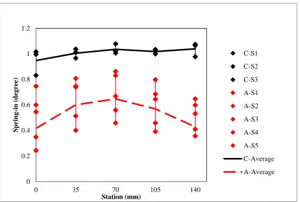
Both numerically determined and measured values of spring-in at parts produced by the conventional lay-up method are higher than the alternative lay-up method, as shown in Figures 16 and 17. In this figure, designation “C-S1” represents Sample 1 (S1) that was manufactured by conventional lay-up method and “A-S1” represents Sample 1 from another set which was manufactured by alternative lay-up method. Continuous lines in these Figures represent the results of the FEA. Reduction of the elastic modulus resulted in an increase in the spring-in values because a reduction in elastic modulus caused corresponding reductions
in stiffness and hence stress. Eventually, alternative lay-up method gave smaller spring-in
values as compared to conventional lay-up method.
∆∅= ∅[�(𝛼𝛼1 +∅− 𝛼𝛼𝛼𝛼𝑅𝑅)∆𝑇𝑇
𝑅𝑅∆𝑇𝑇 �+�
𝜀𝜀∅− 𝜀𝜀𝑅𝑅
1 +𝜀𝜀𝑅𝑅�] ( 2)
where, ∆∅ is the spring-in angle, ∅ is the initial angle of the part, 𝛼𝛼∅ is the circumferential coefficient of thermal expansion, 𝛼𝛼𝑅𝑅 is the radial coefficient of thermal expansion, 𝜀𝜀∅ is the
in-plane chemical shrinkage strain, 𝜀𝜀𝑅𝑅 is the through-the-thickness chemical strain, ∆𝑇𝑇 is the temperature change.
Effect of fibre wrinkling on cure shrinkage and coefficient of thermal expansion in the in-plane directions is not taken into account in our model, since effect of wrinkling in the current model is assumed to be only on the fibre direction modulus. The approach here in this paper is a heuristic approach to explain the effect of fibre wrinkling on spring-in using some simple assumptions and a simple model. In a more accurate model, effect of wrinkling on transverse modulus, in plane shrinkage and thermal contraction should also be taken into account.
Fibre wrinkling at the corner is beneficial in reducing the spring in, however, the trade off in mechanical properties should also be considered in order to use this lay-up method in manufacturing. Also, fibre wrinkling phenomenon is inevitable in complex-shape applications such as parts that have tighter radii so that the manufacturer should take into account the effect of fibre wrinkling on the distortion.
Conclusions
The effect of fibre waviness due to initial fibre wrinkling on spring-in was examined. Two different lay-up methods were used to manufacture L-shaped composite parts. Due to in-plane fibre waviness, buckled fibres were observed in micrographs having an elliptical shape at the corner regions of the L-shaped parts manufactured by both conventional and alternative lay-up methods but parts manufactured using the alternative lay-lay-up method includes more buckled fibres distributed through the thickness. Increasing the amount of fibre wrinkling results in lower spring-in values. Reduction in fibre direction elastic modulus E11 due to fibre buckling resulted in a decrease in spring-in values.
Acknowledgment
Nuri Ersoy and Kenan Çınar acknowledge the support of Boğaziçi University Research Fund
References
[1] Wisnom MR, Gigliotti M, Ersoy N, Campbell M and Potter KD, Mechanisms generating residual stresses and distortion during manufacture of polymer–matrix composite structures. Composites Part A 2006;37:522–529.
[2]Radford DW and Rennick T. Separating sources of manufacturing distortion in laminated composites. J Reinforced Plast Compos 2000;19(8):621–641.
[3]Fernlund G, Rahman N, Courdji R, Bresslauer M, Poursartip A, Willden K and Nelson K. Experimental and numerical study of the effect of cure cycle, tool surface, aspect ratio, and the lay-up on the dimensional stability of autoclave-processed composite parts. Composites Part A 2002;33:341–351.
[4] Albert C and Fernlund G. Spring-in and warpage of angled composite laminates. Compos. Sci. and Technol. 2002; 62: 1895–1912.
[5]Darrow DA and Jr Smith LV. Isolating components of processing induced warpage in laminated composites. J Compos Mater 2002; 36(21).
[6]White SR and Hahn HT. Process modelling of composite materials: residual stress development during cure. Part I. Model Formulation. J Compos Mater 1992;26(16):2423– 2453.
[7] Bogetti TA and Gillespie JW. Process-induced stress and deformation in thick-section thermoset composite laminates. J Compos Mater 1992; 26(5):626–659.
[8] Johnston A, Vaziri R and Poursartip A. A plane strain model for process induced deformation of laminated composite structures. J Compos Mater 2000;35(16):1435– 1469.
[9] Zhu Q, Geubelle PH, Li M and Tucker III CL. Dimensional accuracy of thermoset composites: simulation of process-induced residual stresses. J Compos Mater 2001; 35(24): 2171-2205.
[10]Arafath ARA, Vaziri R and Poursartip A. . Closed-form solution for process-induced stresses and deformation of a composite part cured on a solid tool: Part II – Curved geometries. Composites Part A 2009;40: 1545-1557.
[12]Çınar K, Öztürk UE, Ersoy N and Wisnom M. Modelling Manufacturing Deformations in Corner regions Made of Composite Materials. J Compos Mater 2014; 48 (7) : 799-813.
[13]Hubert P and Poursartip A. Aspects of the Compaction of Composite Angle Laminates: An Experimental Investigation. J Compos Mater, 2001; 35(01): 02-26.
[14]Lightfoot SC, Wisnom MR and Potter K. A New Mechanism for the Formation of Ply Wrinkles due to sheer between Plies. Composites: Part A 2013;49:139-147.
[15]Potter K, Khan B, Wisnom M, Bell T and Stevens J. Variability, Fibre Waviness and Misalignment in the Determination of the Properties of Composite Materials and Structures. Composites Part A 2008;39: 1343-1354.
[16]Bloom LD, Wang J and Potter KD. Damage Progression and Defect Sensitivity: an Experimental Study of Representative Wrinkles in Tension. Composites Part B 2013; 45(01):449-458.
[17]Gutowski GT and Tam AS. The kinematics for Forming Ideal Aligned fibre Composites into Complex Shapes. Composite Manufacturing 1990; 1(4): 219-228.
[18]Prodromou AG and Chen J. On the Relationship between Shear Angle and Wrinkling of Textile Composite Preforms. Composites Part A 1997;28: 491-503.
[19]Hancock S and Potter KD. The Use of Kinematic drape Modelling to Inform the Hand Lay-up of Complex Composite Components using Woven Reinforcement, Composites Part A 2006;37: 413-422.
[20]Potter K, Langer C, Hodgkiss B and Lamb S. Sources of Variability in Uncured Aerospace Grade Unidirectional Carbon Fibre Epoxy Preimpregnate. Composites Part A 2007;38: 905-916.
[21]Hsiao HM and Daniel IM. Effect of fibre waviness on stiffness and strength reduction of unidirectional composites under compressive loading. Composite Science and Technology 1996;56;581-593.
[22]Hsiao HM and Daniel IM. Elastic properties of composites with fibre waviness. Composites Part A 1996; 27: 931–941.
[23]Garnich MR and Karami G. Finite element for stiffness and strength of wavy fibre composites. J Compos Mater 2004;38(4): 273-292.
with periodic fibre waviness. Composite Structures 2005;67: 461-475.
[25]Karami G and Garnich M. Micromechanical study of thermoelastic behaviour of composites with periodic fibre waviness. Composites: Part B 2005:36: 241-248.
[26]Hibbit, Karlson and Sorensen Inc. ABAQUS Online Documentation 2004; Version 6.5-1.
[27]Garstka T, Ersoy N, Potter K and Wisnom MR. In situ measurements of through-the-thickness strains during processing of AS4/8552 composite. Composites Part A 2007; 38: 2517–2526.
Figure 1. a) The mould used in manufacturing: (a) dimensions in mm. (b) Schematic
representation of specimen fabrication.
Figure 2. Measurement of part geometry. The scale in (a) is in mm.
a
b
3
1 2 90o
0o
vacuum bag breather
teflon film prepreg
[image:15.595.120.514.396.575.2]a) Loading, boundary conditions and meshing for initial step
S
li
ppa
b) Loading, boundary conditions and meshing for the first (viscous) and second (rubbery) step.
[image:17.595.129.504.115.461.2]c) Loading, boundary conditions and meshing for the last (glassy) step.
.
Figure 4.a) Compressive strains occurred after initial step, b) reduction of
elastic modulus for the elements that have compressive strains.
Figure 5. Observed wrinkled fibres during lay-up
a)
b) more fibre wrinkling b)
[image:18.595.77.515.519.682.2]
Figure 6. Initial fibre wrinkles convert to in-plane fibre waviness after curing
Figure 7. Micrographs taken from the arms of the L-shaped part. The left one (a) is 4 plies
unidirectional [0]4 part and the right one (b) is 16 plies cross-ply [0/90]4s part (a) Straight fibres (0o direction) (b) Straight fibres (0o and 90o direction)
0o
90o
fibre wrinkles
in-plane fibre waviness
T
ool
S
ide
Ba
g
Si
d
e
Ba
g
Si
d
e
T
ool
S
[image:19.595.83.505.347.697.2](a)
[image:20.595.64.522.46.670.2]
(b)
Figure 8. Micrographs from the corner of the L-shaped part laid up by conventional method.
The upper one (a) is 4 plies unidirectional [0]4 part and the lower one (b) is 16 plies cross-ply [0/90]4s part
st
ra
ig
h
t
fi
b
ers
buc
kl
ed
fi
b
ers
straight fibers buckled fibers Circular 90o fibers straight fibers Circular 90o fibers
buckled fibers
Tool Side Bag Side Tool Side
Figure 9. Micrograph from the corner of the L-shaped 4 plies unidirectional [0]4 part that is
laid up by alternative method.
Figure 10. Measured spring-in for [0]4 L-section parts with R15 mm corner radius
0 0.2 0.4 0.6 0.8 1 1.2 1.4
0 35 70 105 140
[image:21.595.86.512.375.655.2]Figure 11. Measured spring-in for [0]4 L-section parts with R25 mm corner radius
Figure 12. Strain distribution through the thickness at the curve side of the part at the end of
each steps of analysis.
0 0.2 0.4 0.6 0.8 1 1.2
0 35 70 105 140
Spr ing -i n ( d eg ree) Station (mm) C-S1 C-S2 C-S3 A-S1 A-S2 A-S3 A-S4 A-S5 C-Average A-Average 0 0.184 0.368 0.552 0.736
-0.03 -0.02 -0.01 0 0.01 0.02 0.03
[image:22.595.118.479.421.601.2]Figure 13. Stress distribution through the thickness at the curve side of the part at the end of each steps of analysis in which reduction ratio is 1.
Figure 14. Stress distribution through the thickness at the curve side of the part at the end of
each steps of analysis in which reduction ratio is 2. 0
0.184 0.368 0.552 0.736
-20 -10 0 10 20 30 40
T
h
ick
n
es
s
(mm)
σ11(MPa)
Initial Step
Step1
Step2
Step3
0 0.184 0.368 0.552 0.736
-20 -10 0 10 20 30 40
T
h
ick
n
es
s
(mm)
σ11(MPa)
Initial Step
Step1
Step2
Step3
[image:23.595.117.478.338.520.2]Figure 15. Stress distribution through the thickness at the curve side of the part at the end of each steps of analysis for the conventional lay-up method.
Figure 16. Measured and predicted spring-in for [0]4 L-section parts with R15 mm corner
radius. 0 0.184 0.368 0.552 0.736
-20 -10 0 10 20 30 40
T h ick n es s (mm)
σ11(MPa)
Initial Step Step1 Step2 Step3 0 0.2 0.4 0.6 0.8 1 1.2 1.4
0 35 70 105 140
Figure 17. Measured and predicted spring-in for [0]4 L-section parts with R25 mm corner
radius.
0 0.2 0.4 0.6 0.8 1 1.2
0 35 70 105 140
Spr
ing
-i
n
(
d
eg
ree)
Station (mm)
Table 1.Material properties used in the model [12, 27].
Property Unit Initial ** Viscous** Rubbery Glassy
E11 MPa 1322 132200 132200 ** 135000
E22 = E33 MPa 165 165 165 9500
G12 = G13 MPa 22.15 44.3 44.3 4900
G23 MPa 20.8 41.6 41.6 4900
13
12 ν
ν = - 0.346 0* 0.346 0.3
23
ν - 0.982 0* 0.982 0.45
11
α µε/oC
- 0* 0* 0*
33
22 α
α = µε/oC
- 32.6 -320 32.6
cure
11
ε % - 0* 0* 0*
cure cure
33
22 ε
ε = % - 0* 0.48 0*
*Assumed to be zero. **Values were assumed.
Table 2. The applied temperature and pressure in the steps.
Temperature Pressure
Part Tool
Initial
20 oC 20 oC 0.4 MPa
Step-1
(Viscous) 165
oC 165 oC 0.7 MPa
Step-2
(Rubbery) 180
oC 180 oC 0.7 MPa
Step-3
(Glassy) 20
[image:26.595.169.428.476.619.2]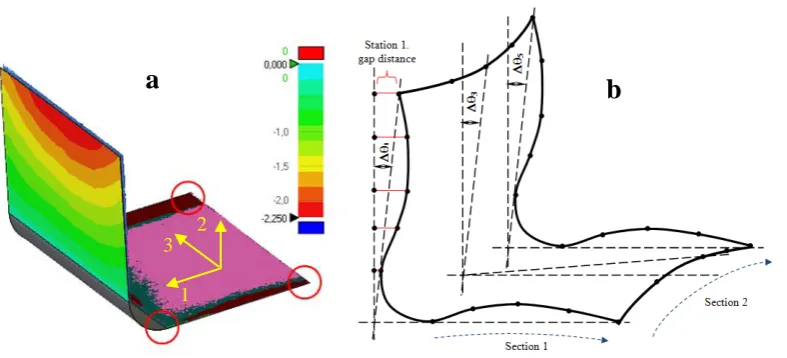


![Figure 10. Measured spring-in for [0]4 L-section parts with R15 mm corner radius](https://thumb-us.123doks.com/thumbv2/123dok_us/628002.563665/21.595.130.513.71.290/figure-measured-spring-l-section-parts-corner-radius.webp)
![Figure 17. Measured and predicted spring-in for [0]4 L-section parts with R25 mm corner](https://thumb-us.123doks.com/thumbv2/123dok_us/628002.563665/25.595.90.513.69.354/figure-measured-predicted-spring-l-section-parts-corner.webp)
